APsystems YC500i Series Installation & User Manual
Photovoltaic grid-connected inverter
Hide thumbs
Also See for YC500i Series:
- Installation & user manual (22 pages) ,
- Installation & user manual (29 pages)
Table of Contents
Troubleshooting

Related Manuals for APsystems YC500i Series


Summary of Contents for APsystems YC500i Series
- Page 1 Installation/User Manual APsystems YC500i Photovoltaic Grid-connected Inverter Version 1 7/16 APsystems 600 Ericksen Ave. NE Ste 200 Seattle, WA 98110 844-666-7035 : info@APsystems.com TEL: EMAIL www.APsystems.com WEB: © All Rights Reserved...
-
Page 2: Table Of Contents
TABLE OF CONTENTS IMPORTANT SAFETY INSTRUCTIONS Radio interference statement APsystems YC500i system introduction APsystems microinverter system installation Installation procedure APsystems microinverter system operating instructions Troubleshooting Troubleshooting a non-operating APsystems microinverter Technical data Wiring diagrams APsystems YC500i Installation/User Manual... -
Page 3: Important Safety Instructions
APsystems microinverter system and the PV – array. ✔ Be aware that the body of the APsystems microinverter is the heat sink and can reach high temperatures. To reduce risk of burns, do not touch the body of the microinverter. -
Page 4: Radio Interference Statement
Relocate the receiving antenna and keep it well away from the equipment. b) Consult the dealer or an experienced radio / TV technician for help. Changes or modifications not expressly approved by the party responsible for compliance may void the user’s authority to operate the equipment. APsystems YC500i Installation/User Manual... -
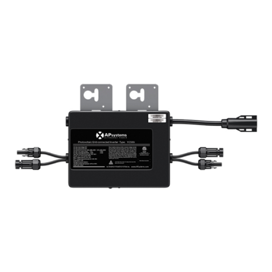
Page 5: Apsystems Yc500I System Introduction
✹ APsystems Energy Communication Unit (ECU) • APsystems Energy Communication Unit (ECU) ✹ APsystems Energy Monitor and Analysis (EMA) web-based • APsystems Energy Monitor and Analysis (EMA) web-based monitoring and analysis monitoring and analysis system system Figure 1 This integrated system improves safety;... - Page 6 More reliable than centralized or string inverters The distributed APsystems microinverter system ensures that no single point of system failure exists across the PV–array. APsystems microinverters are designed to operate at full power at ambient outdoor temperatures of up to 149°F (65°C). The inverter housing is designed for outdoor installation and complies with the NEMA 6 environmental enclosure rating.
- Page 7 The APsystems YC500 microinverters connect with the Split-phase grid, and operate with most 60 and 72 cell PV modules. For more information, please see the Technical Data page (page 16) of this manual. MODEL AC GRID PV MODULE MAX.# MODULE CONNECTOR...
-
Page 8: Apsystems Microinverter System Installation
WARNING: Before installing or using an APsystems microinverter, please read all instructions and warnings in the technical documents and on the APsystems microinverter system itself as well as on the PV array. WARNING: Be aware that installation of this equipment includes ... -
Page 9: Installation Procedure
Connect the open wire end of the AC bus cable into the junction box using an appropriate gland or strain relief fitting. Wire the conductors: L1-BLACK; L2-RED; N-WHITE; PE-GREEN Connect the AC branch circuit junction box to the point of utility interconnection. APsystems YC500i Installation/User Manual... - Page 10 Step 3 – Attach the APsystems microinverters to the Step 3 -‐‑ A ttach t he A Psystems m icroinverters t o t he r acking o r t he P V m odule f rame ...
- Page 11 Step 4 -‐ C onnect t he A Psystems m icroinverter t o A C b us c able Step 4 – Connect the APsystems microinverter to AC bus ...
- Page 12 Step 6 -‐‑ C onnect A Psystems M icroinverters t o t he P V M odules Step 6 - Connect APsystems Microinverters to the PV Modules Step ...
- Page 13 a ppendix o f t his m anual o r A Psystems w ebsite ww.APsystems.com serial number labels. Peel labels off, affix one to the respective location on the APsystems installation map, and fill in A,B in the label below (figure 11) according to the layout on the roof.
-
Page 14: Apsystems Microinverter System Operating Instructions
3. Plug in the ECU and follow the instructions according to the instructions in the ECU Installation and Operation Manual. 4. The APsystems microinverters will start to send performance data over power line to the ECU. The time required for all the microinverters in the system to report to the ECU will vary with the number of microinverters in the system. -
Page 15: Troubleshooting
AC connector of the first microinverter in a branch circuit is suitable as a means of disconnection. The APsystems microinverter is powered by the PV module DC power. WARNING: AFTER disconnecting the DC power, when reconnecting the PV modules to the ... -
Page 16: Troubleshooting A Non-Operating Apsystems Microinverter
Verify the PV module DC voltage is within the allowable range shown in the Technical Data section (page 16) of this manual. If the problem persists, call APsystems Customer Support. Do not attempt to repair the APsystems microinverter. If WARNING: troubleshooting methods fail, following the documented RMA procedures, return the ... - Page 17 Replace a microinverter Follow the procedure to replace a failed APsystems microinverter: Disconnect the APsystems microinverter from the PV Module, in the order shown below: 1. Disconnect the AC by turning off the branch circuit breaker. 2. Disconnect the PV module DC wire connectors from the microinverter.
-
Page 18: Technical Data
APsystems YC500i datasheet for Input specifications. You must match the DC operating voltage range of the WARNING: PV module with the allowable input voltage range of the APsystems Microinverter. The maximum open circuit voltage of the PV module must WARNING: not exceed the specified maximum input voltage of the APsystems. - Page 19 Specifications subject to change without notice – please ensure you are using the most recent version found at **Programmable per customer and utility requirements. All settings UL approved. APsystems.com 600 Ericksen Ave NE, Suite 200, Seattle, WA 98110 | 844.666.7035 | APsystems.com 07.19.16 © All Rights Reserved...
-
Page 20: Wiring Diagrams
D iagram YC500I S ample W iring D iagram – 1 20V/240V S plit P hase YC500i Sample Wiring Diagram – 120V/240V Split Phase Figure 12 APsystems YC500i Installation/User Manual...
Need help?
Do you have a question about the YC500i Series and is the answer not in the manual?
Questions and answers