Table of Contents
Advertisement
Installation / User Manual
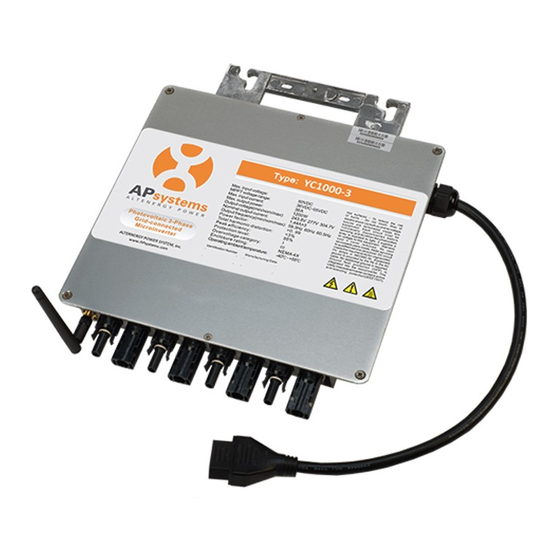
APsystems YC1000-3
Photovoltaic 3-PhaseGrid-connected Microinverter
Rev 1.3
Please scan the QR code to get
mobile app and more support
to help the installation.
ALTENERGY POWER SYSTEM Inc.
WEB: www.APsystems.com
APsystems Europe
Rue des Monts dor ZAC de Folliouses Sud-Les Echets 01700 Miribel, France
TEL: +33-481 65 60 40
EMAIL: emea@APsystems.com
(For Europe)
© All Rights Reserved
Advertisement
Table of Contents
Troubleshooting

Related Manuals for APsystems YC1000-3-3


Summary of Contents for APsystems YC1000-3-3
- Page 1 Installation / User Manual APsystems YC1000-3 Photovoltaic 3-PhaseGrid-connected Microinverter Rev 1.3 Please scan the QR code to get mobile app and more support to help the installation. ALTENERGY POWER SYSTEM Inc. WEB: www.APsystems.com APsystems Europe Rue des Monts dor ZAC de Folliouses Sud-Les Echets 01700 Miribel, France TEL: +33-481 65 60 40 EMAIL: emea@APsystems.com...
- Page 2 Step 3 - Attaching the antenna to the Microinverter, and keep the antenna vertical to the earth..10 Step 4 - Connecting the APsystems Microinverter AC Cables to the AC bus cable........10 Step 5 - Connecting APsystems Microinverters to the PV Module............11 Step 6 - Install a protective end cap at the end of AC bus cable..............11...
-
Page 3: Radio Interference Statement
APsystems Photovoltaic Grid-connected Inverter (Microinverter). To reduce the risk of electrical shock and ensure the safe installation and operation of the APsystems Microinverter, the following symbols appear throughout this document to indicate dangerous conditions and important safety instructions. -
Page 4: Safety Instructions
APsystems Microinverter system and the solar-array. Be aware that the body of the APsystems Microinverter is the heat sink and can reach a temperature of 80°C. To reduce risk of burns, do not touch the body of the Microinverter. -
Page 5: Symbols Replace Words On The Equipment, On A Display
EMC and is personnel authorized to energize, ground, and tag equipment, systems, and circuits in accordance with established safety procedures. The inverter and endues system may only be commissioned and operated by qualified personnel. APsystems YC1000-3 Installation/User Manual... -
Page 6: Apsystems Yc1000-3 System Introduction
APsystems YC1000-3 System Introduction The APsystems Microinverter is used in utility-interactive grid-tied applications, comprised of three key elements: APsystems Microinverter APsystems Energy Communication Unit (ECU) APsystems Energy Monitor and Analysis (EMA) web-based monitoring and analysis system Meter... - Page 7 Ethernet or Wi-Fi connection to a broadband router. After installing and setting the ECU (see ECU manual), the full network of APsystems Microinverters automatically reports to the APsystems Energy Monitor and analysis (EMA) web server.
-
Page 8: Apsystems Three-Phase Microinverter Yc1000-3
60, 72, 84 and 96 cell PV modules. For more information, please see the Technical Data page (p.18) of this manual, or sign in APsystems website to check online with our tool Edecider : www.emea/APsystems.com Model Max. -
Page 9: Apsystems Microinverter System Installation
Installation MUST comply with local regulations and technical rules. Special Statement! An AC GFCI device should not be used to protect the dedicated circuit to the APsystems microinverter even though it is an outside circuit. None of the small GFCI devices (5mA-30 mA) are designed for back feeding and will be damaged if back feed. -
Page 10: Installation Procedures
Installation Procedures APsystems Microinverters are designed to only operate when they can sense power coming from the grid. Even if they are plugged into the solar array, they will not turn themselves on until they can read power from the grid. -
Page 11: Step 3 - Attaching The Antenna To The Microinverter, And Keep The Antenna Vertical To The Earth
Step 3 - Attaching the antenna to the Microinverter, and keep the antenna vertical to the earth Figure 3 Step 4 - Connecting the APsystems Microinverter AC Cables to the AC bus cable Figure 4 Cover all unused T connectors with sealing caps to protect the T connectors. -
Page 12: Step 5 - Connecting Apsystems Microinverters To The Pv Module
Installation Procedures Step 5 - Connecting APsystems Microinverters to the PV Module Place the PV modules into position on the racking and connect the DC input cables to the microinverters based on optimum layout configuration (up to four PV modules per microinverter). -
Page 13: Step 7 - Installing The Ac Branch Circuit Junction Box
Step 8 - Completing the APsystems Installation Map Fill in the APsystems Warranty Cards, which provide system information and the installation map. Feel free to provide your own layout if a larger or more intricate installation map is required. The layout map provided is designed to accommodate labels in vertical or horizontal orientation to meet all the field PV connections. -
Page 14: Step 9 - Place A Warning Notice
Installation Procedures b. Fill out the warranty cards and email to APsystems at support@APsystems.com. c. Register the system using your Installer Account on the APsystems EMA. You can then use the EMA website to view detailed performance of the PV system. -
Page 15: Apsystems Microinverter System Operating Instructions
2. Turn ON the main utility-grid AC circuit breaker. Your system will start producing power after a five-minute safety delay period. 3. The APsystems Microinverters will start to send performance data over wireless to the ECU. The time required for all the microinverters in the system to report to the ECU will vary with the number of microinverters in the system. -
Page 16: Troubleshooting
Always disconnect AC power before disconnecting WARNING: the PV module wires from the APsystems microinverter. The APsystems microinverter is powered by PV module WARNING: DC power. Make sure you disconnect and reconnect the DC connections to watch for the three short LED flashes indicating start up. -
Page 17: Troubleshooting A Non-Operating Apsystems Microinverter
5. Check the DC connections between the microinverter and the PV module. 6. Verify the PV module DC voltage is within the allowable range shown 7. If the problem persists, please call APsystems Technical Support. in the Technical Data of this manual. -
Page 18: Replace A Microinverter
Follow the procedure to replace a failed APsystems Microinverter. A. Remove the APsystems microinverter from the PV Module, in the following order: 1. Disconnect the AC by turning off the branch circuit breaker. 2. Cover the module with an opaque cover. -
Page 19: Technical Data
WARNING: the PV module with the allowable input voltage range of the APsystems Microinverter. The maximum open circuit voltage of the PV module WARNING: must not exceed the specified maximum input voltage of the APsystems microinverter. APsystems YC1000-3 Installation/User Manual... -
Page 20: Mechanical Data
APsystems YC1000-3 Microinverter Datasheet Region France Switzerland Netherlands Portugal Model YC1000-3-EU Input Data (DC) MPPT Voltage Range 16V-55V Operation Voltage Range 16V-55V Maximum Input Voltage Startup Voltage Maximum Input Current 14.8A x 4 Output Data (AC) 3-Phase Grid Type 230V/400V... -
Page 21: Wiring Diagram
Wiring Diagram Sample Wiring Diagram - Three Phase Figure 12 APsystems YC1000-3 Installation/User Manual... -
Page 22: Warranty Card
The APsystems Installation Map is a diagram of the physical location of each microinverter in your PV installation. Each APsystems microinverter has a removable serial number label located on the mounting plate. Peel the label and affix it to the respective location on the APsystems installation map.
Need help?
Do you have a question about the YC1000-3-3 and is the answer not in the manual?
Questions and answers