Table of Contents
Advertisement
Quick Links
www.ti.com
User's Guide
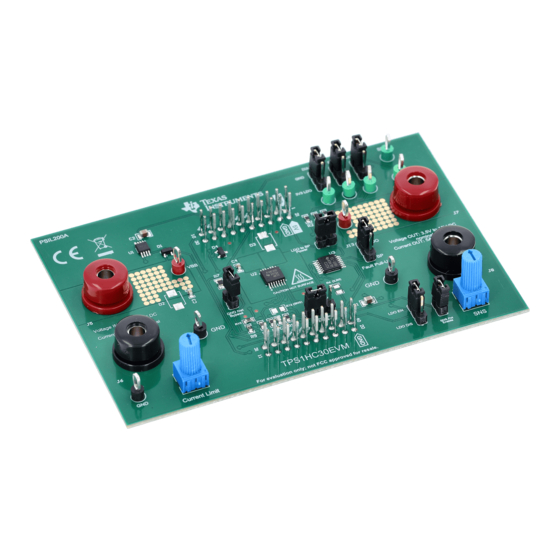
TPS1HC30-Q1 Evaluation Module
The TPS1HC30EVM is a hardware evaluation module (EVM) used to enable hardware engineers to evaluate
the full performance and functionality of the TPS1HC30-Q1 automotive high side switch. The TPS1HC30EVM
contains everything needed to test and assess the TPS1HC30-Q1 before designing it into part of a greater
application power system. The evaluation module is designed to either be used as a standalone board with an
attached voltage supply and output load or in conjunction with an underlying Texas Instruments microcontroller
by using the standardized BoosterPack
programmable current limiting, and transient suppression are enabled and visible through use of this evaluation
module.
1
Introduction.............................................................................................................................................................................2
™
Operation.......................................................................................................................................................
4 Connection Descriptions.......................................................................................................................................................
6 Transient Protection...............................................................................................................................................................
7 TPS1HC30EVM Assembly Drawings and Layout................................................................................................................
Materials.....................................................................................................................................................................14
9 Appendix - TPL0102-100 Resistance Codes......................................................................................................................
Layer...................................................................................................................................................................8
Figure 7-2. Power Layer..............................................................................................................................................................
Figure 7-3. Ground Layer..........................................................................................................................................................
Figure 7-4. Bottom Layer...........................................................................................................................................................
Figure 7-5. 3D View - Top..........................................................................................................................................................
Bottom.....................................................................................................................................................13
™
Pin Assignment...................................................................................................................................
Table 4-1. Connections and Test Points......................................................................................................................................
Configurations................................................................................................................................................5
Trademarks
™
BoosterPack
and LaunchPad
All trademarks are the property of their respective owners.
SLVUCI3 - JUNE 2022
Submit Document Feedback
ABSTRACT
™
headers. A wide range of application features such as current sensing,
Table of Contents
....................................................................................................................................................4
Configuration..................................................................................................................6
List of Figures
Schematic.......................................................................................................................................4
List of Tables
™
are trademarks of Texas Instruments.
Copyright © 2022 Texas Instruments Incorporated
Table of Contents
TPS1HC30-Q1 Evaluation Module
3
5
7
8
16
9
10
11
12
3
5
1
Advertisement
Table of Contents

Subscribe to Our Youtube Channel
Related Manuals for Texas Instruments TPS1HC30-Q1


Summary of Contents for Texas Instruments TPS1HC30-Q1
-
Page 1: Table Of Contents
TPS1HC30-Q1 automotive high side switch. The TPS1HC30EVM contains everything needed to test and assess the TPS1HC30-Q1 before designing it into part of a greater application power system. The evaluation module is designed to either be used as a standalone board with an... -
Page 2: Introduction
TPS1HC30-Q1 automotive high side switch. This evaluation board provides a seamless way to connect a power supply to the input of the TPS1HC30-Q1, connect a load to the output channel, and switch on and off the device using the control pins of the chip itself. An onboard 3.3-V LDO is included on the EVM to simplify controlling signals to the TPS1HC30-Q1 and easily assert and deassert logic signals by the use of a set of external hardware jumpers. -
Page 3: Boosterpack ™ Operation
(controlling the current limit) J2-5 EN to enable VOUT Active high. Can be connected to PWM. Controls latching behavior of the TPS1HC30-Q1. See J2-6 LATCH pin of TPS1HC30-Q1 the device data sheet for details. Enables and disables diagnostics for the TPS1HC30-... -
Page 4: Tps1Hc30Evm Schematic
TPL0102-100PWR Timer_Cap/GPIO ! SPI_MOSI GPIO ! SPI_MISO GPIO ! SPI_CS/GPIO ! GPIO ! SPI_CS/GPIO ! GPIO ! GPIO ! SSQ-110-03-T-D Figure 3-1. TPS1HC30EVM Schematic TPS1HC30-Q1 Evaluation Module SLVUCI3 – JUNE 2022 Submit Document Feedback Copyright © 2022 Texas Instruments Incorporated... -
Page 5: Connection Descriptions
Enable line for the TPS1HC30-Q1 LATCH Controls latch functionality for the TPS1HC30-Q1 Current sense test point for the current sense output of the TPS1HC30-Q1 Open-drain fault test point for the TPS1HC30-Q1. Pullup source can FAULT be configured using J13. Table 4-2. Jumper Configurations Jumper Function, Setting POT enables the physical "Current Limit"... -
Page 6: Current Limit And Current Sense Configuration
SNS pin. If this jumper is not populated, the solder down pad, R13, must be used to provide the necessary resistance value. The output of the TPS1HC30-Q1's SNS pin is an analog current that is a representation of the load current going through the switch. -
Page 7: Transient Protection
ESD, surges, and inductive load turn-offs. These protection mechanisms are provided in addition to the integrated transient mitigation features of the TPS1HC30-Q1. Refer to the TPS1HC30-Q1 data sheet for more information about the internal protections that the device provides. -
Page 8: Tps1Hc30Evm Assembly Drawings And Layout
TPS1HC30EVM Assembly Drawings and Layout www.ti.com 7 TPS1HC30EVM Assembly Drawings and Layout Figure 7-1. Top Layer TPS1HC30-Q1 Evaluation Module SLVUCI3 – JUNE 2022 Submit Document Feedback Copyright © 2022 Texas Instruments Incorporated... -
Page 9: Figure 7-2. Power Layer
TPS1HC30EVM Assembly Drawings and Layout Figure 7-2. Power Layer SLVUCI3 – JUNE 2022 TPS1HC30-Q1 Evaluation Module Submit Document Feedback Copyright © 2022 Texas Instruments Incorporated... -
Page 10: Figure 7-3. Ground Layer
TPS1HC30EVM Assembly Drawings and Layout www.ti.com Figure 7-3. Ground Layer TPS1HC30-Q1 Evaluation Module SLVUCI3 – JUNE 2022 Submit Document Feedback Copyright © 2022 Texas Instruments Incorporated... -
Page 11: Figure 7-4. Bottom Layer
TPS1HC30EVM Assembly Drawings and Layout Figure 7-4. Bottom Layer SLVUCI3 – JUNE 2022 TPS1HC30-Q1 Evaluation Module Submit Document Feedback Copyright © 2022 Texas Instruments Incorporated... -
Page 12: Figure 7-5. 3D View - Top
TPS1HC30EVM Assembly Drawings and Layout www.ti.com Figure 7-5. 3D View - Top TPS1HC30-Q1 Evaluation Module SLVUCI3 – JUNE 2022 Submit Document Feedback Copyright © 2022 Texas Instruments Incorporated... -
Page 13: Figure 7-6. 3D View - Bottom
TPS1HC30EVM Assembly Drawings and Layout Figure 7-6. 3D View - Bottom SLVUCI3 – JUNE 2022 TPS1HC30-Q1 Evaluation Module Submit Document Feedback Copyright © 2022 Texas Instruments Incorporated... -
Page 14: Bill Of Materials
J4, SH-J5, SH-J6, SH-J7, Shunt, 100mil, Gold plated, Black Shunt SNT-100-BK-G Samtec SH-J8, SH-J9 Red Multipurpose TP1, TP2 Test Point, Multipurpose, Red, TH 5010 Keystone Testpoint TPS1HC30-Q1 Evaluation Module SLVUCI3 – JUNE 2022 Submit Document Feedback Copyright © 2022 Texas Instruments Incorporated... - Page 15 RES, 59.0 k, 1%, 0.125 W, AEC-Q200 Grade 0, 0805 805 ERJ-6ENF5902V Panasonic 1.00 k RES, 1.00 k, 1%, 0.25 W, 0805 ERJ-P06F1001V Panasonic SLVUCI3 – JUNE 2022 TPS1HC30-Q1 Evaluation Module Submit Document Feedback Copyright © 2022 Texas Instruments Incorporated...
-
Page 16: Appendix - Tpl0102-100 Resistance Codes
0x28h 0010 1000 84.38 0x29h 0010 1001 83.98 0x2Ah 0010 1010 83.59 0x2Bh 0010 1011 83.20 0x2Ch 0010 1100 82.81 0x2Dh 0010 1101 82.42 TPS1HC30-Q1 Evaluation Module SLVUCI3 – JUNE 2022 Submit Document Feedback Copyright © 2022 Texas Instruments Incorporated... - Page 17 0x58h 0101 1000 65.63 0x59h 0101 1001 65.23 0x5Ah 0101 1010 64.84 0x5Bh 0101 1011 64.45 0x5Ch 0101 1100 64.06 0x5Dh 0101 1101 63.67 SLVUCI3 – JUNE 2022 TPS1HC30-Q1 Evaluation Module Submit Document Feedback Copyright © 2022 Texas Instruments Incorporated...
- Page 18 0x88h 1000 1000 46.88 0x89h 1000 1001 46.48 0x8Ah 1000 1010 46.09 0x8Bh 1000 1011 45.70 0x8Ch 1000 1100 45.31 0x8Dh 1000 1101 44.92 TPS1HC30-Q1 Evaluation Module SLVUCI3 – JUNE 2022 Submit Document Feedback Copyright © 2022 Texas Instruments Incorporated...
- Page 19 0xB8h 1011 1000 28.13 0xB9h 1011 1001 27.73 0xBAh 1011 1010 27.34 0xBBh 1011 1011 26.95 0xBCh 1011 1100 26.56 0xBDh 1011 1101 26.17 SLVUCI3 – JUNE 2022 TPS1HC30-Q1 Evaluation Module Submit Document Feedback Copyright © 2022 Texas Instruments Incorporated...
- Page 20 0xE8h 1110 1000 9.38 0xE9h 1110 1001 8.98 0xEAh 1110 1010 8.59 0xEBh 1110 1011 8.20 0xECh 1110 1100 7.81 0xEDh 1110 1101 7.42 TPS1HC30-Q1 Evaluation Module SLVUCI3 – JUNE 2022 Submit Document Feedback Copyright © 2022 Texas Instruments Incorporated...
- Page 21 1111 1010 2.34 0xFBh 1111 1011 1.95 0xFCh 1111 1100 1.56 0xFDh 1111 1101 1.17 0xFEh 1111 1110 0.78 255 (full-scale) 0xFFh 1111 1111 SLVUCI3 – JUNE 2022 TPS1HC30-Q1 Evaluation Module Submit Document Feedback Copyright © 2022 Texas Instruments Incorporated...
- Page 22 STANDARD TERMS FOR EVALUATION MODULES Delivery: TI delivers TI evaluation boards, kits, or modules, including any accompanying demonstration software, components, and/or documentation which may be provided together or separately (collectively, an “EVM” or “EVMs”) to the User (“User”) in accordance with the terms set forth herein.
- Page 23 www.ti.com Regulatory Notices: 3.1 United States 3.1.1 Notice applicable to EVMs not FCC-Approved: FCC NOTICE: This kit is designed to allow product developers to evaluate electronic components, circuitry, or software associated with the kit to determine whether to incorporate such items in a finished product and software developers to write software applications for use with the end product.
- Page 24 www.ti.com Concernant les EVMs avec antennes détachables Conformément à la réglementation d'Industrie Canada, le présent émetteur radio peut fonctionner avec une antenne d'un type et d'un gain maximal (ou inférieur) approuvé pour l'émetteur par Industrie Canada. Dans le but de réduire les risques de brouillage radioélectrique à...
- Page 25 www.ti.com EVM Use Restrictions and Warnings: 4.1 EVMS ARE NOT FOR USE IN FUNCTIONAL SAFETY AND/OR SAFETY CRITICAL EVALUATIONS, INCLUDING BUT NOT LIMITED TO EVALUATIONS OF LIFE SUPPORT APPLICATIONS. 4.2 User must read and apply the user guide and other available documentation provided by TI regarding the EVM prior to handling or using the EVM, including without limitation any warning or restriction notices.
- Page 26 Notwithstanding the foregoing, any judgment may be enforced in any United States or foreign court, and TI may seek injunctive relief in any United States or foreign court. Mailing Address: Texas Instruments, Post Office Box 655303, Dallas, Texas 75265 Copyright © 2019, Texas Instruments Incorporated...
- Page 27 TI products. TI’s provision of these resources does not expand or otherwise alter TI’s applicable warranties or warranty disclaimers for TI products. TI objects to and rejects any additional or different terms you may have proposed. IMPORTANT NOTICE Mailing Address: Texas Instruments, Post Office Box 655303, Dallas, Texas 75265 Copyright © 2022, Texas Instruments Incorporated...
Need help?
Do you have a question about the TPS1HC30-Q1 and is the answer not in the manual?
Questions and answers