Table of Contents
Advertisement
Quick Links
www.ti.com
User's Guide
TPS1HC100 Evaluation Module
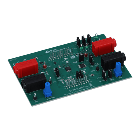
The TPS1HC100EVM is a hardware evaluation module (EVM) used to enable hardware engineers to
evaluate the full performance and functionality of the TPS1HC100B-Q1 automotive high side switch. The
TPS1HC100EVM contains everything needed to test and assess the TPS1HC100B-Q1 before designing it
into part of a greater application's power system. The evaluation module is designed to either be used as
a standalone board with an attached voltage supply and output load or in conjunction with an underlying
Texas Instruments microcontroller by using the standardized BoosterPack headers. A wide range of application
features such as current sensing, programmable current limiting, and transient suppression are enabled and
visible through use of this evaluation module.
1
Introduction.............................................................................................................................................................................2
Operation..........................................................................................................................................................3
4 Connection Descriptions.......................................................................................................................................................
6 Transient Protection...............................................................................................................................................................
7 TPS1HC100EVM Assembly Drawings and Layout..............................................................................................................
Materials.....................................................................................................................................................................13
9 Appendix - TPL0102-100 Resistance Codes......................................................................................................................
Layer...................................................................................................................................................................8
Figure 7-2. Power Layer..............................................................................................................................................................
Figure 7-3. Ground Layer..........................................................................................................................................................
Figure 7-4. Bottom Layer...........................................................................................................................................................
Figure 7-5. 3D View...................................................................................................................................................................
Table 2-1. ....................................................................................................................................................................................
Table 4-1. Connections and Test Points......................................................................................................................................
Configurations................................................................................................................................................5
Trademarks
All trademarks are the property of their respective owners.
SLVUC30 - JULY 2021
Submit Document Feedback
ABSTRACT
Table of Contents
..................................................................................................................................................4
Configuration..................................................................................................................6
List of Figures
Schematic.....................................................................................................................................4
List of Tables
Copyright © 2021 Texas Instruments Incorporated
Table of Contents
TPS1HC100 Evaluation Module
5
7
8
16
9
10
11
12
3
5
1
Advertisement
Table of Contents

Related Manuals for Texas Instruments TPS1HC100


Summary of Contents for Texas Instruments TPS1HC100
-
Page 1: Table Of Contents
Texas Instruments microcontroller by using the standardized BoosterPack headers. A wide range of application features such as current sensing, programmable current limiting, and transient suppression are enabled and visible through use of this evaluation module. -
Page 2: Introduction
Additionally, this EVM includes BoosterPack headers allowing the user to easily connect the TPS1HC100-Q1 high side switch to an underlying microcontroller and write software to control and configure the device. -
Page 3: Boosterpack Operation
TPS1HC100B-Q1. See the device data sheet for details. Enables and disables diagnostics for the J2-7 DIAG_EN pin of TPS1HC100B-Q1 TPS1HC100B-Q1. See the device data sheet for details. SLVUC30 – JULY 2021 TPS1HC100 Evaluation Module Submit Document Feedback Copyright © 2021 Texas Instruments Incorporated... -
Page 4: Tps1Hc100Evm Schematic
TPS1HC100EVM Schematic www.ti.com 3 TPS1HC100EVM Schematic Figure 3-1. TPS1HC100EVM Schematic TPS1HC100 Evaluation Module SLVUC30 – JULY 2021 Submit Document Feedback Copyright © 2021 Texas Instruments Incorporated... -
Page 5: Connection Descriptions
Connects the TPS1HC100B-Q1's LATCH signal to either the LDO's LATCH 3.3-V signal or ground Bypasses the resistor and diode ground network and connects IC GND Net Bypass ground to system ground SLVUC30 – JULY 2021 TPS1HC100 Evaluation Module Submit Document Feedback Copyright © 2021 Texas Instruments Incorporated... -
Page 6: Current Limit And Current Sense Configuration
5 Current Limit and Current Sense Configuration The current limit resistor connected to the ILIM pin configures the current limit of the TPS1HC100-Q1 device. Based off the limit of this resistor the allowed current that passes through the high side switch can be controlled. -
Page 7: Transient Protection
Optional external inductive load turnoff diode footprints on D3 to provide a mechanism to discharge an inductive load if the internal clamp is not adequate (not populated) SLVUC30 – JULY 2021 TPS1HC100 Evaluation Module Submit Document Feedback Copyright © 2021 Texas Instruments Incorporated... -
Page 8: Tps1Hc100Evm Assembly Drawings And Layout
TPS1HC100EVM Assembly Drawings and Layout www.ti.com 7 TPS1HC100EVM Assembly Drawings and Layout Figure 7-1. Top Layer TPS1HC100 Evaluation Module SLVUC30 – JULY 2021 Submit Document Feedback Copyright © 2021 Texas Instruments Incorporated... -
Page 9: Figure 7-2. Power Layer
TPS1HC100EVM Assembly Drawings and Layout Figure 7-2. Power Layer SLVUC30 – JULY 2021 TPS1HC100 Evaluation Module Submit Document Feedback Copyright © 2021 Texas Instruments Incorporated... -
Page 10: Figure 7-3. Ground Layer
TPS1HC100EVM Assembly Drawings and Layout www.ti.com Figure 7-3. Ground Layer TPS1HC100 Evaluation Module SLVUC30 – JULY 2021 Submit Document Feedback Copyright © 2021 Texas Instruments Incorporated... -
Page 11: Figure 7-4. Bottom Layer
TPS1HC100EVM Assembly Drawings and Layout Figure 7-4. Bottom Layer SLVUC30 – JULY 2021 TPS1HC100 Evaluation Module Submit Document Feedback Copyright © 2021 Texas Instruments Incorporated... -
Page 12: Figure 7-5. 3D View
TPS1HC100EVM Assembly Drawings and Layout www.ti.com Figure 7-5. 3D View TPS1HC100 Evaluation Module SLVUC30 – JULY 2021 Submit Document Feedback Copyright © 2021 Texas Instruments Incorporated... -
Page 13: Bill Of Materials
AEC-Q200 Grade 0, 0603 100kΩ Res Cermet Trimmer PTH_TRIMMER_6MM60 3362P-1-104TLF Bourns 100K Ohm 10% 1/2W _6MM99 1(Elec)/1(Mech)Turn 5mm (6.71 X 7.04 X 14.63mm) Pin Thru-Hole Tube SLVUC30 – JULY 2021 TPS1HC100 Evaluation Module Submit Document Feedback Copyright © 2021 Texas Instruments Incorporated... - Page 14 Texas Instruments Digital Potentiometer With I2C Interface and Nonvolatile Memory, PW0014A (TSSOP-14) D2, D3 Diode TVS Single Bi-Dir DO-214AA SMBJ36CA Littelfuse 36V 600W 2-Pin SMB TPS1HC100 Evaluation Module SLVUC30 – JULY 2021 Submit Document Feedback Copyright © 2021 Texas Instruments Incorporated...
- Page 15 RES, 59.0 k, 1%, 0.125 0805 ERJ-6ENF5902V Panasonic W, AEC-Q200 Grade 0, 0805 1.00k RES, 1.00 k, 1%, 0.25 W, 0805 ERJ-P06F1001V Panasonic 0805 SLVUC30 – JULY 2021 TPS1HC100 Evaluation Module Submit Document Feedback Copyright © 2021 Texas Instruments Incorporated...
-
Page 16: Appendix - Tpl0102-100 Resistance Codes
0x28h 0010 1000 84.38 0x29h 0010 1001 83.98 0x2Ah 0010 1010 83.59 0x2Bh 0010 1011 83.20 0x2Ch 0010 1100 82.81 0x2Dh 0010 1101 82.42 TPS1HC100 Evaluation Module SLVUC30 – JULY 2021 Submit Document Feedback Copyright © 2021 Texas Instruments Incorporated... - Page 17 0x58h 0101 1000 65.63 0x59h 0101 1001 65.23 0x5Ah 0101 1010 64.84 0x5Bh 0101 1011 64.45 0x5Ch 0101 1100 64.06 0x5Dh 0101 1101 63.67 SLVUC30 – JULY 2021 TPS1HC100 Evaluation Module Submit Document Feedback Copyright © 2021 Texas Instruments Incorporated...
- Page 18 0x88h 1000 1000 46.88 0x89h 1000 1001 46.48 0x8Ah 1000 1010 46.09 0x8Bh 1000 1011 45.70 0x8Ch 1000 1100 45.31 0x8Dh 1000 1101 44.92 TPS1HC100 Evaluation Module SLVUC30 – JULY 2021 Submit Document Feedback Copyright © 2021 Texas Instruments Incorporated...
- Page 19 0xB8h 1011 1000 28.13 0xB9h 1011 1001 27.73 0xBAh 1011 1010 27.34 0xBBh 1011 1011 26.95 0xBCh 1011 1100 26.56 0xBDh 1011 1101 26.17 SLVUC30 – JULY 2021 TPS1HC100 Evaluation Module Submit Document Feedback Copyright © 2021 Texas Instruments Incorporated...
- Page 20 0xE8h 1110 1000 9.38 0xE9h 1110 1001 8.98 0xEAh 1110 1010 8.59 0xEBh 1110 1011 8.20 0xECh 1110 1100 7.81 0xEDh 1110 1101 7.42 TPS1HC100 Evaluation Module SLVUC30 – JULY 2021 Submit Document Feedback Copyright © 2021 Texas Instruments Incorporated...
- Page 21 1111 1010 2.34 0xFBh 1111 1011 1.95 0xFCh 1111 1100 1.56 0xFDh 1111 1101 1.17 0xFEh 1111 1110 0.78 255 (full-scale) 0xFFh 1111 1111 SLVUC30 – JULY 2021 TPS1HC100 Evaluation Module Submit Document Feedback Copyright © 2021 Texas Instruments Incorporated...
- Page 22 STANDARD TERMS FOR EVALUATION MODULES Delivery: TI delivers TI evaluation boards, kits, or modules, including any accompanying demonstration software, components, and/or documentation which may be provided together or separately (collectively, an “EVM” or “EVMs”) to the User (“User”) in accordance with the terms set forth herein.
- Page 23 www.ti.com Regulatory Notices: 3.1 United States 3.1.1 Notice applicable to EVMs not FCC-Approved: FCC NOTICE: This kit is designed to allow product developers to evaluate electronic components, circuitry, or software associated with the kit to determine whether to incorporate such items in a finished product and software developers to write software applications for use with the end product.
- Page 24 www.ti.com Concernant les EVMs avec antennes détachables Conformément à la réglementation d'Industrie Canada, le présent émetteur radio peut fonctionner avec une antenne d'un type et d'un gain maximal (ou inférieur) approuvé pour l'émetteur par Industrie Canada. Dans le but de réduire les risques de brouillage radioélectrique à...
- Page 25 www.ti.com EVM Use Restrictions and Warnings: 4.1 EVMS ARE NOT FOR USE IN FUNCTIONAL SAFETY AND/OR SAFETY CRITICAL EVALUATIONS, INCLUDING BUT NOT LIMITED TO EVALUATIONS OF LIFE SUPPORT APPLICATIONS. 4.2 User must read and apply the user guide and other available documentation provided by TI regarding the EVM prior to handling or using the EVM, including without limitation any warning or restriction notices.
- Page 26 Notwithstanding the foregoing, any judgment may be enforced in any United States or foreign court, and TI may seek injunctive relief in any United States or foreign court. Mailing Address: Texas Instruments, Post Office Box 655303, Dallas, Texas 75265 Copyright © 2019, Texas Instruments Incorporated...
- Page 27 TI products. TI’s provision of these resources does not expand or otherwise alter TI’s applicable warranties or warranty disclaimers for TI products.IMPORTANT NOTICE Mailing Address: Texas Instruments, Post Office Box 655303, Dallas, Texas 75265 Copyright © 2021, Texas Instruments Incorporated...
Need help?
Do you have a question about the TPS1HC100 and is the answer not in the manual?
Questions and answers