Table of Contents
Advertisement
Quick Links
Advertisement
Table of Contents

Related Manuals for Metrohm Eco Titrator


Summary of Contents for Metrohm Eco Titrator
- Page 1 Eco Titrator Product manual 8.1008.8001EN / 2021-08-27...
- Page 3 Metrohm AG Ionenstrasse CH-9100 Herisau Switzerland +41 71 353 85 85 info@metrohm.com www.metrohm.com Eco Titrator Firmware version 57.1008.0011 or higher Product manual 8.1008.8001EN / 2021-08-27...
- Page 4 Disclaimer Deficiencies arising from circumstances that are not the responsibility of Metrohm, such as improper storage or improper use, etc., are expressly excluded from the warranty. Unauthorized modifications to the product (e.g. conversions or attachments) exclude any liability on the part of the manufacturer for resulting damage and its consequences.
-
Page 5: Table Of Contents
Meaning of warning signs ........... 9 3 Functional description System overview ..............11 3.1.1 Signals ................... 11 3.1.2 Interfaces and connectors ............11 Eco Titrator – Overview ............. 13 3.2.1 Dosing unit ................17 3.2.2 Bottle unit ................20 Function ................20 3.3.1 Magnetic stirrer .............. - Page 6 Table of contents ■■■■■■■■■■■■■■■■■■■■■■ 4 Delivery and packaging Delivery ................30 Packaging ................30 5 Installation Setup location ..............31 Preparing the assembly ............31 Switching the instrument on and off ........ 33 Initial assembly of the cylinder unit ........34 Mounting the support rod ..........
- Page 7 ■■■■■■■■■■■■■■■■■■■■■■ Table of contents 7.7.6 System – File management ............ 88 7.7.7 Instrument diagnosis ............. 92 7.7.8 Ethernet settings ..............93 7.7.9 Service – Brief description ............93 7.7.10 Changing the password ............93 7.7.11 COM port settings ..............94 Carrying out a pH calibration ..........
-
Page 9: Overview
■■■■■■■■■■■■■■■■■■■■■■ Overview 1 Overview Product description The Eco Titrator is a titrator for volumetric titrations for universal use that is equipped with the following functional units: Built-in magnetic stirrer ■ Dosing unit with exchangeable cylinder unit ■ Methods can be created and saved on the instrument. The methods can be exported to and imported from a connected USB flash drive. -
Page 10: Product Versions
(see example): Figure 1 Type plate (example) (01) = External article number (21) = Serial number (240) = Metrohm article number NOTICE Information on the accessories for the respective product version can be obtained either on the Internet at http://www.metrohm.com from your regional Metrohm representative. -
Page 11: Symbols And Conventions
■ https://guide.metrohm.com Accessories Up-to-date information on the scope of delivery and on optional accesso- ries can be found on the Metrohm website. Download this information as follows: Downloading the accessories list 1 Go to https://www.metrohm.com. 2 Enter the article number of the product (e.g. 2.1001.0010) into the search field. - Page 12 Accessories ■■■■■■■■■■■■■■■■■■■■■■ The PDF file with the accessories data is loaded. NOTICE Metrohm recommends downloading the accessories list from the Internet and keeping it for reference purposes. ■■■■■■■■...
-
Page 13: Safety
Safety 2 Safety Intended use Metrohm products are used for the analysis and handling of chemicals. Usage therefore requires the user to have basic knowledge and experience in handling chemicals. Knowledge regarding the application of fire preven- tion measures prescribed for laboratories is also mandatory. -
Page 14: Requirements For Operating Personnel
Always have maintenance work and repairs on electrical components ■ carried out by a regional Metrohm service representative. Disconnect the product from the energy supply immediately if at least ■ one of the following cases occurs: –... -
Page 15: Danger From Highly Flammable Substances
Dispose of chemically contaminated materials (e.g. cleaning material) in ■ accordance with regulations. Proceed as follows in case of a return shipment to Metrohm AG or a ■ regional Metrohm representative: – Decontaminate the product or product component. -
Page 16: Danger During Transport Of The Product
Design of warning messages ■■■■■■■■■■■■■■■■■■■■■■ 2.4.5 Danger during transport of the product Chemical or biological substances may be spilled during the transport of the product. Parts of the product may fall down or may be damaged. There is a risk of injury from chemical or biological substances and pieces of broken glass. -
Page 17: Meaning Of Warning Signs
■■■■■■■■■■■■■■■■■■■■■■ Safety WARNING Type or source of danger Consequences when not observing the notice: A serious injury that may result in death is probable. Measures to avoid the danger ■ CAUTION Type or source of danger Consequences when not observing the notice: A minor to moderate injury is probable. - Page 18 Meaning of warning signs ■■■■■■■■■■■■■■■■■■■■■■ Warning sign Meaning Warning of flammable materials Warning of corrosive substances Warning of optical radiation Warning of laser beams Depending on the intended use of the product, the corresponding warn- ing sign stickers must be placed on the product. ■■■■■■■■...
-
Page 19: Functional Description
■■■■■■■■■■■■■■■■■■■■■■ Functional description 3 Functional description System overview 3.1.1 Signals The status display uses flashing patterns to display the operating status of the instrument. Table 3 Status display Signal Flashing pat- Meaning tern LED lights up Ready for operation green LED flashes In operation / Waiting green (slowly) - Page 20 System overview ■■■■■■■■■■■■■■■■■■■■■■ Designation Type Ethernet RJ-45 Connector for RS-232 instrument server Remote D-Sub Connector for devices with remote interface Power OUT Mini DIN Power IN Mini DIN Connector for the energy supply Socket F High-ohm measuring input for pH electrodes and redox electrodes Socket B, 4 mm High-ohm measuring input for...
-
Page 21: Eco Titrator - Overview
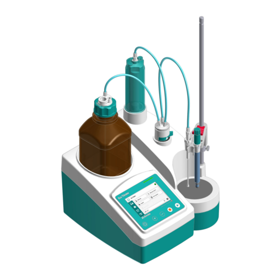
■■■■■■■■■■■■■■■■■■■■■■ Functional description Eco Titrator – Overview Figure 2 Eco Titrator – Front Bottle holder Space for cylinder unit Flat stopcock Stand attachment Magnetic stirrer Status display, touch screen and con- trol bar ■■■■■■■■... - Page 22 Eco Titrator – Overview ■■■■■■■■■■■■■■■■■■■■■■ Figure 3 Eco Titrator – Rear Type plate USB connector (USB 1 and USB 2) Ethernet connector (RJ-45) Remote connector "Power OUT" connector "Power IN" connector Pol connector Temp connectors 10 Ind connector Ref connector...
- Page 23 ■■■■■■■■■■■■■■■■■■■■■■ Functional description Figure 4 Eco Titrator – Accessories Cylinder unit Tubing connections Electrode cable Electrode Electrode holder Guide sleeve Clamping ring Support rod Buret tip 10 Amber glass bottle with GL 45 thread 11 Clip for SGJ 14/15 12 Bottle cap...
- Page 24 Eco Titrator – Overview ■■■■■■■■■■■■■■■■■■■■■■ Figure 5 Eco Titrator – Peripherals Printer Q3X (opt. accessory) USB flash drive Ethernet cable (opt. accessory) Power supply unit ■■■■■■■■...
-
Page 25: Dosing Unit
■■■■■■■■■■■■■■■■■■■■■■ Functional description 3.2.1 Dosing unit Figure 6 Dosing unit – Overview Cylinder unit Push rod (dosing drive) Flat stopcock ■■■■■■■■... - Page 26 Eco Titrator – Overview ■■■■■■■■■■■■■■■■■■■■■■ 3.2.1.1 Cylinder unit Figure 7 Cylinder unit – Overview Light protection Dosing cylinder Piston with sealing lips and piston rod Mounting ring ■■■■■■■■...
- Page 27 ■■■■■■■■■■■■■■■■■■■■■■ Functional description 3.2.1.2 Flat stopcock Figure 8 Flat stopcock – Overview Connector for the tubing connection to Connector for the tubing connection to the bottle the cylinder unit Connector for the tubing connection to Switching lever the buret tip ■■■■■■■■...
-
Page 28: Bottle Unit
Function ■■■■■■■■■■■■■■■■■■■■■■ 3.2.2 Bottle unit Figure 9 Bottle unit – Overview Cannula Threaded stopper Bottle cap Amber glass bottle with GL 45 thread Clip for SGJ 14/15 Adsorber tube Function 3.3.1 Magnetic stirrer The magnetic stirrer ensures that the sample is well mixed. The stirring rate can be adjusted depending on the amount and viscosity of the sam- ple. -
Page 29: Indicators And Controls
■■■■■■■■■■■■■■■■■■■■■■ Functional description cylinder of the cylinder unit and is responsible for accurate dosing of the solution. The flat stopcock switches between filling and emptying the dosing cylin- der of the cylinder unit. Once the cylinder unit is put into place, the dosing drive and the flat stop- cock handle the following functions: Raising and lowering the piston: ■... -
Page 30: Interfaces And Connectors
Interfaces and connectors ■■■■■■■■■■■■■■■■■■■■■■ Interfaces and connectors Figure 12 Eco Titrator – Interfaces and connectors Ethernet Connect USB flash drive, printer, balance, Remote control via local network etc. Remote Power IN Connect analog remote control / Eco Dosi- Connect power supply unit... -
Page 31: Remote Interface
Pin assignment of the remote interface Figure 13 Pin assignment of remote socket and remote plug The above figure of the pin assignment applies to all Metrohm instru- ments with 9-pin D-Sub remote connector. Table 6 Inputs and outputs of the remote interface Pin no. - Page 32 Remote interface ■■■■■■■■■■■■■■■■■■■■■■ Open Collector > 200 ms active = low, inactive = high = 20 mA, V = 40 V +5 V: maximum load = 20 mA Status diagrams of the remote interface EOD = End of Determination Titration modes MET, DET, SET Ready/EOD OUTPUT 0 Activ./Dos.
-
Page 33: Remote Control
■■■■■■■■■■■■■■■■■■■■■■ Functional description Ready/EOD OUTPUT 0 Activ./Dos. OUTPUT 1 Titr./Determ. OUTPUT 2 Cond. OK OUTPUT 3 Error OUTPUT 4 Start INPUT 0 Stop INPUT 1 Figure 16 Remote status diagram CAL, without error event Ready/EOD OUTPUT 0 Activ./Dos. OUTPUT 1 Titr./Determ. - Page 34 Remote control ■■■■■■■■■■■■■■■■■■■■■■ Command Function Comment Corresponds to the [START] Start/Continue or [Continue] key. Corresponds to the [STOP] Stop key. Hold Hold the method run. Scan instrument Acknowledgements: Ready;0, status Busy;0 or Hold;0 (0 = no mes- sage). If a message on the instrument requires the interaction of the user, the acknowledgement of the status scan displays the...
-
Page 35: Arithmetic Algorithms
■■■■■■■■■■■■■■■■■■■■■■ Functional description Command Function Comment $Q(variable) Request varia- Examples for variables: EP1, ble value R1, C00. Complete list of the variables: see chapter Formula editor. The values of the variables are only available after the end of a determina- tion (in the status 'ready'). - Page 36 Arithmetic algorithms ■■■■■■■■■■■■■■■■■■■■■■ rounded up. Negative digits will be rounded in accordance with their amount, i.e. away from zero. Examples: 2.33 yields 2.3 2.35 yields 2.4 2.47 yields 2.5 –2.38 yields –2.4 –2.45 yields –2.5 Statistics The arithmetic mean value and the absolute and relative standard devia- tions of results are calculated: You can statistically evaluate a maximum of five results (1 ≤...
- Page 37 ■■■■■■■■■■■■■■■■■■■■■■ Functional description If the same result is expressed in "g/L" (1.23456789158763 g/L), and is also rounded off to three decimal places, this yields 1.235 g/L. ■ I.e. you obtain the lowest losses in accuracy with rounding when you select the application and the numerical format in such a way that the numbers displayed have as many places before the decimal point as possi- ble.
-
Page 38: Delivery And Packaging
Delivery ■■■■■■■■■■■■■■■■■■■■■■ 4 Delivery and packaging Delivery Inspect the delivery immediately upon receipt: Check the delivery against the delivery note to ensure completeness. ■ Check the product for damage. ■ If the delivery is incomplete or damaged, contact your regional Met- ■... -
Page 39: Installation
■ sockets) against moisture. If you suspect that moisture has gotten into the product, discon- ■ nect the product from the energy supply. Then notify Metrohm Service. Only personnel who have been issued Metrohm qualification may ■ perform service and repair work on electrical and electronic com- ponents. - Page 40 Preparing the assembly ■■■■■■■■■■■■■■■■■■■■■■ Connecting the power cord Figure 18 Rear of the instrument – Connecting the power cord NOTICE The flat side of the plug of the power supply unit must face downwards. Connect the power supply unit to the Power IN connector. Note the orientation (see figure).
-
Page 41: Switching The Instrument On And Off
■■■■■■■■■■■■■■■■■■■■■■ Installation Switching the instrument on and off Switching on the instrument Prerequisite The power cord is connected. 1 Press the key. The instrument is initialized and a system test is performed. If the Beep parameter is activated in the system settings of the parameters, then a beep will be heard after switch-on. -
Page 42: Initial Assembly Of The Cylinder Unit
Initial assembly of the cylinder unit ■■■■■■■■■■■■■■■■■■■■■■ Initial assembly of the cylinder unit The initial assembly of the cylinder unit is carried out with an installation wizard. The installation wizard not only supports the assembly of the cylinder unit but also the assembly of the remaining accessories: Support rod and clamping ring ■... - Page 43 ■■■■■■■■■■■■■■■■■■■■■■ Installation Figure 19 Opening the installation wizard manually 2 Mount the cylinder unit according to the instructions on the screen. After having executed a step, move to the next step with The cylinder unit has been mounted. 3 Continue with the installation wizard to mount the remaining accessories.
-
Page 44: Mounting The Support Rod
Mounting the support rod ■■■■■■■■■■■■■■■■■■■■■■ Mounting the support rod Mounting the support rod Procedure 1 Screw the support rod onto the stand attachment. The clamping ring and the electrode holder can now be mounted to the support rod. NOTICE The clamping ring is used as the lower stop for the electrode holder. -
Page 45: Preparing The Bottle Unit
■■■■■■■■■■■■■■■■■■■■■■ Installation Preparing the bottle unit Preparing the bottle cap with adsorber tube 1 Insert the cannula. 2 Insert the threaded stopper. 3 Fill the adsorber tube with a suitable sorbent: Molecular sieve for water sensitive samples. ■ Soda lime for CO sensitive samples. -
Page 46: Mounting The Tubing Connections
Mounting the tubing connections ■■■■■■■■■■■■■■■■■■■■■■ Assembling and setting up the bottle 1 Set the bottle in the bottle holder. 2 Screw the prepared bottle cap onto the bottle and tighten it by hand. Mounting the tubing connections The tubing connections connect the bottle cap with the flat stopcock, the cylinder unit and the buret tip. -
Page 47: Mounting The Electrode
■■■■■■■■■■■■■■■■■■■■■■ Installation Mounting the tubing connections and the buret tip Prerequisite: The cylinder unit, electrode holder and bottle unit are set up. ■ 1 Screw the 6.1805.090 tubing securely to the cylinder unit and to the flat stopcock. 2 Screw the 6.1805.090 tubing securely to the bottle unit and to the flat stopcock. -
Page 48: Start-Up
Switching the instrument on and off ■■■■■■■■■■■■■■■■■■■■■■ 6 Start-up Switching the instrument on and off Switching on the instrument Prerequisite The power cord is connected. 1 Press the key. The instrument is initialized and a system test is performed. If the Beep parameter is activated in the system settings of the parameters, then a beep will be heard after switch-on. -
Page 49: Setting The Language, Date And Time
■■■■■■■■■■■■■■■■■■■■■■ Start-up Setting the language, date and time Date, time, language and dialog type can be set once the instrument has been correctly installed. Setting the language Prerequisite: The instrument is switched on. ■ 1 On the Start page, open the System ▶ Settings menu. 2 Click on the Language button. -
Page 50: Setting The Dialog Type
Setting the dialog type ■■■■■■■■■■■■■■■■■■■■■■ Setting the dialog type The user rights can be restricted with the [Dialog type] input field: Dialog type Expert (default value) ■ In the dialog type Expert, all the user settings are available. Dialog type Routine ■... - Page 51 ■■■■■■■■■■■■■■■■■■■■■■ Start-up 2 Click in the input field. A keyboard appears. 3 Enter the password: Password for firmware version 57.1008.0010 or higher: ■ METROHM9100 Password for firmware version 57.1008.0009 or lower: ■ MSH9101 Confirm with [OK]. 4 Confirm the entry with OK. The System menu opens.
-
Page 52: Operation And Control
■■■■■■■■■■■■■■■■■■■■■■ 7 Operation and control Display elements and controls All displays, controls and commands for operating the Eco Titrator can be found in the user guidance (status display, touch screen and control bar). Figure 22 User guidance – Status display, touch screen and control bar... -
Page 53: Switching The Instrument On And Off
■■■■■■■■■■■■■■■■■■■■■■ Operation and control NOTICE Commercially available glass cleaner can be used for cleaning the touch screen. Switching the instrument on and off Switching on the instrument Prerequisite The power cord is connected. 1 Press the key. The instrument is initialized and a system test is performed. If the Beep parameter is activated in the system settings of the parameters, then a beep will be heard after switch-on. -
Page 54: User Interface
User interface ■■■■■■■■■■■■■■■■■■■■■■ NOTICE To power down the product, you must unplug the power cord from the energy supply. User interface Figure 23 Start page with access to the functions Work areas Menu path Button Status indicator Icon Method selection bar Work areas Once the instrument is ready for operation, the work areas can be selec- ted. - Page 55 ■■■■■■■■■■■■■■■■■■■■■■ Operation and control Eco Titrator start page The start page with access to the functions: Methods ■ Manual control ■ System ■ Print reports ■ Sample data Access to the sample data: sample size, unit, ID1 and ID2 Parameters...
- Page 56 User interface ■■■■■■■■■■■■■■■■■■■■■■ Input fields ■ The respective keyboard is called up by clicking the button of the input field. Keyboards ■ Input of text, numbers or characters. An appropriate keyboard is called up, depending on the type of input. NOTICE Help texts Help texts (in English) are available for the input fields.
- Page 57 ■■■■■■■■■■■■■■■■■■■■■■ Operation and control Brightness Input range 1 to 10 Default value = 7 Figure 24 Display – Controls Menu path Reduce brightness Increase brightness Keyboards Different keyboard types are available. Figure 25 Keyboard (example: lower-case characters) Input field Delete entry Backspace Cancel input (close window) Apply entry...
-
Page 58: Formula Editor
User interface ■■■■■■■■■■■■■■■■■■■■■■ Backwards in the input field Space Switch keyboard Figure 26 Keyboard (example: numbers) Input field Delete entry Backspace Cancel input (close window) Apply entry Forwards in the input field Backwards in the input field Specifications Algebraic sign change 7.3.1 Formula editor Figure 27... - Page 59 ■■■■■■■■■■■■■■■■■■■■■■ Operation and control Apply entry Forwards in the input field Backwards in the input field The formula editor allows for the entry of formulas. The formula editor is equipped with an automatic syntax check. This is triggered as soon as a formula is applied.
- Page 60 User interface ■■■■■■■■■■■■■■■■■■■■■■ Variable Description Measured value of endpoint EP# (# = 1–9) Time at endpoint EP# (# = 1–9) Start volume Electrode zero point pH(0) Electrode slope Duration of the entire determination Start temperature End temperature Temperature at fixed point FP# (# = 1–2) Measured value of fixed point FP# (# = 1–2) Time at fixed point FP# (# = 1–2) For information on the meaning of the placeholder Molw, see the follow-...
-
Page 61: Manual Control
■■■■■■■■■■■■■■■■■■■■■■ Operation and control Template Description Content Content in ppm Unit of the sample size = g Titer Titer calculation Unit of the sample size = g Blank mean Blank value as mean value of single results value Blank single Blank value as single value value Manual control... -
Page 62: Manual Control - Dosing
Manual control ■■■■■■■■■■■■■■■■■■■■■■ 7.4.1 Manual control – Dosing The following manual dosing functions are available with the Eco Titrator: Dosing a fixed volume (ADD) – Dosing a specified volume. ■ Continuous dosing (DOS) – Dosing as long as the key is being ■... - Page 63 ■■■■■■■■■■■■■■■■■■■■■■ Operation and control 3 Starting the dosing Press the key. The dosed volume is shown on the screen. After the volume of one cylinder has been dosed, the dosing cylinder will be refilled automatically. Dosing continuously (DOS) 1 Selecting the dosing function Click on Start page ▶...
-
Page 64: Manual Control - Measurement
Manual control ■■■■■■■■■■■■■■■■■■■■■■ 3 Starting the dosing Press the key for as long as dosing should take place. ■ Pausing the dosing: Release the key. Continuing the dosing: Press the key again for as long as dos- ing should take place. The dosed volume is shown on the touch screen. -
Page 65: Exchanging The Cylinder Unit
If you suspect that chemical substances have gotten into the ■ instrument, disconnect the instrument from the energy supply. Then, notify Metrohm Service. Emptying, disassembling and mounting 1 On the start page, open the Manual control menu. Click on the [Exchange cylinder unit] button. - Page 66 Manual control ■■■■■■■■■■■■■■■■■■■■■■ Make sure that the buret tip points into a vessel. ■ [Continue] ■ The piston rises and the dosing cylinder empties as much as possible. The message Exchanging cylinder unit... appears. Once the push rod has reached the top position, the following warn- ing appears: Make sure that the tubing from the bottle cap is removed.
- Page 67 ■■■■■■■■■■■■■■■■■■■■■■ Operation and control NOTICE The disassembled cylinder unit can be cleaned and reused or replaced with a new cylinder unit. To mount the new cylinder unit, the piston rod should protrude by ■ approx. 6 mm from the dosing cylinder. If necessary, pull the pis- ton carefully out of the dosing cylinder with the 6.1546.040 pis- ton tool.
-
Page 68: Preparing The Buret (Prep)
Manual control ■■■■■■■■■■■■■■■■■■■■■■ 7.4.4 Preparing the buret (PREP) The PREP function is used to rinse the cylinder and tubings of the buret unit and fill them air bubble-free. You should carry out this function daily before the first determination. Preparing the buret (PREP) 1 On the Start page, click on the [Manual control] button. - Page 69 ■■■■■■■■■■■■■■■■■■■■■■ Operation and control 4 Switching on the stirrer Click on the button. This button is only visible if the stirrer is switched off. The stirrer begins stirring with the most recently set stirring rate. 5 Switching off the stirrer Click on the button.
-
Page 70: Methods
Methods ■■■■■■■■■■■■■■■■■■■■■■ Methods Definition A method determines how determinations are carried out. The titration mode, measured quantity and further parameters are defined in a method. Methods are saved under a freely selectable method name. A method name consists of a maximum of 12 characters. Method selection bar The method selection bar on the start page shows the method that has been loaded. -
Page 71: Using And Managing Methods
■■■■■■■■■■■■■■■■■■■■■■ Operation and control A new or modified method is available for determinations until it is changed or until another method is loaded. To use the method at a later point, it can be saved in the method list. Method list The [Method] button on the start page shows a list of all the saved meth- ods. - Page 72 Methods ■■■■■■■■■■■■■■■■■■■■■■ The following options are available to create and manage methods: Create new method ■ Delete method – Remove the method from the method list. ■ Export method – Print out the method or save it to a USB flash drive. ■...
- Page 73 ■■■■■■■■■■■■■■■■■■■■■■ Operation and control Procedure The method that you want to save is loaded in the method selection bar. The method is marked [New] or [Modified]. 1 Save the method: An input field for the name appears. 2 Click on the input field. A keyboard appears.
- Page 74 Methods ■■■■■■■■■■■■■■■■■■■■■■ NOTICE If modifications on the method that was loaded before have not been saved, the following warning appears: Store method: The modifications of the current method have not been saved. Do you want to load the method anyway? [Yes] –...
- Page 75 ■■■■■■■■■■■■■■■■■■■■■■ Operation and control Deleting a method Procedure 1 On the Start page, click on the [Methods] button. The method list appears. 2 Select the method that you want to delete by clicking on it. The selected method is highlighted in green. 3 Delete the highlighted method: The warning Delete method appears.
- Page 76 Methods ■■■■■■■■■■■■■■■■■■■■■■ NOTICE If a method with the same name already exists on the USB flash drive, then the following warning appears: Store method: Method name already exists. Do you want to overwrite the name?. [Yes]: The method on the USB flash drive will be overwritten. ■...
-
Page 77: Sample Data
■■■■■■■■■■■■■■■■■■■■■■ Operation and control NOTICE If a method with the same name already exists on the instru- ment, then the following warning appears: Store method: Method name already exists. Do you want to overwrite the name?. [Yes]: The method on the instrument will be overwritten. ■... - Page 78 Sample data ■■■■■■■■■■■■■■■■■■■■■■ The sample identification ID1 can be used in calculations as the variable CI1. Input: max. 10 characters Default value: empty The sample identification ID2 can be used in calculations as the variable CI2. Input: max. 10 characters Default value: empty Sample size The value of the sample size can be used in calculations as the variable...
-
Page 79: Sample Series
■■■■■■■■■■■■■■■■■■■■■■ Operation and control The automatic sample data request can be controlled for each method separately. The following parameters are available under [Start condi- tions] in the Parameters work area: Request sample ID ■ Request sample size ■ Request sample unit ■... - Page 80 Sample data ■■■■■■■■■■■■■■■■■■■■■■ Go to the Sample data work area: The sample table appears. Creating new samples Go to the Sample data work area: 2 Insert a new sample: The message Inserting a new sample... appears. The new sample is inserted in the sample table as soon as the mes- sage disappears.
- Page 81 ■■■■■■■■■■■■■■■■■■■■■■ Operation and control Editing samples Go to the Sample data work area: 2 Select the sample that you want to edit by clicking on it. 3 Edit sample: 4 Make the desired changes. Deleting individual samples Go to the Sample data work area: 2 Select the sample that you want to delete by clicking on it.
- Page 82 Sample data ■■■■■■■■■■■■■■■■■■■■■■ Deleting the sample table Go to the Sample data work area: 2 Delete sample table: The message The whole sample table will be deleted. Do you want to continue anyway? appears. 3 Confirm deleting: [Yes] The whole sample table is now deleted. Resetting the sample table Go to the Sample data work area: 2 Reset sample table:...
-
Page 83: System - Configuration
■■■■■■■■■■■■■■■■■■■■■■ Operation and control System – Configuration The system configuration of the Eco Titrator defines the basic, method- independent configuration of the instrument. The following submenus can be found under the [System] button on the Start page: Figure 31 System menu page 1... -
Page 84: System - Settings
System – Configuration ■■■■■■■■■■■■■■■■■■■■■■ Ethernet settings ■ Service ■ About ■ Change password ■ COM port settings ■ 7.7.1 System – Settings System ▶ Settings Figure 33 System – Settings page 1 Figure 34 System – Settings page 2 User name A user name can be entered here for the report. - Page 85 ■■■■■■■■■■■■■■■■■■■■■■ Operation and control Instrument name An instrument name can be entered here for the report. This parameter will only be printed if a designation has been defined. Input: max. 10 characters Default value: empty Language Set the dialog language. Dialog type The user dialog can be limited for routine operations.
- Page 86 System – Configuration ■■■■■■■■■■■■■■■■■■■■■■ Date Current date. Only numbers that make sense can be entered. Format: YYYY:MM:DD PREP warning If the PREP warning is activated, the recommendation to execute the Prepare buret (PREP) function appears: After the instrument is switched on. ■...
-
Page 87: Managing Sensors
■■■■■■■■■■■■■■■■■■■■■■ Operation and control NTC (Negative Temperature Coefficient) ■ Pt1000 (platinum resistance) ■ Select the type here that has been connected to the instrument. If you use an NTC sensor, it is required that two characteristics for the sensor are entered in addition. - Page 88 System – Configuration ■■■■■■■■■■■■■■■■■■■■■■ Figure 35 Sensor list (example) 3 standard sensors are defined in the sensor list: pH electrode, Metal electrode and Temperature sensor. These sensors cannot be deleted or renamed. The sensor list can contain a maximum of 10 sensors. Every sensor is identified with a unique name.
- Page 89 ■■■■■■■■■■■■■■■■■■■■■■ Operation and control Selection: pH electrode ■ Metal electrode ■ Temperature sensor ■ Other sensor ■ Slope This parameter is only visible with pH electrodes. Slope of the pH electrode. With a 1-point calibration, only pH(0) can be calculated, 100.0% is used as the slope. Input range –999.9 to 999.9 % Default value...
-
Page 90: Managing Solutions
System – Configuration ■■■■■■■■■■■■■■■■■■■■■■ When you start a method, you will be notified if this time interval (in days) has already elapsed. You can then select whether or not you would still like to start the method. 1 to 999 d Input range 999 d Default value... - Page 91 ■■■■■■■■■■■■■■■■■■■■■■ Operation and control Figure 37 Solutions – Solution data page 1 Figure 38 Solutions – Solution data page 2 Name The designation of the solution is used for unique identification. Input: max. 24 characters Default value: empty Titer Titer of the solution. Input range –999,999,999 to 9999999999 Default value...
- Page 92 System – Configuration ■■■■■■■■■■■■■■■■■■■■■■ Selection: µmol/mL ■ mmol/L ■ mol/L ■ ■ mg/L ■ mg/mL ■ µg/L ■ ■ ■ mEq/L ■ empty ■ User-defined ■ A user-defined unit can be created. This will be added to the selection list. The previous entry will be overwritten as soon as the new unit has been defined.
-
Page 93: Managing Common Variables
■■■■■■■■■■■■■■■■■■■■■■ Operation and control Cylinder volume (mL) Cylinder volume of the buret unit in mL. Selection: ■ ■ ■ ■ Default value: 20 Date titer det. Date of the last titer determination. Monitoring Activate and deactivate titer monitoring. Switch: ■ ■... - Page 94 System – Configuration ■■■■■■■■■■■■■■■■■■■■■■ Figure 39 Common variables The instrument offers the possibility of saving 5 method-independent variables, so-called common variables. These variables remain saved in the instrument and can be used in future calculations. Common variables are useful, e.g. for the following applications: Determination of a blank value which will be taken into account during ■...
-
Page 95: Managing External Devices
■■■■■■■■■■■■■■■■■■■■■■ Operation and control Select the result whose value is to be assigned to a common vari- ■ able. Edit the highlighted result: ■ 3 Adjusting the result properties Activate the Save as CV button: ■ The assignment of the result to a common variable occurs automatically according to the following scheme: Result R1⇨... -
Page 96: System - File Management
For balances with RS-232 interface: Use the 6.2148.050 USB/RS-232 Con- verter. Configure the serial interface: System ▶ COM port settings The parameters set for the RS-232 interface on the balance must match those on the Eco Titrator. 7.7.6 System – File management Start page ▶ System ▶ File management This dialog offers the following functions: Importing a method from a USB flash drive to the instrument. - Page 97 ■■■■■■■■■■■■■■■■■■■■■■ Operation and control Backup All of the files of the backup are stored in this folder. The folder is created as soon as a backup is created for the first time. The file names of the backups are structured as follows: SF_YYYY-MM-DD_hhmmss.ods Files Exported methods are stored in this folder.
- Page 98 System – Configuration ■■■■■■■■■■■■■■■■■■■■■■ The message Importing method from USB flash drive... appears. Once the message has disappeared, the method is saved to the instrument. NOTICE If a method with the same name already exists on the instru- ment, then the following warning appears: Store method: Method name already exists.
- Page 99 ■■■■■■■■■■■■■■■■■■■■■■ Operation and control The message Method deleted successfully from USB flash drive. confirms the deletion process. Creating a backup Procedure 1 Connect the USB flash drive to the instrument. 2 On the Start page, click on the [System] button. Move to page 2 and click on [File management].
-
Page 100: Instrument Diagnosis
System – Configuration ■■■■■■■■■■■■■■■■■■■■■■ 5 Confirm the system restore: [Yes] The following message appears before the instrument is restarted: System files are restored. Press [Next] to restart the instru- ment. 6 Restart the instrument: [Continue] The instrument restarts. The system is restored. 7.7.7 Instrument diagnosis System ▶... -
Page 101: Ethernet Settings
The network configuration is assigned automatically via a server. Default value: DHCP 7.7.9 Service – Brief description The [Service] button leads to a protected area to which only Metrohm Service has access. 7.7.10 Changing the password With the password for the Expert dialog type you can control access to the menus System and Methods as well as the Parameters work area. -
Page 102: Com Port Settings
System – Configuration ■■■■■■■■■■■■■■■■■■■■■■ NOTICE Make a note of the password and store it in a safe place. If you lose the password, the system must be reset to factory settings with a system initialization. The default password is: Password for firmware version 57.1008.0010 or higher: ■... - Page 103 ■■■■■■■■■■■■■■■■■■■■■■ Operation and control Selection: ■ ■ Default value: 8 Stop bits Number of stop bits. Selection: ■ ■ Default value: 1 Parity Type of parity testing. Selection: Even ■ None ■ ■ Default value: None Handshake Type of the data transfer protocol. Selection: Hardware ■...
-
Page 104: Carrying Out A Ph Calibration
Carrying out a pH calibration ■■■■■■■■■■■■■■■■■■■■■■ Carrying out a pH calibration Procedure 1 Loading the method Load a calibration method (CAL). 2 Setting the parameters Open Parameters ▶ Calibration parameters. Select the pH ■ electrode used in the [Sensor] input field. Open Parameters ▶... -
Page 105: Carrying Out The Determination
■■■■■■■■■■■■■■■■■■■■■■ Operation and control After the measurement has been completed successfully, the warning message New buffer appears. 4 Measuring further buffers Follow these steps for the remaining buffers: Rinse the electrode. ■ Change to the next buffer. ■ Immerse the pH electrode in the new buffer. ■... - Page 106 Carrying out the determination ■■■■■■■■■■■■■■■■■■■■■■ 4 Starting the titration Press the key. The titration is started. The on-screen display changes to the Live status work area: Figure 42 Live status – Titration modes DET, MET, SET The axes are scaled automatically. Pauses the determination.
- Page 107 ■■■■■■■■■■■■■■■■■■■■■■ Operation and control Editing the sample data of the running determination The sample data can be entered or modified in the Samples work area while a determination is running. The sample data entered at the end of the titration in the Samples work area is always used in calculations. 1 Opening the Samples work area Click on The Samples work area appears.
-
Page 108: Results
Results ■■■■■■■■■■■■■■■■■■■■■■ dosed, then these modifications will not be taken into account until the next determination. 1 Open the Parameters work area Click on The Parameters work area appears. The determination continues to run in the background. 2 Editing the method parameters Edit the method parameters. - Page 109 ■■■■■■■■■■■■■■■■■■■■■■ Operation and control Figure 43 Results overview The results overview shows the calculated results and the stop criterion: Click on the desired result row or stop criterion row. ■ Curve By clicking on the key, the curve of the current determination is dis- played.
- Page 110 Results ■■■■■■■■■■■■■■■■■■■■■■ NOTICE Recalculation cannot be undone. All the results of the determination that was carried out last are recalcula- ted with the Recalc function. This is necessary if, for example, the calcula- tion, the titer or the sample size has been modified. Statistics By clicking on the key, the statistical overview of a determination ser-...
-
Page 111: Printing Reports
■■■■■■■■■■■■■■■■■■■■■■ Operation and control Details Shows further data of the determination series. The result and the sample size of each determination are shown. A determination can be removed from the Statistics in the col- umn On/Off. That row is then marked with . - Page 112 Printing reports ■■■■■■■■■■■■■■■■■■■■■■ Report as in method ■ The reports that are defined in the method will be printed out. PC/LIMS ■ Machine-readable report with all of the data for a determination. This report can be saved as a TXT file to a connected USB flash drive. Preparing to print 1 On the System ▶...
-
Page 113: Parameters
■■■■■■■■■■■■■■■■■■■■■■ Operation and control 7.12 Parameters Titrations Dynamic equivalence Dynamic equivalence point titration is a titration mode for all standard point titration (DET) titrations. The reagent is added in variable volume steps. The volume steps vary as a function of the slope of the curve. An attempt is made to reach constant measured value changes with each dosing. -
Page 114: Dynamic Equivalence Point Titration (Det)
Parameters ■■■■■■■■■■■■■■■■■■■■■■ time. The volume dosed until the endpoint is used for calculating the con- tent of the sample. U/mV Endpoint Control range V/mL V/mL Initial Continuous dosing dosing Figure 46 Reagent dosing for SET 7.12.1 Dynamic equivalence point titration (DET) Figure 47 DET parameters –... - Page 115 ■■■■■■■■■■■■■■■■■■■■■■ Operation and control Figure 48 DET parameters – Menu page 2 7.12.1.1 Start conditions Parameters ▶ Start conditions The parameters that are carried out before the start of titration are defined under [Start conditions]. Request sample ID Selection of the sample identification that is queried at the start of the determination.
- Page 116 Parameters ■■■■■■■■■■■■■■■■■■■■■■ Input range 0.00000 to 9,999.99 mL Default value 0.00000 mL Dosing rate Rate at which the start volume is dosed. Input range 0.02 to Max. mL/min Additional selection: Max. = maximum dosing rate. Default value: Max. NOTICE The maximum dosing rate depends on the cylinder volume (see table).
- Page 117 ■■■■■■■■■■■■■■■■■■■■■■ Operation and control Switch: ■ ■ Default value: OFF Request sample size If this parameter is activated, then the value for the sample size will be requested at the start of the determination. Switch: ■ ■ Default value: OFF Request sample unit If this parameter is activated, then the unit for the sample size will be requested at the start of the determination.
- Page 118 Parameters ■■■■■■■■■■■■■■■■■■■■■■ Switch: ■ ■ Default value: ON Stirring rate Setting the stirring rate. The stirring direction is always clockwise. Conversion: Value x 120 ± 5 rpm = stirring rate in rpm e.g.: 8 × 120 ± 5 rpm = 960 ± 40 rpm Input range 1 to 15 Default value...
- Page 119 ■■■■■■■■■■■■■■■■■■■■■■ Operation and control We, at Metrohm, always recommend selecting the solution. This ensures that accurate data (titer, concentration, etc.) is always used for the calculation and that the volume of the selected solution is com- pared to the volume defined under System ▶ Settings.
- Page 120 Parameters ■■■■■■■■■■■■■■■■■■■■■■ NOTICE Select Optimal as titration rate if you are developing a new titration method. This parameter is suitable for virtually all titrations and only needs adaptation in special cases. Meas. point density This parameter is only active if the titration rate is set to User. A lower value means there are more measuring points per unit: Low value: High measuring point density ■...
- Page 121 ■■■■■■■■■■■■■■■■■■■■■■ Operation and control Input range 0.1 to 9,999.9 µL Additional selection: Off Default value: Off NOTICE It is not advisable to select similar volumes for the minimum and the maximum increment. Monotonic equivalence point titration (MET) is appropriate for these applications. Min.
- Page 122 Parameters ■■■■■■■■■■■■■■■■■■■■■■ NOTICE A constant measured value is often only reached after a certain time, as mixing and the reaction itself require a certain time. The response time of an electrode can also increase with time, i.e., reaching a con- stant measured value takes longer and longer.
- Page 123 ■■■■■■■■■■■■■■■■■■■■■■ Operation and control Cylinder volume maximum dosing rate / filling rate 50 mL 150.00 mL/min Ipol This parameter is only active with Ipol determinations. The polarization current is the current that is applied to a polarizable elec- trode during voltametric measurement. Selection: 1 µA ■...
- Page 124 Parameters ■■■■■■■■■■■■■■■■■■■■■■ Stop measured value (measured quantity pH) The titration is canceled when the specified measured value has been reached since the start of the titration. Input range –20.000 to 20.000 Default value Additional selection: Off Stop measured value (measured quantities U and Ipol) The titration is canceled when the specified measured value has been reached since the start of the titration.
- Page 125 ■■■■■■■■■■■■■■■■■■■■■■ Operation and control Input range 0.01 to Max. mL/min Additional selection: Max. = maximum filling rate. Default value: Max. NOTICE The maximum filling rate depends on the cylinder volume (see table). If volatile solvents/solutions or solutions with a high viscosity are used, the filling rate must be reduced accordingly so that the dosing unit is not overloaded.
- Page 126 Parameters ■■■■■■■■■■■■■■■■■■■■■■ Selection: All: All equivalence points will be recognized. ■ Greatest: Only the equivalence point with the greatest ERC value, i.e. ■ the steepest jump, will be recognized. Last: Only the last equivalence point will be recognized. ■ Off: No evaluation takes place. ■...
- Page 127 ■■■■■■■■■■■■■■■■■■■■■■ Operation and control Measured value for the lower limit. –20.000 to 20.000 Input range –20.000 Default value Upper limit (measured quantity pH) This parameter is only active if Window = ON. Measured value for the upper limit. Input range –20.000 to 20.0000 Default value 20.000...
- Page 128 Parameters ■■■■■■■■■■■■■■■■■■■■■■ V/mL Figure 49 Tubbs method for determining the equivalence point The figure shows that the evaluation still requires measured values from the measuring point list even after the equivalence point. For the recognition of the EPs found, the set EP criterion is compared to the ERC (Equivalence point Recognition Criterion) found.
- Page 129 ■■■■■■■■■■■■■■■■■■■■■■ Operation and control Figure 50 Parameters calculation – Result list The result name is specified in the list for each calculation. Scroll down for result R5. Editing a calculation 1 Select a calculation in the result list. 2 Click on ■■■■■■■■...
- Page 130 Parameters ■■■■■■■■■■■■■■■■■■■■■■ 3 Make the desired changes. Result name The result name is the text that will be shown in the result view and in the report. Input: max. 12 characters Default value: empty Decimal places Number of decimal places used to display the result. 0 to 5 Input range Default value...
- Page 131 ■■■■■■■■■■■■■■■■■■■■■■ Operation and control Switch: ■ ■ Default value: OFF R1=… – R5=… Shows the calculation formula. The formula editor is opened for the defi- nition. Result unit The result unit is displayed and saved along with the result. Selection: ■...
- Page 132 Parameters ■■■■■■■■■■■■■■■■■■■■■■ Switch: ■ ■ Default value: OFF Number of samples The number of determinations that are carried out for the statistics calcu- lations. Input range 2 to 20 Default value 7.12.1.7 Reports Parameters ▶ Reports The reports that will be printed out automatically or saved as a PDF report after a determination are defined under [Reports].
- Page 133 ■■■■■■■■■■■■■■■■■■■■■■ Operation and control Switch: ■ ■ Default value: OFF Measuring point list Output of the measuring point list. Switch: ■ ■ Default value: OFF Parameters All of the parameters of the current method are shown in the parameter report. Switch: ■...
-
Page 134: Monotonic Equivalence Point Titrations (Met)
Parameters ■■■■■■■■■■■■■■■■■■■■■■ PC_LIMS_Report_ID1_YYYYMMDD-hhmmss.txt Switch: ■ ■ Default value: OFF 7.12.2 Monotonic equivalence point titrations (MET) Figure 51 MET parameters – Menu page 1 Figure 52 MET parameters – Menu page 2 7.12.2.1 Start conditions Parameters ▶ Start conditions The parameters that are carried out before the start of titration are defined under [Start conditions]. - Page 135 ■■■■■■■■■■■■■■■■■■■■■■ Operation and control Request sample ID Selection of the sample identification that is queried at the start of the determination. Selection: ■ ■ ID1&ID2 ■ ■ Default value: Off Start delay time Waiting time after the start of the determination, before titration takes place.
- Page 136 Parameters ■■■■■■■■■■■■■■■■■■■■■■ Cylinder volume maximum dosing rate / filling rate 5 mL 15.00 mL/min 10 mL 30.00 mL/min 20 mL 60.00 mL/min 50 mL 150.00 mL/min Pause Waiting time, e.g. for the stabilization of the measured value after the start, for dissolving solid substances or a reaction time after the dosing of a start volume.
- Page 137 ■■■■■■■■■■■■■■■■■■■■■■ Operation and control Switch: ■ ■ Default value: OFF Hold at request If this parameter is activated, then the run will be paused during the request. If the parameter is switched off, the titration will be started in the background.
- Page 138 Parameters ■■■■■■■■■■■■■■■■■■■■■■ Min. waiting time Max. waiting 38 s 26 s 21 s time NOTICE Select Optimal as titration rate if you are developing a new titration method. This parameter is suitable for virtually all titrations and only needs adaptation in special cases. Volume increment This parameter is only active if the titration rate is set to User.
- Page 139 ■■■■■■■■■■■■■■■■■■■■■■ Operation and control NOTICE The maximum dosing rate depends on the cylinder volume (see table). If volatile solvents/solutions or solutions with a high viscosity are used, the dosing rate must be reduced accordingly so that the dosing unit is not overloaded. Table 15 Maximum dosing rate / filling rate Cylinder volume...
- Page 140 Parameters ■■■■■■■■■■■■■■■■■■■■■■ Min. waiting time This parameter is only active if the titration rate is set to User. The measured value is not accepted until the minimum waiting time has elapsed, even if the signal drift has already been reached. The minimum waiting time is only important for drift-controlled measurements.
- Page 141 Solutions are defined and listed under System ▶ Solutions, e.g.: We, at Metrohm, always recommend selecting the solution. This ensures that accurate data (titer, concentration, etc.) is always used for the calculation and that the volume of the selected solution is com- pared to the volume defined under System ▶...
- Page 142 Parameters ■■■■■■■■■■■■■■■■■■■■■■ Electrode test This parameter is only active with Ipol determinations. In the case of polarizable electrodes, an electrode test can be carried out. A check is made that the electrode is properly connected and that no short-circuit is present. The electrode test is carried out when the determi- nation is started.
- Page 143 ■■■■■■■■■■■■■■■■■■■■■■ Operation and control Stop EP The titration is canceled when the specified number of equivalence points has been found. Input range 1 to 9 Default value Additional selection: Off Volume after EP The entered volume will be dosed when the number of equivalence points defined under Stop EP has been found.
- Page 144 Parameters ■■■■■■■■■■■■■■■■■■■■■■ Cylinder volume maximum dosing rate / filling rate 5 mL 15.00 mL/min 10 mL 30.00 mL/min 20 mL 60.00 mL/min 50 mL 150.00 mL/min 7.12.2.4 Evaluation Parameters ▶ Evaluation The parameters for the evaluation of the titration curve are defined under [Evaluation].
- Page 145 ■■■■■■■■■■■■■■■■■■■■■■ Operation and control Selection: First: Only the first equivalence point will be recognized. ■ Greatest: Only the equivalence point with the greatest ERC value, i.e. ■ the steepest jump, will be recognized. Last: Only the last equivalence point will be recognized. ■...
- Page 146 Evaluation and equivalence point criterion with MET The equivalence points (EP) are localized by a method based on the For- tuin method, which has been adapted by Metrohm for numerical meth- ods. A search is made for the largest measured value change ( ). The exact EP is determined by using an interpolation factor that depends on the Δ...
- Page 147 ■■■■■■■■■■■■■■■■■■■■■■ Operation and control For the recognition of the EPs found, the set EP criterion is compared to the ERC (Equivalence point Recognition Criterion) found. The ERC is the sum of the measured value changes before and after the jump: In certain cases, only 3 or only 1 summand is taken into account.
- Page 148 Parameters ■■■■■■■■■■■■■■■■■■■■■■ Editing a calculation 1 Select a calculation in the result list. 2 Click on 3 Make the desired changes. Result name The result name is the text that will be shown in the result view and in the report.
- Page 149 ■■■■■■■■■■■■■■■■■■■■■■ Operation and control Input range 0 to 5 Default value Save as CV The calculated result can be saved as a method-independent variable, called a common variable. The result is then also available in other meth- ods for calculations. If statistics has been switched on, then the current mean value of the determination series will be saved.
- Page 150 Parameters ■■■■■■■■■■■■■■■■■■■■■■ Selection: ■ mol/L ■ mmol/L ■ ■ mg/L ■ mg/mL ■ ■ ■ ■ ■ mg/piece ■ °C ■ µL ■ mL/min ■ User-defined ■ Default value: % 7.12.2.6 Statistics Parameters ▶ Statistics The statistics calculation of a multiple determination is activated under [Statistics] and definition is made as to how many determinations the series contains.
- Page 151 ■■■■■■■■■■■■■■■■■■■■■■ Operation and control 7.12.2.7 Reports Parameters ▶ Reports The reports that will be printed out automatically or saved as a PDF report after a determination are defined under [Reports]. Results The result report contains the calculated results, equivalence points, end- points, sample data, etc.
- Page 152 Parameters ■■■■■■■■■■■■■■■■■■■■■■ Switch: ■ ■ Default value: OFF Parameters All of the parameters of the current method are shown in the parameter report. Switch: ■ ■ Default value: OFF NOTICE The printer for the report data above is defined under Start page ▶...
-
Page 153: Endpoint Titrations (Set)
■■■■■■■■■■■■■■■■■■■■■■ Operation and control 7.12.3 Endpoint titrations (SET) Figure 54 SET parameters – Menu page 1 Figure 55 SET parameters – Menu page 2 7.12.3.1 Start conditions Parameters ▶ Start conditions The parameters that are carried out before the start of titration are defined under [Start conditions]. - Page 154 Parameters ■■■■■■■■■■■■■■■■■■■■■■ Selection: ■ ■ ID1&ID2 ■ ■ Default value: Off Start delay time Waiting time after the start of the determination, before titration takes place. During this period, substances such as auxiliary solution can be added with a Dosimat (parameterization on the Dosimat, the Activation pulse switch must be switched on for this).
- Page 155 ■■■■■■■■■■■■■■■■■■■■■■ Operation and control Cylinder volume maximum dosing rate / filling rate 10 mL 30.00 mL/min 20 mL 60.00 mL/min 50 mL 150.00 mL/min Pause Waiting time, e.g. for the stabilization of the measured value after the start, for dissolving solid substances or a reaction time after the dosing of a start volume.
- Page 156 Parameters ■■■■■■■■■■■■■■■■■■■■■■ Hold at request If this parameter is activated, then the run will be paused during the request. If the parameter is switched off, the titration will be started in the background. Switch: ■ ■ Default value: ON 7.12.3.2 Titration parameters Parameters ▶...
- Page 157 System ▶ Settings. Titration direction We, at Metrohm, recommend that you specify whenever possible whether the change of the measured value is positive or negative. If two endpoints have been set, then the titration direction will be defined automatically.
- Page 158 Parameters ■■■■■■■■■■■■■■■■■■■■■■ Selection: +: Positive measured value change, i.e. in the direction of a higher pH ■ value, greater voltage or greater current. -: Negative measured value change, i.e. in the direction of a lower pH ■ value, lesser voltage or lesser current. Auto: The titration direction is determined automatically from the ini- ■...
- Page 159 ■■■■■■■■■■■■■■■■■■■■■■ Operation and control Switch: ■ ■ Default value: OFF 7.12.3.3 Control parameters EP1 Parameters ▶ Control parameters EP1 The control parameters for the first endpoint are defined under [Control parameters EP1]. Endpoint 1 at (measured quantity pH) Measured value for the first endpoint. –20.000 to 20.000 Input range Additional selection: Off...
- Page 160 Parameters ■■■■■■■■■■■■■■■■■■■■■■ NOTICE Select Optimal as titration rate if you are developing a new titration method. This parameter is suitable for virtually all titrations and only needs adaptation in special cases. Table 18 Default values of the predefined sets of parameters for MET Slow Optimal Fast...
- Page 161 ■■■■■■■■■■■■■■■■■■■■■■ Operation and control NOTICE The maximum dosing rate depends on the cylinder volume (see table). If volatile solvents/solutions or solutions with a high viscosity are used, the dosing rate must be reduced accordingly so that the dosing unit is not overloaded. Table 19 Maximum dosing rate / filling rate Cylinder volume...
- Page 162 Parameters ■■■■■■■■■■■■■■■■■■■■■■ Input range 0.1 to 1,250.0 mV Default value 100.0 mV Additional selection: Off Stop criterion The titration is canceled when the endpoint has been reached and this stop criterion has been fulfilled. If no stop criterion was defined, the titra- tion is completed according to the stop conditions.
- Page 163 ■■■■■■■■■■■■■■■■■■■■■■ Operation and control 7.12.3.5 Stop conditions Parameters ▶ Stop conditions The conditions for canceling the titration are defined under [Stop condi- tions], if this does not occur automatically. This is the case if the set end- point was not reached or if the stop criterion was not fulfilled. Stop volume The titration is canceled when the specified volume has been dosed since the start of the titration.
- Page 164 Parameters ■■■■■■■■■■■■■■■■■■■■■■ Cylinder volume maximum dosing rate / filling rate 5 mL 15.00 mL/min 10 mL 30.00 mL/min 20 mL 60.00 mL/min 50 mL 150.00 mL/min 7.12.3.6 Calculation Parameters ▶ Calculation A maximum of five calculations can be defined in one method. A series of variables (raw data from the determination, previously calculated results) is available for the calculations.
- Page 165 ■■■■■■■■■■■■■■■■■■■■■■ Operation and control 3 Make the desired changes. Result name The result name is the text that will be shown in the result view and in the report. Input: max. 12 characters Default value: empty Decimal places Number of decimal places used to display the result. Input range 0 to 5 Default value...
- Page 166 Parameters ■■■■■■■■■■■■■■■■■■■■■■ ods for calculations. If statistics has been switched on, then the current mean value of the determination series will be saved. Switch: ■ ■ Default value: OFF Save as titer The result can be saved as titer for the selected solution (the solution must be selected).
- Page 167 ■■■■■■■■■■■■■■■■■■■■■■ Operation and control 7.12.3.7 Statistics Parameters ▶ Statistics The statistics calculation of a multiple determination is activated under [Statistics] and definition is made as to how many determinations the series contains. Statistics If the switch is set to ON, statistics calculations will be carried out for all of the defined results.
- Page 168 Parameters ■■■■■■■■■■■■■■■■■■■■■■ Switch: ■ ■ Default value: OFF Calculation/statistics Output of the calculation formulas for the individual results. Results are specified with full accuracy. This makes checking with an external program possible. If the switch under Parameters ▶ Statistics is set to ON, the following data will be printed out as well: Result and sample size of the individual determinations ■...
-
Page 169: Ph Calibration (Cal)
■■■■■■■■■■■■■■■■■■■■■■ Operation and control NOTICE The printer for the report data above is defined under Start page ▶ System ▶ External devices ▶ Printer. If a connected printer is selected, then the report contains the ■ data defined by the switches above. If [PDF] is selected as printer and at least one switch is set to ON, ■... - Page 170 Parameters ■■■■■■■■■■■■■■■■■■■■■■ 7.12.4.1 Calibration parameters Parameters ▶ Calibration parameters The parameters that are carried out at the start of calibration are defined under [Calibration parameters]. Signal drift Maximum permissible drift for the measured value acceptance, i.e. maxi- mum change of the measured value per minute. Input range 0.1 to 999.0 mV/min Default value...
- Page 171 ■■■■■■■■■■■■■■■■■■■■■■ Operation and control Sensor Open the selection list and select a sensor. Only sensors of the pH electrode type can be selected. Stirrer If this parameter is activated, then the stirrer is switched on at the start of the determination. Switch: ■...
- Page 172 ■ Precisa ■ Radiometer ■ Special ■ Default value: Metrohm NOTICE Merck CertiPUR: Reference temperature = 25 °C. When using Merck CertiPUR buffers with a reference temperature of 20 °C, the buffer type Merck Titrisol must be selected. NOTICE Special: Up to 5 calibration buffers can be defined in the method.
- Page 173 ■■■■■■■■■■■■■■■■■■■■■■ Operation and control Selection: ■ ■ ■ ■ ■ Default value: 2 Buffer 1 pH This parameter is only available if the buffer type is set to Special. Input range –20.000 to 20.000 Default value 7.000 Buffer 2 pH This parameter is only available if the buffer type is set to Special.
- Page 174 Parameters ■■■■■■■■■■■■■■■■■■■■■■ Switch: ■ ■ Default value: OFF Parameters All of the parameters of the current method are shown in the parameter report. Switch: ■ ■ Default value: OFF PC/LIMS The PC/LIMS report is a machine-readable report with all of the important data for a determination.
-
Page 175: Maintenance
Metrohm recommends having the products maintained by specialist ■ personnel of Metrohm AG as part of an annual service. Shorter mainte- nance intervals may be necessary if you frequently work with caustic and corrosive chemicals. -
Page 176: Performing Maintenance On The Cylinder Unit
Protect live components (e.g. power supply unit, power cord, con- ■ nection sockets) against moisture. Always have maintenance work and repairs on electrical compo- ■ nents carried out by a regional Metrohm service representative. Prerequisite: The product is switched off and disconnected from the energy supply. ■ Required accessories: Cleaning cloth (soft, lint-free) ■... - Page 177 If you suspect that chemical substances have gotten into the ■ instrument, disconnect the instrument from the energy supply. Then, notify Metrohm Service. Maintenance steps Emptying the cylinder unit as far as possible and removing it ■...
- Page 178 Cleaning the product surface ■■■■■■■■■■■■■■■■■■■■■■ NOTICE It is normally not necessary to remove the mounting ring out of the light protection or the screw nipple on the dosing cylinder for clean- ing. The parts can be cleaned while still in their pre-mounted state. Push the dosing cylinder out of the light protection from above.
- Page 179 ■■■■■■■■■■■■■■■■■■■■■■ Maintenance Are scratches visible on the piston surface? ■ Is any unevenness visible on the sealing lips of the piston? ■ If any of these defects is visible, replace the entire cylinder unit. Assembling the cylinder unit Required accessories: 6.2803.010 paraffin grease ■...
-
Page 180: Mounting The Cylinder Unit
Cleaning the product surface ■■■■■■■■■■■■■■■■■■■■■■ 8.2.2 Mounting the cylinder unit Mounting the cylinder unit Prerequisite The instrument is switched on. The [Exchange cylinder unit] process was executed up to the point when the cylinder unit can be removed from the instrument. The maintenance has been carried out professionally or a new cylinder unit is ready to be mounted. -
Page 181: Displaying System Data
■■■■■■■■■■■■■■■■■■■■■■ Maintenance Make sure that the cylinder unit has been mounted correctly. [Continue] 6 [Continue] NOTICE Make sure that the value for the cylinder volume in the System menu is the same as the volume of the mounted cylinder unit. NOTICE Carry out the Prepare buret (PREP) command. -
Page 182: Resetting The System
Resetting the system ■■■■■■■■■■■■■■■■■■■■■■ Figure 59 System data Resetting the system In very rare instances, a faulty file system (e.g. because of a program crash) may lead to an impairment of program functioning. The internal file system must be initialized in such cases. CAUTION If the system is reset, all user data (methods, solutions, etc.) will be deleted. - Page 183 ■■■■■■■■■■■■■■■■■■■■■■ Maintenance 2 Resetting the system Wait until the following text is displayed in the bottom line of the screen: Initializing, please wait... Once the text shown above appears, press the 3 keys simultaneously and hold for approx. 4 s. The warning Factory reset appears: All information (including saved methods, determination results etc.) is deleted.
-
Page 184: Troubleshooting
■■■■■■■■■■■■■■■■■■■■■■ 9 Troubleshooting Messages on malfunctions and errors are displayed in the control software or in the embedded software (e.g. on the display of an instrument) and contain the following information: Descriptions of causes of malfunctions (e.g. jammed drive) ■ Descriptions of problems with the control (e.g. -
Page 185: Disposal
■■■■■■■■■■■■■■■■■■■■■■ Disposal 10 Disposal Properly dispose of chemicals and of the product to reduce negative effects on the environment and public health. Local authorities, waste dis- posal companies or dealers provide more detailed information on disposal. Observe the WEEE EU directive (WEEE = Waste Electrical and Electronic Equipment) for the proper disposal of waste electronic equipment within the European Union. -
Page 186: Technical Specifications
Ambient conditions ■■■■■■■■■■■■■■■■■■■■■■ 11 Technical specifications 11.1 Ambient conditions Nominal function range +5 to +45 °C max. 80% relative humidity, non- condensing Storage +5 to +45 °C 11.2 Energy supply External power supply unit Input Nominal voltage range 100–240 VAC Frequency range 50–60 Hz Current... -
Page 187: Dimensions
■■■■■■■■■■■■■■■■■■■■■■ Technical specifications Current at the power supply unit 500 mA max. output current per channel Protection Internal fuse 1.5 A 11.3 Dimensions Measurements Width 286 mm Height without cylinder unit 220 mm with cylinder unit 358 mm with support rod 508 mm Depth 286 mm... -
Page 188: Connectors Specifications
D-Sub 9-pin Ethernet CAT 6 Type Socket RJ-45 Cable type min. FFTP shielded Cable length max. 10 m from Metrohm acces- sories Type Socket type A Cable type shielded Cable length max. 5 m from Metrohm acces- sories Measuring inputs... -
Page 189: Display Specifications
■■■■■■■■■■■■■■■■■■■■■■ Technical specifications Socket 2 × 2 mm measuring input for temperature sensors of the Pt1000 or NTC type for automatic tempera- ture compensation Socket type F measuring input for polarizable electrodes Socket 4 mm reference potential 11.6 Display specifications Display Type VGA color display... -
Page 190: Measurement Specifications
Measurement specifications ■■■■■■■■■■■■■■■■■■■■■■ 11.8 Measurement specifications Potentiometric Measuring range –2,000 to +2,000 mV Resolution 0.1 mV Measuring accuracy ±0.5 mV in the measuring range –2,000 mV to +2,000 mV Ω Input resistance ≥ 1·10 –12 Offset current ≤ ±1·10 Temperature Pt1000 Measuring range –150 to +250 °C... -
Page 191: Stirrer Specifications
■■■■■■■■■■■■■■■■■■■■■■ Technical specifications Measuring accuracy applies to all measuring ranges without sensor error, under reference conditions, measuring interval 100 ms, room temperature +25 °C (± 3 °C), relative humidity ≤ 60% 11.9 Stirrer specifications Variant magnetic Adjustment range for rotational +1 to +15 120–1,800 rpm speed...
Need help?
Do you have a question about the Eco Titrator and is the answer not in the manual?
Questions and answers