Table of Contents
Advertisement
Quick Links
Advertisement
Table of Contents

Subscribe to Our Youtube Channel
Related Manuals for Metrohm Eco Dosimat


Summary of Contents for Metrohm Eco Dosimat
- Page 1 Eco Dosimat Product manual 8.1007.8001EN / 2019-12-17...
- Page 3 Metrohm AG Ionenstrasse CH-9100 Herisau Switzerland Phone +41 71 353 85 85 Fax +41 71 353 89 01 info@metrohm.com www.metrohm.com Eco Dosimat Firmware version 57.1007.0012 or higher Product manual 8.1007.8001EN / 2019-12-17...
- Page 4 Technical Communication Metrohm AG CH-9100 Herisau techcom@metrohm.com This documentation is protected by copyright. All rights reserved. This documentation has been prepared with great care. However, errors can never be entirely ruled out. Please send comments regarding possible errors to the address above.
-
Page 5: Table Of Contents
■■■■■■■■■■■■■■■■■■■■■■ Table of contents Table of contents 1 Overview Product description .............. 1 Product versions ..............2 About the documentation ........... 2 Additional information ............3 1.4.1 Accessories ................3 2 Safety Product safety ............... 4 Hazard levels ................. 4 Warning symbols .............. - Page 6 Table of contents ■■■■■■■■■■■■■■■■■■■■■■ Remote control ..............30 4 Transport and storage Checking the delivery ............32 Storing the packaging ............32 5 Installation Setting up the product ............33 Preparing the assembly ............33 Switching the instrument on and off ........ 35 Mounting the cylinder unit ..........
- Page 7 ■■■■■■■■■■■■■■■■■■■■■■ Table of contents 7.7.9 COM port settings ..............77 Dosing (DOS and XDOS) ............. 78 Carrying out tandem dosing (XDOS) ......... 85 7.10 Creating solutions (CNTD) ..........90 7.11 Printing reports ..............92 7.12 Parameters ................93 7.12.1 Dosing in steps (DOS) ............94 7.12.2 Extended dosing (XDOS) ............
-
Page 9: Overview
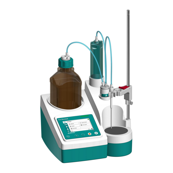
■■■■■■■■■■■■■■■■■■■■■■ Overview 1 Overview Product description The Eco Dosimat is a dosing device for universal use that is equipped with the following functional units: Built-in magnetic stirrer ■ Dosing unit with exchangeable cylinder unit ■ Separate Manual Dosing Controller ■... -
Page 10: Product Versions
(see example): Figure 1 Type plate (example) (01) = External article number (21) = Serial number (240) = Metrohm article number About the documentation NOTICE Please read through this documentation carefully before putting the product into operation. The documentation contains important information and warnings that must be followed for safe operation of the product. -
Page 11: Additional Information
Properties in the software. [Continue] Button or key Additional information Additional information concerning the topic can be found: in the Metrohm information portal on the Internet ■ https://guide.metrohm.com 1.4.1 Accessories Up-to-date information on the scope of delivery and optional accessories for your product can be found on the Internet. -
Page 12: Safety
Product safety ■■■■■■■■■■■■■■■■■■■■■■ 2 Safety Product safety This product exhibited no flaws in terms of technical safety at the time it left the factory. To preserve this status and ensure non-hazardous opera- tion of the product, the following instructions must be observed carefully. Hazard levels The following warning messages indicate the severity of the danger and its possible effects. -
Page 13: Warning Symbols
■■■■■■■■■■■■■■■■■■■■■■ Safety CAUTION Health hazards or severe property damage Warns of dangerous situations or unsafe actions that could result in moderate injuries or considerable property damage. Lists measures to avoid hazard. Warning symbols Make sure that any additional hazard symbols are marked on the product for your operation of the product. -
Page 14: Intended Use
– Warning of dangerous optical radiation Intended use Metrohm products are used for the analysis and handling of chemicals. Usage therefore requires the user to have basic knowledge and experience in handling chemicals. Knowledge regarding the application of fire preven- tion measures prescribed for laboratories is also mandatory. -
Page 15: Danger From Electrical Potential
■ sockets) against moisture. If you suspect that moisture has gotten into the product, discon- ■ nect the product from the energy supply. Then notify Metrohm Service. Only personnel who have been issued Metrohm qualification may ■ perform service and repair work on electrical and electronic com- ponents. -
Page 16: Danger From Biological Substances
If the product is used for biological hazardous substances, it must be marked in accordance with regulations. In case of a return shipment to Metrohm or a Metrohm Service partner, the product or product component has to be decontaminated and the hazard symbol for biological hazardous substances must be removed. -
Page 17: Danger From Careless Transport
■■■■■■■■■■■■■■■■■■■■■■ Safety 2.5.5 Danger from careless transport WARNING Risk of injury from careless transport Injuries from spilled chemical and/or biological substances, falling parts and pieces of broken glass. Remove loose parts (e.g. sample racks, sample vessels, bottles) ■ before transport. Remove liquids. -
Page 18: Personnel Requirement
Personnel requirement ■■■■■■■■■■■■■■■■■■■■■■ Spare parts must meet the technical requirements established by the ■ manufacturer. Original spare parts always meet these requirements. Personnel must be familiar with this safety-relevant information and it ■ must be available for consultation at all times. Personnel requirement Only qualified personnel may operate the present product. -
Page 19: Functional Description
■■■■■■■■■■■■■■■■■■■■■■ Functional description 3 Functional description System overview 3.1.1 Signals The status display uses flashing patterns to display the operating status of the instrument. Table 2 Status display Signal Flashing pat- Meaning tern LED lights up Ready for operation green LED flashes In operation / Waiting green (slowly) - Page 20 System overview ■■■■■■■■■■■■■■■■■■■■■■ Designation Short name Ethernet RJ-45 Connector for an Eco Dosimat for tandem mode Remote D-Sub Connector for instruments with remote interface (e.g. Manual Dosing Controller) Power OUT Mini DIN Power IN Mini DIN Connector for the energy supply...
-
Page 21: Overview
■■■■■■■■■■■■■■■■■■■■■■ Functional description Overview Figure 2 Eco Dosimat – Front Bottle holder Space for cylinder unit Flat stopcock Stand attachment Magnetic stirrer Status display, touch screen and con- trol bar ■■■■■■■■... - Page 22 Overview ■■■■■■■■■■■■■■■■■■■■■■ Figure 3 Eco Dosimat – Rear Type plate USB connector (USB 1 and USB 2) Ethernet connector (RJ-45) Remote connector "Power OUT" connector "Power IN" connector ■■■■■■■■...
- Page 23 ■■■■■■■■■■■■■■■■■■■■■■ Functional description Figure 4 Eco Dosimat – Accessories Cylinder unit Tubing connections Support rod Electrode holder Guide sleeve Clamping ring Buret tip Amber glass bottle with GL 45 thread Clip for SGJ 14/15 10 Bottle cap 11 Threaded stopper 12 Adsorber tube ■■■■■■■■...
- Page 24 Overview ■■■■■■■■■■■■■■■■■■■■■■ Figure 5 Eco Dosimat – Peripherals Printer Q3X (opt. accessory) USB flash drive (opt. accessory) Ethernet cable (opt. accessory) Manual Dosing Controller Power supply unit ■■■■■■■■...
-
Page 25: Dosing Unit
■■■■■■■■■■■■■■■■■■■■■■ Functional description 3.2.1 Dosing unit Figure 6 Dosing unit – Overview Cylinder unit Push rod (dosing drive) Flat stopcock ■■■■■■■■... - Page 26 Overview ■■■■■■■■■■■■■■■■■■■■■■ 3.2.1.1 Cylinder unit Figure 7 Cylinder unit – Overview Light protection Dosing cylinder Piston with sealing lips and piston rod Mounting ring ■■■■■■■■...
- Page 27 ■■■■■■■■■■■■■■■■■■■■■■ Functional description 3.2.1.2 Flat stopcock Figure 8 Flat stopcock – Overview Connector for the tubing connection to Connector for the tubing connection to the bottle the cylinder unit Connector for the tubing connection to Switching lever the buret tip ■■■■■■■■...
-
Page 28: Manual Dosing Controller
Overview ■■■■■■■■■■■■■■■■■■■■■■ 3.2.2 Manual Dosing Controller Figure 9 Manual Dosing Controller – Overview Dosing key [GO] Status LED Stop/Fill key [FILL] Connector plug ■■■■■■■■... -
Page 29: Bottle Unit
■■■■■■■■■■■■■■■■■■■■■■ Functional description 3.2.3 Bottle unit Figure 10 Bottle unit – Overview Cannula Threaded stopper Bottle cap Amber glass bottle with GL 45 thread Clip for SGJ 14/15 Adsorber tube Function 3.3.1 Magnetic stirrer The magnetic stirrer ensures that the sample is well mixed. The stirring rate can be adjusted depending on the amount and viscosity of the sam- ple. -
Page 30: Manual Dosing Controller
Function ■■■■■■■■■■■■■■■■■■■■■■ cylinder of the cylinder unit and is responsible for accurate dosing of the solution. The flat stopcock switches between filling and emptying the dosing cylin- der of the cylinder unit. Once the cylinder unit is put into place, the dosing drive and the flat stop- cock handle the following functions: Raising and lowering the piston: ■... -
Page 31: Indicators And Controls
■■■■■■■■■■■■■■■■■■■■■■ Functional description Figure 11 Manual Dosing Controller – Function Dosing key [GO] Status LED Stop/Fill key [FILL] Indicators and controls Indicators Figure 12 Indicators Status display Status indicator ■■■■■■■■... - Page 32 Indicators and controls ■■■■■■■■■■■■■■■■■■■■■■ Control bar Figure 13 Control bar keys On/Off Increase dosing rate Reduce dosing rate Stop Start Magnetic stirrer – Controls The stirring rate can be adjusted in the Stirrer work area. NOTICE The most recently used stirring rate will be used again when the instrument is switched on.
- Page 33 ■■■■■■■■■■■■■■■■■■■■■■ Functional description Figure 14 Stirring rate – Controls Stirrer work area Reduce stirring rate Increase stirring rate Start magnetic stirrer If the stirrer is in operation, then the Stop button will be displayed. Display – Controls The brightness of the display can be adjusted on the start page in the Sys- tem ▶...
-
Page 34: Interfaces And Connectors
Interfaces and connectors Figure 16 Interfaces and connectors Ethernet Connect USB flash drive, printer, balance, Remote control via local network. Connect etc. Eco Dosimat for tandem mode Remote Power IN Connect Manual Dosing Controller Connect power supply unit (6.2107.100) ■■■■■■■■... -
Page 35: Remote Interface
Pin assignment of the remote interface Figure 17 Pin assignment of remote socket and remote plug The above figure of the pin assignment applies to all Metrohm instru- ments with 9-pin D-Sub remote connector. Table 5 Inputs and outputs of the remote interface Pin no. - Page 36 Remote interface ■■■■■■■■■■■■■■■■■■■■■■ Outputs Open Collector > 200 ms active = low, inactive = high = 20 mA, V = 40 V +5 V: maximum load = 20 mA Status diagrams of the remote interface EOD = End of Determination Dosing mode DOS Ready/EOD OUTPUT 0...
- Page 37 ■■■■■■■■■■■■■■■■■■■■■■ Functional description Ready/EOD OUTPUT 0 OUTPUT 1 OUTPUT 2 OUTPUT 3 Error OUTPUT 4 Start INPUT 0 Stop INPUT 1 Figure 20 Remote status diagram XDOS, without error event Ready/EOD OUTPUT 0 OUTPUT 1 OUTPUT 2 OUTPUT 3 Error OUTPUT 4 Start INPUT 0...
-
Page 38: Remote Control
Remote control ■■■■■■■■■■■■■■■■■■■■■■ Ready/EOD OUTPUT 0 OUTPUT 1 OUTPUT 2 OUTPUT 3 Error OUTPUT 4 Start INPUT 0 Stop INPUT 1 Figure 23 Remote status diagram CNTD, with error event Remote control The instrument can be remote controlled via an Ethernet connection. An RJ-45 plug with Local Area Network (LAN) is required for this. - Page 39 ■■■■■■■■■■■■■■■■■■■■■■ Functional description Command Function Comment Scan instrument sta- Acknowledgements: Ready;0, Busy;0 or Hold;0 (0 = no message). If a message on the instrument requires the interaction of the user, the acknowl- edgement of the status scan displays the corresponding message number. Example: Busy;010-119 = "Check buret unit"...
-
Page 40: Transport And Storage
Checking the delivery ■■■■■■■■■■■■■■■■■■■■■■ 4 Transport and storage Checking the delivery Immediately upon arrival of the merchandise, check the shipment against the delivery note to ensure completeness and absence of damage. Storing the packaging The product is supplied in extremely protective packaging together with the separately packed accessories. -
Page 41: Installation
■ sockets) against moisture. If you suspect that moisture has gotten into the product, discon- ■ nect the product from the energy supply. Then notify Metrohm Service. Only personnel who have been issued Metrohm qualification may ■ perform service and repair work on electrical and electronic com- ponents. - Page 42 Preparing the assembly ■■■■■■■■■■■■■■■■■■■■■■ Connecting the power cord Figure 24 Rear of the instrument – Connecting the power cord NOTICE The flat side of the plug of the power supply unit must face downwards. Connect the power supply unit to the Power IN connector. Note the orientation (see figure).
-
Page 43: Switching The Instrument On And Off
■■■■■■■■■■■■■■■■■■■■■■ Installation Switching the instrument on and off Switching on the instrument Prerequisite The power cord is connected. 1 Press the key. The instrument is initialized and a system test is performed. If the Beep parameter is activated in the system settings of the parameters, then a beep will be heard after switch-on. -
Page 44: Mounting The Cylinder Unit
Mounting the cylinder unit ■■■■■■■■■■■■■■■■■■■■■■ Mounting the cylinder unit Preparing the instrument Prerequisite The instrument is switched on. To mount the cylinder unit, the piston rod must be pulled out of the dos- ing cylinder by approx. 6 mm. If necessary, pull the piston carefully out of the dosing cylinder with the 6.1546.040 piston tool. -
Page 45: Mounting The Support Rod
■■■■■■■■■■■■■■■■■■■■■■ Installation Mounting the support rod Mounting the support rod Procedure 1 Screw the support rod onto the stand attachment. The clamping ring and the electrode holder can now be mounted to the support rod. NOTICE The clamping ring is used as the lower stop for the electrode holder. -
Page 46: Preparing The Bottle Unit
Preparing the bottle unit ■■■■■■■■■■■■■■■■■■■■■■ Preparing the bottle unit Preparing the bottle cap with adsorber tube 1 Insert the cannula. 2 Insert the threaded stopper. 3 Fill the adsorber tube with a suitable sorbent: Molecular sieve for water sensitive samples. ■... -
Page 47: Mounting The Tubing Connections
■■■■■■■■■■■■■■■■■■■■■■ Installation Assembling and setting up the bottle 1 Set the bottle in the bottle holder. 2 Screw the prepared bottle cap onto the bottle and tighten it by hand. Mounting the tubing connections The tubing connections connect the bottle cap with the flat stopcock, the cylinder unit and the buret tip. - Page 48 Mounting the tubing connections ■■■■■■■■■■■■■■■■■■■■■■ Mounting the tubing connections and the buret tip Prerequisite: The cylinder unit, electrode holder and bottle unit are set up. ■ 1 Screw the 6.1805.090 tubing securely to the cylinder unit and to the flat stopcock. 2 Screw the 6.1805.090 tubing securely to the bottle unit and to the flat stopcock.
-
Page 49: Start-Up
■■■■■■■■■■■■■■■■■■■■■■ Start-up 6 Start-up Switching the instrument on and off Switching on the instrument Prerequisite The power cord is connected. 1 Press the key. The instrument is initialized and a system test is performed. If the Beep parameter is activated in the system settings of the parameters, then a beep will be heard after switch-on. -
Page 50: Setting The Language, Date And Time
Setting the language, date and time ■■■■■■■■■■■■■■■■■■■■■■ Setting the language, date and time Date, time, language and dialog type can be set once the instrument has been correctly installed. Setting the language Prerequisite: The instrument is switched on. ■ 1 On the Start page, open the System ▶ Settings menu. 2 Click on the Language button. -
Page 51: Setting The Dialog Type
■■■■■■■■■■■■■■■■■■■■■■ Start-up Setting the dialog type The user rights can be restricted with the [Dialog type] input field: Dialog type Expert (default value) ■ In the dialog type Expert, all the user settings are available. Dialog type Routine ■ In the dialog type Routine, the availability of the settings is restricted. The System and Methods menus as well as the Parameters work area can only be opened with a password. - Page 52 Setting the dialog type ■■■■■■■■■■■■■■■■■■■■■■ 2 Click in the input field. A keyboard appears. 3 Enter the password METROHM9100 and confirm with [OK]. The password is displayed in encrypted form. 4 Confirm the entry with OK. The System menu opens. The menu is now ready for use. If you exit the System menu at this point, the instrument will remain in the Routine mode.
-
Page 53: Operation And Control
■■■■■■■■■■■■■■■■■■■■■■ Operation and control 7 Operation and control Indicators and controls Figure 26 Status display, touch screen and control bar Status display Touch screen Control bar The status display indicates the operating status of the instrument. The touch screen is used to set and control the instrument as well as to display results and other information. -
Page 54: Switching The Instrument On And Off
Switching the instrument on and off ■■■■■■■■■■■■■■■■■■■■■■ Switching the instrument on and off Switching on the instrument Prerequisite The power cord is connected. 1 Press the key. The instrument is initialized and a system test is performed. If the Beep parameter is activated in the system settings of the parameters, then a beep will be heard after switch-on. -
Page 55: User Interface - Brief Description
The following work areas can be selected: Eco Dosimat The start page with access to the functions: Methods ■... - Page 56 User interface – Brief description ■■■■■■■■■■■■■■■■■■■■■■ Print reports ■ Direct DOS ■ Method selection bar ■ Sample data Access to the functions: Sample size ■ Unit ■ ■ ■ Parameters Access to the functions: Solutions ■ Dosing parameters ■ Calculation ■...
- Page 57 ■■■■■■■■■■■■■■■■■■■■■■ Operation and control Keyboards – Input of text and numbers An appropriate keyboard is called up, depending on the type of input. Figure 28 Keyboard (example: lower-case characters) Input field Delete input field Backspace Cancel input (close window) Apply entry Forwards in the input field Backwards in the input field Space...
-
Page 58: Manual Control
Manual control ■■■■■■■■■■■■■■■■■■■■■■ Backwards in the input field Default value and limit values Algebraic sign change Help texts Help texts are available for selection bars and input fields. Clicking on a selection bar or input field for at least 3 seconds calls up the corresponding help text. - Page 59 If you suspect that chemical substances have gotten into the ■ instrument, disconnect the instrument from the energy supply. Then, notify Metrohm Service. Emptying, disassembling and mounting 1 On the start page, open the Manual control menu. Click on the [Exchange cylinder unit] button.
- Page 60 Manual control ■■■■■■■■■■■■■■■■■■■■■■ Make sure that the tubing from the bottle cap is removed. ■ [Continue] ■ The message Exchanging cylinder unit... appears and the piston is lowered down to the height at which the cylinder unit can be disas- sembled.
-
Page 61: Preparing The Buret (Prep)
■■■■■■■■■■■■■■■■■■■■■■ Operation and control The push rod moves the piston into the basic position. Make sure that the cylinder unit has been mounted correctly. ■ [Continue] ■ 8 [Continue] NOTICE Make sure that the value for the cylinder volume in the System menu is the same as the volume of the mounted cylinder unit. -
Page 62: Operating The Magnetic Stirrer
Manual control ■■■■■■■■■■■■■■■■■■■■■■ The piston rises and sinks and the cylinder empties and fills in 2 cycles. Then, the buret is prepared. 7.4.3 Operating the magnetic stirrer Switching the stirrer on and off Procedure 1 Add the stirring bar to the sample vessel. Open the Stirrer work area: The controls for the magnetic stirrer appear: 3 Switching on the stirrer... -
Page 63: Direct Dosing (Direct Dos)
■■■■■■■■■■■■■■■■■■■■■■ Operation and control With each click, the stirring rate is reduced by one step. The current stirring rate is displayed. 2 Increasing the stirring rate in steps Click on the button repeatedly until the desired stirring rate has been reached. With each click, the stirring rate is increased by one step. -
Page 64: Methods
Methods ■■■■■■■■■■■■■■■■■■■■■■ Methods Definition A method determines how dosing is carried out. The dosing mode, the solution used and further parameters are defined in a method. Methods are saved under a freely selectable method name. A method name consists of a maximum of 24 characters. Method selection bar The method selection bar on the start page shows the method that has been loaded. -
Page 65: Using And Managing Methods
■■■■■■■■■■■■■■■■■■■■■■ Operation and control Method list The [Method] button on the start page shows a list of all the saved meth- ods. Methods can be created, exported and deleted here. Figure 31 Method list (example) A scroll bar appears if the list is longer. Dosing mode Each method is based on a dosing mode. - Page 66 Methods ■■■■■■■■■■■■■■■■■■■■■■ Create new method ■ Delete method – Remove the method from the method list. ■ Export method – Print out the method or save it to a USB flash drive. ■ Import method – Add a method from a USB flash drive to the ■...
- Page 67 ■■■■■■■■■■■■■■■■■■■■■■ Operation and control The method that you want to save is loaded in the method selection bar. The method is marked [New] or [Modified]. 1 Save the method: An input field for the name appears. 2 Click on the input field. A keyboard appears.
- Page 68 Methods ■■■■■■■■■■■■■■■■■■■■■■ NOTICE If modifications on the method that was loaded before have not been saved, the following warning appears: Store method: The modifications of the current method have not been saved. Do you want to load the method anyway? [Yes] –...
- Page 69 ■■■■■■■■■■■■■■■■■■■■■■ Operation and control 3 Delete the highlighted method: The warning Delete method appears. 4 Confirm deleting: [Delete] The deleted method is no longer available in the method list. Exporting a method Procedure 1 Connect the USB flash drive to the instrument. 2 On the start page, click on the [Methods] button.
- Page 70 Methods ■■■■■■■■■■■■■■■■■■■■■■ NOTICE If a method with the same name already exists on the USB flash drive, then the following warning appears: Store method: Method name already exists. Do you want to overwrite the name?. [Yes]: The method on the USB flash drive will be overwritten. ■...
-
Page 71: Sample Data
■■■■■■■■■■■■■■■■■■■■■■ Operation and control Once the message has disappeared, the method is saved to the instrument. NOTICE If a method with the same name already exists on the instru- ment, then the following warning appears: Store method: Method name already exists. Do you want to overwrite the name?. - Page 72 Default value: g Applying the sample size from the balance Prerequisite A Sartorius balance is connected to the Eco Dosimat via the USB inter- ■ face. The balance uses the PC text format protocol for the USB interface.
-
Page 73: System - Configuration
Operation and control Print the measured sample size on the balance: Print The balance sends the sample size and the unit to the Eco Dosimat. System – Configuration The system configuration of the Eco Dosimat is in the System menu with... -
Page 74: Instrument Settings
Figure 34 Page 2/2 7.7.1 Instrument settings All general instrument settings for the Eco Dosimat are in the Sys- tem ▶ Settings menu. Adjusting instrument settings 1 On the start page, open the System ▶ Settings menu. 2 Adjust the settings. Pay attention to the following notes:... - Page 75 ■■■■■■■■■■■■■■■■■■■■■■ Operation and control Instrument name Enter the instrument name. If an instrument name is defined, it will be dis- played in the report. PREP warning If the PREP warning is activated, the message Prepare buret (PREP) appears in the following cases: After the instrument is switched on.
-
Page 76: Managing Solutions
System – Configuration ■■■■■■■■■■■■■■■■■■■■■■ 7.7.2 Managing solutions A solution is the liquid that is dosed into the sample beaker or dosed to the sample. The System ▶ Solutions menu is used to manage up to 20 different sol- utions. Figure 37 Solutions menu with the solution list (example) Functions for managing the solution list: Create new solution... - Page 77 ■■■■■■■■■■■■■■■■■■■■■■ Operation and control Figure 38 Solution parameters page 1/2 Name ■ The name of the solution is used for unique identification. Monitoring ■ Switch the titer monitoring on or off. Titer unit ■ Unit of the titer. ■ Date titer det. ■...
- Page 78 System – Configuration ■■■■■■■■■■■■■■■■■■■■■■ Time interval ■ This parameter is visible only when Monitoring = On. When you start a method, you will be notified if this time interval (in days) has already elapsed. You can then select whether or not you would still like to start the method.
- Page 79 ■■■■■■■■■■■■■■■■■■■■■■ Operation and control Figure 41 Solution list 2 Highlight the desired solution. 3 Edit the highlighted solution: 4 Change the solution parameters if needed. Deleting the solution 1 On the start page, open the System ▶ Solutions menu. Figure 42 Solution list 2 Highlight the solution to be deleted.
-
Page 80: Managing External Devices
Configure the serial interface: Start page ▶ System ▶ COM port set- tings The parameters set for the RS-232 interface on the balance must match those on the Eco Dosimat. 7.7.4 File management In the System ▶ File management menu, a system backup (all data and settings) can be created. - Page 81 ■■■■■■■■■■■■■■■■■■■■■■ Operation and control NOTICE A USB flash drive must be connected. If no USB flash drive is connec- ted, the message Connect USB flash drive will appear. Figure 44 File management menu with the method list (example) File management functions: Import Import the highlighted method from the USB flash drive.
-
Page 82: Instrument Diagnostics
System – Configuration ■■■■■■■■■■■■■■■■■■■■■■ Importing a method NOTICE Only methods that are stored in the Files folder on the USB flash drive are displayed in the method list. 1 On the start page, open the System ▶ File management menu. 2 Highlight the desired method. -
Page 83: Ethernet Settings
Export an error log to the USB flash drive: ■ 7.7.6 Ethernet settings Start page ▶ System ▶ Ethernet settings Example of usage: Connection with a second Eco Dosimat for tandem operation. Mode This network configuration can be done manually or automatically. Selection: Static ■... -
Page 84: Changing The Password
System – Configuration ■■■■■■■■■■■■■■■■■■■■■■ 7.7.8 Changing the password With the password for the Expert dialog type you can control access to the menus System and Methods as well as the Parameters work area. Changing the password for the Expert dialog type: 1 On the Start page, open the System ▶... -
Page 85: Com Port Settings
■■■■■■■■■■■■■■■■■■■■■■ Operation and control 7.7.9 COM port settings System ▶ COM port settings When using a balance with serial interface, adjust the corresponding set- tings. The parameters set for the RS-232 interface on the balance must match those on the instrument. NOTICE Use the 6.2148.050 USB/RS-232 Converter. -
Page 86: Dosing (Dos And Xdos)
Dosing (DOS and XDOS) ■■■■■■■■■■■■■■■■■■■■■■ Parity Type of parity testing. Selection: Even ■ None ■ ■ Default value: None Handshake Type of the data transfer protocol. Selection: Hardware ■ Software ■ none ■ Default value: Hardware NOTICE If communication problems occur, set the parameter Handshake to Software, and make another attempt. - Page 87 ■■■■■■■■■■■■■■■■■■■■■■ Operation and control Dosing ramp ■ The dosing rate and the dosing ramp are specified. 2 Preparing the sample (if necessary) NOTICE For semi-automatic titrations: Calculate the amount of the sam- ple so that it results in titrant consumption of 10 to 90% of the cylinder volume.
- Page 88 Dosing (DOS and XDOS) ■■■■■■■■■■■■■■■■■■■■■■ Dosing continuously ■ (Dosing parameter Mode = Dosing ramp) Press the key on the instrument or on the dosing controller for as long as dosing should take place. Pausing the dosing: Release the key. Continuing the dosing: Press the key again for as long as dos- ing should take place.
- Page 89 ■■■■■■■■■■■■■■■■■■■■■■ Operation and control Depending on the parameter settings, the instrument automatically calculates the result and prints out a report. The report for the cur- rent dosing can be printed out manually if necessary: Start page ▶ Print reports ▶ Results The result of the calculation is shown under the volume display.
- Page 90 Dosing (DOS and XDOS) ■■■■■■■■■■■■■■■■■■■■■■ 4 Switching the magnetic stirrer on Turn on the stirrer in the work area if required. 5 Starting the dosing Make sure that the buret tip points into a sample vessel or dosing vessel. Press the key on the instrument or on the dosing controller.
- Page 91 ■■■■■■■■■■■■■■■■■■■■■■ Operation and control If the Auto fill dosing parameter is switched off: Repeat the dosing: key. The dosing parameter Clear volume ■ display determines whether the volume display should continue counting or start at zero again. Fill dosing cylinder manually: ■...
- Page 92 Dosing (DOS and XDOS) ■■■■■■■■■■■■■■■■■■■■■■ NOTICE If the ongoing dosing step is finished while an editing dialog is open (e.g. of the sample size), then this will be closed automati- cally and the live status will be displayed. The value entered must be entered once more.
-
Page 93: Carrying Out Tandem Dosing (Xdos)
Carrying out tandem dosing (XDOS) If continuous dosing without interruption is required, then the tandem mode can be selected. It requires 2 Eco Dosimat instruments. NOTICE For tandem operation, 2 dosing cylinders of the same cylinder volume have to be used. - Page 94 Carrying out tandem dosing (XDOS) ■■■■■■■■■■■■■■■■■■■■■■ The principle of tandem dosing Figure 48 Tandem operation The two Dosimats operate alternately during dosing. If the dosing cylinder of one Dosimat needs to be filled, then the second Dosimat will take over the control of the dosing.
- Page 95 ■■■■■■■■■■■■■■■■■■■■■■ Operation and control Establishing a LAN connection 1 Connecting the Dosimats Prepare 2 Dosimats with the same cylinder volume. Connect the Ethernet connectors of the two Dosimats with a net- work cable. 2 Adjusting the Ethernet settings On the tandem master: Start page ▶...
- Page 96 Carrying out tandem dosing (XDOS) ■■■■■■■■■■■■■■■■■■■■■■ Buret setup: [Tandem slave] ■ If the Invalid tandem master IP address warning appears: ■ Continue Enter the valid tandem master IP address: ■ Tandem master IP address: 192.168.0.51 (example) The tandem slave establishes a connection with the tandem master. Once the connection has been established, the following message appears for a brief moment: Connected to tandem master.
- Page 97 ■■■■■■■■■■■■■■■■■■■■■■ Operation and control Figure 49 Live-Status – Dosing mode XDOS The two Dosimats operate alternately during dosing. The instrument that is currently dosing displays the total dosed volume. 7 Live modifications Make live modifications if necessary: Edit the sample data of the ongoing dosing process ■...
-
Page 98: Creating Solutions (Cntd)
1 Loading the method Load the required CNTD method. Define the method parameters: Solutions ■ We, at Metrohm, always recommend selecting the solution. Content definitions ■ Define the target solution. 2 Preparing the sample Weigh in or measure the sample in a sample vessel. - Page 99 ■■■■■■■■■■■■■■■■■■■■■■ Operation and control Figure 50 Calculated target volume 5 Starting the dosing Press the key on the instrument or on the dosing controller again if the calculated target volume seems plausible. Dosing is in progress. The instrument shows the Live status work area: Figure 51 Live-Status –...
-
Page 100: Printing Reports
Printing reports ■■■■■■■■■■■■■■■■■■■■■■ 7 Ending the dosing The dosing stops as soon as the target volume has been reached. Dosing can be canceled at any time with the key if necessary. After ending, the instrument fills the dosing cylinder. Depending on the parameter settings, the instrument automatically prints a report. -
Page 101: Parameters
The dosing mode CNTD (content dosing) is suitable for producing stand- ard solutions and other solutions. Based on the sample size of the starting substance (solid or stock solution) and the specified target concentration, the Eco Dosimat automatically determines the volume of solvent to be dosed. ■■■■■■■■... -
Page 102: Dosing In Steps (Dos)
Solutions Parameters ▶ Solutions Select solution Selection of the solution from the solution list. We, at Metrohm, always recommend selecting the solution. At the start of the determination, the instrument checks whether the cylin- der volume of the selected solution corresponds to the cylinder volume of the mounted buret. - Page 103 ■■■■■■■■■■■■■■■■■■■■■■ Operation and control 7.12.1.2 Dosing parameters Parameters ▶ Dosing parameters Under [Dosing parameters], you can control the dosing procedure of the loaded DOS method. NOTICE The maximum dosing rate and maximum filling rate depend on the cylinder volume (see table). If volatile solvents/solutions or solutions with a high viscosity are used, the dosing rate must be reduced accordingly so that the dosing unit is not overloaded.
- Page 104 Parameters ■■■■■■■■■■■■■■■■■■■■■■ Selection: Dosing ramp: Dosing with uniform dosing rate (Dosing ramp = 0 s) ■ or with slowly increasing dosing rate. Volume: Dosing a fixed volume per dosing step. ■ Default value: Dosing ramp Dosing ramp This parameter is only active if Mode = Dosing ramp. The dosing ramp is a gentle increase in the dosing rate at the time of the start of a dosing step.
- Page 105 ■■■■■■■■■■■■■■■■■■■■■■ Operation and control Volume Dosed volume Blank Blank value Titer Titer of the solution used Conc. Concentration of the solution used Factor Factor Sample size Sample size. The sample size and associated unit can be specified under Sample data. Divisor Divisor NOTICE...
- Page 106 Parameters ■■■■■■■■■■■■■■■■■■■■■■ Selection: ■ ■ ■ ■ ■ ■ ■ mg/mL ■ ■ mol/L ■ ■ User-defined: A user-defined unit can be created. This will be added ■ to the selection list. The previous entry will be overwritten as soon as the new unit has been defined.
- Page 107 ■■■■■■■■■■■■■■■■■■■■■■ Operation and control Input range 0 to 1,000,000 mL Default value 0.0000 mL 7.12.1.4 Reports Parameters ▶ Reports The reports that will be printed out automatically or saved as a PDF report after a determination are defined under [Reports]. Results The result report contains the calculated result and additional specifica- tions.
-
Page 108: Extended Dosing (Xdos)
Solutions Parameters ▶ Solutions Select solution Selection of the solution from the solution list. We, at Metrohm, always recommend selecting the solution. At the start of the determination, the instrument checks whether the cylin- der volume of the selected solution corresponds to the cylinder volume of the mounted buret. - Page 109 ■■■■■■■■■■■■■■■■■■■■■■ Operation and control 7.12.2.2 Dosing parameters Parameters ▶ Dosing parameters Under [Dosing parameters], you can control the dosing procedure of the loaded XDOS method. Dosing criteria Selection of the preset dosing criteria. If dosing without interruption is required, the instrument needs to be operated in tandem mode. Selection: Volume/rate: The volume specified is dosed at the selected dosing ■...
- Page 110 Parameters ■■■■■■■■■■■■■■■■■■■■■■ Dosing rate This parameter is only active if Dosing criteria = Volume/rate or Rate/ time. The rate at which dosing takes place. Input range 0.020 to Max. mL/min Additional selection: Max. = maximum dosing rate. Default value: Max. Filling rate Rate at which the dosing cylinder is filled.
- Page 111 ■■■■■■■■■■■■■■■■■■■■■■ Operation and control Selection: Off / On Default value: On Clear the volume display This parameter is active only when Auto fill = Off. Selection: Off: The volume display continues the counting during repeated dos- ■ ing. The volume display only starts at 0.0000 mL again after the dosing cylinder has been filled manually.
-
Page 112: Creating Solutions (Cntd)
Parameters ■■■■■■■■■■■■■■■■■■■■■■ Results The result report contains the calculated result and additional specifica- tions. Selection: Off / On Default value: Off Parameters All of the parameters of the current method are shown in the parameter report. Selection: Off / On Default value: Off NOTICE The printer for the report data from above is defined under Start... - Page 113 ■■■■■■■■■■■■■■■■■■■■■■ Operation and control The dosing mode CNTD (content dosing) is suitable for producing stand- ard solutions and other solutions. Based on the sample size of the starting substance (solid or stock solution) and the specified target concentration, the instrument automatically determines the volume of solvent to be dosed.
- Page 114 Solutions Parameters ▶ Solutions Select solution Selection of the solution from the solution list. We, at Metrohm, always recommend selecting the solution. At the start of the determination, the instrument checks whether the cylin- der volume of the selected solution corresponds to the cylinder volume of the mounted buret.
- Page 115 ■■■■■■■■■■■■■■■■■■■■■■ Operation and control NOTICE The maximum dosing rate and maximum filling rate depend on the cylinder volume (see table). If volatile solvents/solutions or solutions with a high viscosity are used, the dosing rate must be reduced accordingly so that the dosing unit is not overloaded.
- Page 116 Parameters ■■■■■■■■■■■■■■■■■■■■■■ Input range 0.01 to 99,999.9 mL Additional selection: Off = no volume limit. Default value: Off 7.12.3.3 Definition of the target solution Parameters ▶ Content definitions The required target solution of the loaded CNTD method can be defined under [Content definitions].
- Page 117 ■■■■■■■■■■■■■■■■■■■■■■ Operation and control Input range 0.000000001 to 9,999,999,999 g/mL Default value: 1.0 g/mL Factor Multiplication factor for the calculation of the volume to be dosed. The factor can be used in general as a correction factor, e.g. for compensating for volume contraction or for specifying the starting concentration.
- Page 118 Parameters ■■■■■■■■■■■■■■■■■■■■■■ NOTICE The printer for the report data from above is defined under Start page ▶ System ▶ External devices ▶ Printer. If [PDF] is selected as printer and at least one option is activated, ■ then the report contains the complete data. If a different printer is selected, then the report contains the data ■...
-
Page 119: Maintenance
Only perform maintenance work that is described in this instruction. Con- tact the Metrohm service for further maintenance and repairing works. Disconnect the product from the power grid prior to any maintenance and cleaning. -
Page 120: Maintenance Agreement
■ sockets) against moisture. If you suspect that moisture has gotten into the product, discon- ■ nect the product from the energy supply. Then notify Metrohm Service. Only personnel who have been issued Metrohm qualification may ■ perform service and repair work on electrical and electronic com- ponents. -
Page 121: Cleaning The Product
■ sockets) against moisture. If you suspect that moisture has gotten into the product, discon- ■ nect the product from the energy supply. Then notify Metrohm Service. Only personnel who have been issued Metrohm qualification may ■ perform service and repair work on electrical and electronic com- ponents. -
Page 122: Performing Maintenance On The Cylinder Unit
■■■■■■■■■■■■■■■■■■■■■■ NOTICE If the suspicion arises that liquids have found their way into the product, disconnect the product from the power grid and con- tact your Metrohm Service. NOTICE Water or ethanol can be used as a cleaning medium. NOTICE The connectors at the rear of the product must only be cleaned with a dry cloth. - Page 123 If you suspect that chemical substances have gotten into the ■ instrument, disconnect the instrument from the energy supply. Then, notify Metrohm Service. Maintenance steps Emptying the cylinder unit as far as possible and removing it ■...
- Page 124 Cleaning the product ■■■■■■■■■■■■■■■■■■■■■■ NOTICE It is normally not necessary to remove the mounting ring out of the light protection or the screw nipple on the dosing cylinder for clean- ing. The parts can be cleaned while still in their pre-mounted state. Push the dosing cylinder out of the light protection from above.
- Page 125 ■■■■■■■■■■■■■■■■■■■■■■ Maintenance Are scratches visible on the piston surface? ■ Is any unevenness visible on the sealing lips of the piston? ■ If any of these defects is visible, replace the entire cylinder unit. Assembling the cylinder unit Required accessories: 6.2803.010 paraffin grease ■...
-
Page 126: Mounting The Cylinder Unit
Cleaning the product ■■■■■■■■■■■■■■■■■■■■■■ 8.3.2 Mounting the cylinder unit Mounting the cylinder unit Prerequisite The instrument is switched on. The [Exchange cylinder unit] process was executed up to the point when the cylinder unit can be removed from the instrument. The maintenance has been carried out professionally or a new cylinder unit is ready to be mounted. -
Page 127: Checking And Replacing Product Parts
■■■■■■■■■■■■■■■■■■■■■■ Maintenance Make sure that the cylinder unit has been mounted correctly. [Continue] 6 [Continue] NOTICE Make sure that the value for the cylinder volume in the System menu is the same as the volume of the mounted cylinder unit. NOTICE Carry out the Prepare buret (PREP) command. -
Page 128: Checking The Indicators And Controls
■ sockets) against moisture. If you suspect that moisture has gotten into the product, discon- ■ nect the product from the energy supply. Then notify Metrohm Service. Only personnel who have been issued Metrohm qualification may ■ perform service and repair work on electrical and electronic com- ponents. -
Page 129: Displaying System Data
■■■■■■■■■■■■■■■■■■■■■■ Maintenance Displaying system data Display program version and instrument details: Start page ▶ Sys- tem ▶ About Figure 57 Program version and instrument details (example) Logs Show error log: Start page ▶ System ▶ Diagnosis ▶ Logs ■ Export an error log to the USB flash drive: ■... - Page 130 Resetting the system ■■■■■■■■■■■■■■■■■■■■■■ The instrument is switched off. ■ 1 Switching on the instrument Press the key. 2 Resetting the system Wait until the following text is displayed in the bottom line of the screen: Initializing, please wait... Once the text shown above appears, press the 3 keys simultaneously and hold for approx.
-
Page 131: Malfunctions And Troubleshooting
Malfunctions have to be solved directly on the product. If applicable, ■ this can be done with the help of the control software (e.g. initializa- tion, move to defined position, etc.). NOTICE Additional information can be found in the context-sensitive software help or on https://guide.metrohm.com. ■■■■■■■■... -
Page 132: Disposal
■■■■■■■■■■■■■■■■■■■■■■ 10 Disposal This product is covered by European Directive, WEEE – Waste Electrical and Electronic Equipment. The correct disposal of your old product will help to prevent negative effects on the environment and public health. More details about the disposal of your old product can be obtained from your local authorities, from waste disposal companies or from your local dealer. -
Page 133: Technical Specifications
■■■■■■■■■■■■■■■■■■■■■■ Technical specifications 11 Technical specifications 11.1 Ambient conditions Nominal function range +5 to +45 °C max. 80% relative humidity, non- condensing Storage +5 to +45 °C 11.2 Energy supply External power supply unit Input Nominal voltage range 100–240 VAC Frequency range 50–60 Hz Current... -
Page 134: Dimensions
Dimensions ■■■■■■■■■■■■■■■■■■■■■■ Current at the power supply unit 500 mA max. output current per channel Protection Internal fuse 1.5 A 11.3 Dimensions Measurements Width 286 mm Height without cylinder unit 220 mm with cylinder unit 358 mm with support rod 508 mm Depth 286 mm... -
Page 135: Connectors Specifications
Socket D-Sub 9-pin Ethernet CAT 6 Type Socket RJ-45 Cable type min. FFTP shielded Cable length max. 10 m from Metrohm acces- sories Type Socket type A Cable type shielded Cable length max. 5 m from Metrohm acces- sories ■■■■■■■■... -
Page 136: Display Specifications
Display specifications ■■■■■■■■■■■■■■■■■■■■■■ 11.6 Display specifications Display Type VGA color display Size approx. 4.3" diagonal Resolution 480 × 272 pixels Status display green 11.7 Operation specifications Touch panel Type resistive Resistance to chemicals resistant to the following chemicals (no visible changes after 24 h of dura- tion of action): ethanol... -
Page 137: Liquid Handling Specifications
■■■■■■■■■■■■■■■■■■■■■■ Technical specifications 11.9 Liquid handling specifications Cylinder unit Cylinder volume 5, 10, 20, 50 mL Dosing drive Dosing resolution 20,000 steps per cylinder vol- Dosing accuracy according to ISO/DIN 8655-3 Tubing Tubing nipple outer thread Inner diameter 2 mm Material fluorinated ethylene propylene...
Need help?
Do you have a question about the Eco Dosimat and is the answer not in the manual?
Questions and answers
can i have a electrical diagrame for dosimat plus 876 and checking voltage points