Table of Contents
Advertisement
Quick Links
Advertisement
Table of Contents

Related Manuals for Metrohm Eco KF Titrator


Summary of Contents for Metrohm Eco KF Titrator
- Page 1 Eco KF Titrator Product manual 8.1027.8001EN / 2021-08-27...
- Page 3 Metrohm AG Ionenstrasse CH-9100 Herisau Switzerland +41 71 353 85 85 info@metrohm.com www.metrohm.com Eco KF Titrator Firmware version 57.1027.0000 or higher Product manual 8.1027.8001EN / 2021-08-27...
- Page 4 Disclaimer Deficiencies arising from circumstances that are not the responsibility of Metrohm, such as improper storage or improper use, etc., are expressly excluded from the warranty. Unauthorized modifications to the product (e.g. conversions or attachments) exclude any liability on the part of the manufacturer for resulting damage and its consequences.
-
Page 5: Table Of Contents
Danger during transport of the product ........8 Design of warning messages ..........8 Meaning of warning signs ........... 9 3 Functional description Signals ................. 11 Eco KF Titrator – Overview ..........12 3.2.1 Dosing unit ................16 3.2.2 Bottle unit ................19 3.2.3... - Page 6 Table of contents ■■■■■■■■■■■■■■■■■■■■■■ Packaging ................29 5 Installation Setup location ..............30 Preparing the assembly ............30 Switching the instrument on and off ........ 32 Initial assembly of the cylinder unit ........33 Mounting the support rod ..........34 Mounting the volumetric Karl Fischer titration cell ..
- Page 7 ■■■■■■■■■■■■■■■■■■■■■■ Table of contents Results ................. 89 Printing reports ..............92 Parameters ................93 7.9.1 Conditioning ................. 93 7.9.2 Start conditions ..............95 7.9.3 Titration parameters .............. 97 7.9.4 Control parameters ..............99 7.9.5 Stop conditions ..............103 7.9.6 Calculation – Blank Ipol methods ......... 104 7.9.7 Calculation –...
-
Page 9: Overview
Overview 1 Overview Product description The Eco KF Titrator is an instrument with built-in stirrer used for volumetric water content determination. Conditioning is automatically carried out before and after the actual titration. Reagent dosing is controlled in such a way that a predefined endpoint is reached as quickly and precisely as pos- sible. -
Page 10: Product Versions
Solvent Pump assembly The required numbers for the customer service can be found on the type plate (see example): Figure 2 Type plate (example) (01) = External article number (21) = Serial number (240) = Metrohm article number ■■■■■■■■... -
Page 11: Symbols And Conventions
Method Names of parameters, menu items, tabs and dialog windows File ▶ New Menu path [Continue] Button or key Additional information Additional information concerning the topic can be found: in the Metrohm information portal on the Internet ■ https://guide.metrohm.com ■■■■■■■■... -
Page 12: Accessories
Accessories ■■■■■■■■■■■■■■■■■■■■■■ Accessories Up-to-date information on the scope of delivery and on optional accesso- ries can be found on the Metrohm website. Download this information as follows: Downloading the accessories list 1 Go to https://www.metrohm.com. 2 Enter the article number of the product (e.g. 2.1001.0010) into the search field. -
Page 13: Safety
Safety 2 Safety Intended use The Eco KF Titrator is designed for usage as a titrator in analytical labora- tories. Its main application field is volumetric Karl Fischer titration. This instrument is suitable for processing chemicals and flammable samples. Usage therefore requires the user to have basic knowledge and experience in handling chemicals. -
Page 14: Requirements For Operating Personnel
Always have maintenance work and repairs on electrical components ■ carried out by a regional Metrohm service representative. Disconnect the product from the energy supply immediately if at least ■ one of the following cases occurs: –... -
Page 15: Danger From Highly Flammable Substances
Dispose of chemically contaminated materials (e.g. cleaning material) in ■ accordance with regulations. Proceed as follows in case of a return shipment to Metrohm AG or a ■ regional Metrohm representative: – Decontaminate the product or product component. -
Page 16: Danger During Transport Of The Product
Design of warning messages ■■■■■■■■■■■■■■■■■■■■■■ 2.4.5 Danger during transport of the product Chemical or biological substances may be spilled during the transport of the product. Parts of the product may fall down or may be damaged. There is a risk of injury from chemical or biological substances and pieces of broken glass. -
Page 17: Meaning Of Warning Signs
■■■■■■■■■■■■■■■■■■■■■■ Safety WARNING Type or source of danger Consequences when not observing the notice: A serious injury that may result in death is probable. Measures to avoid the danger ■ CAUTION Type or source of danger Consequences when not observing the notice: A minor to moderate injury is probable. - Page 18 Meaning of warning signs ■■■■■■■■■■■■■■■■■■■■■■ Warning sign Meaning Warning of flammable materials Warning of corrosive substances Warning of optical radiation Warning of laser beams Depending on the intended use of the product, the corresponding warn- ing sign stickers must be placed on the product. ■■■■■■■■...
-
Page 19: Functional Description
■■■■■■■■■■■■■■■■■■■■■■ Functional description 3 Functional description Signals The status display uses flashing patterns to display the operating status of the instrument. Table 3 Status display Signal Flashing pat- Meaning tern LED lights up Ready for operation green LED flashes In operation / Waiting green (slowly) LED flashes Malfunction or error... -
Page 20: Eco Kf Titrator - Overview
Eco KF Titrator – Overview ■■■■■■■■■■■■■■■■■■■■■■ Eco KF Titrator – Overview Figure 3 Eco KF Titrator – Front Bottle holder Connector for cylinder unit Flat stopcock Stand attachment Magnetic stirrer Indicators/Controls ■■■■■■■■... - Page 21 ■■■■■■■■■■■■■■■■■■■■■■ Functional description Figure 4 Eco KF Titrator – Rear Type plate USB (USB 1 and USB 2) Connect USB flash drive, printer, balance, etc. Ethernet (RJ-45) Remote Remote control via local network Connect analog remote control Power OUT Power IN...
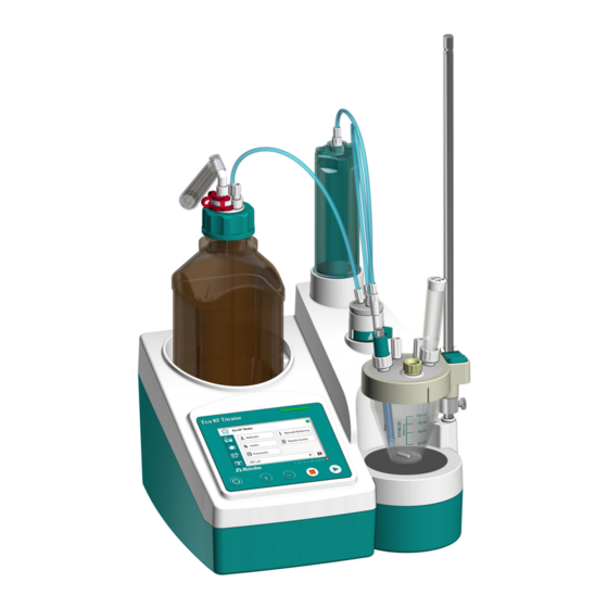
- Page 22 Eco KF Titrator – Overview ■■■■■■■■■■■■■■■■■■■■■■ Figure 5 Eco KF Titrator – Accessories Cylinder unit Tubing connections Support rod Titration cell Clamping ring Bottle unit ■■■■■■■■...
- Page 23 ■■■■■■■■■■■■■■■■■■■■■■ Functional description Figure 6 Eco KF Titrator – Peripherals Printer Q3X (opt. accessory) USB flash drive Ethernet cable (opt. accessory) Solvent Pump (opt. accessory) Power supply unit ■■■■■■■■...
-
Page 24: Dosing Unit
Eco KF Titrator – Overview ■■■■■■■■■■■■■■■■■■■■■■ 3.2.1 Dosing unit Figure 7 Dosing unit – Overview Cylinder unit Push rod (dosing drive) Flat stopcock ■■■■■■■■... - Page 25 ■■■■■■■■■■■■■■■■■■■■■■ Functional description 3.2.1.1 Cylinder unit Figure 8 Cylinder unit – Overview Light protection Dosing cylinder Piston with sealing lips and piston rod Mounting ring ■■■■■■■■...
- Page 26 Eco KF Titrator – Overview ■■■■■■■■■■■■■■■■■■■■■■ 3.2.1.2 Flat stopcock Figure 9 Flat stopcock – Overview Connector for the tubing connection to Connector for the tubing connection to the bottle the cylinder unit Connector for the tubing connection to Switching lever the buret tip ■■■■■■■■...
-
Page 27: Bottle Unit
■■■■■■■■■■■■■■■■■■■■■■ Functional description 3.2.2 Bottle unit Figure 10 Bottle unit – Overview Cannula Threaded stopper Bottle cap Amber glass bottle with GL 45 thread Clip for SGJ 14/15 Adsorber tube ■■■■■■■■... -
Page 28: Titration Cell
Eco KF Titrator – Overview ■■■■■■■■■■■■■■■■■■■■■■ 3.2.3 Titration cell Figure 11 Titration cell – Overview Adsorber tube M10 screw nipple (6.02709.010) M12 screw nipple KF titration vessel lid (6.02709.030) Titration vessel Stirring bar Septum stopper Electrode Buret tip ■■■■■■■■... -
Page 29: Function
■■■■■■■■■■■■■■■■■■■■■■ Functional description Function 3.3.1 Magnetic stirrer The magnetic stirrer ensures that the sample is well mixed. The stirring rate can be adjusted depending on the amount and viscosity of the sam- ple. 3.3.2 Dosing unit Liquid volumes can be accurately dosed with the dosing unit. The dosing unit is comprised of the following units: Cylinder unit ■... -
Page 30: Indicators And Controls
Pin assignment of the remote interface Figure 14 Pin assignment of remote socket and remote plug The above figure of the pin assignment applies to all Metrohm instru- ments with 9-pin D-Sub remote connector. Table 5 Inputs and outputs of the remote interface... - Page 31 ■■■■■■■■■■■■■■■■■■■■■■ Functional description Pin no. Assignment Function Output 0 Ready/EOD Output 1 Activate/Dosimat Output 2 Titration/Determination Output 3 Cond. OK Output 4 Error 0 volt (GND) +5 volt Input 0 Start Input 1 Stop Inputs +5 V approx. 5 kΩ Pull-up >...
-
Page 32: Remote Control
Remote control ■■■■■■■■■■■■■■■■■■■■■■ Status diagrams of the remote interface [START] [START] ready/EOD Output 0 Output 1 Titr/Determ Output 2 condOK Output 3 Error Output 4 Start Input 0 Stop Input 1 [STOP] Figure 15 Remote status diagram EOD = End of Determination Remote control The instrument can be remote controlled via an Ethernet/RS-232 connec- tion. - Page 33 ■■■■■■■■■■■■■■■■■■■■■■ Functional description Command Function Comment Hold Hold the method run. Scan instrument Acknowledgements: Ready;0, status Busy;0 or Hold;0 or Cond;0 (0 = no message). If a message on the instrument requires the interaction of the user, the acknowledgement of the status scan displays the corresponding message num- ber.
-
Page 34: Arithmetic Algorithms
Arithmetic algorithms ■■■■■■■■■■■■■■■■■■■■■■ The values of the variables are only available after the end of a determina- tion (in the status 'ready'). Acknowledge- Comment ment of the instrument Command executed Method not found Invalid variable Invalid command Arithmetic algorithms Numerical format The software of the instrument calculates in accordance with the wide- spread standard IEEE 754 (IEEE Standard for Binary Floating-Point Arith- metic for Microprocessor Systems). - Page 35 ■■■■■■■■■■■■■■■■■■■■■■ Functional description –2.38 yields –2.4 –2.45 yields –2.5 Statistics The arithmetic mean value and the absolute and relative standard devia- tions of results are calculated: You can statistically evaluate a maximum of five results (1 ≤ k ≤ 5) calcula- ted in a determination.
- Page 36 Arithmetic algorithms ■■■■■■■■■■■■■■■■■■■■■■ A complete recalculation of the statistics using a pocket calculator or PC calculation programs may exhibit deviations. This can be explained by the different binary numerical formats used by these computers. NOTICE The above losses of accuracy by rounding off in the range of signifi- cant places are only relevant theoretically.
-
Page 37: Delivery And Packaging
■■■■■■■■■■■■■■■■■■■■■■ Delivery and packaging 4 Delivery and packaging Delivery Inspect the delivery immediately upon receipt: Check the delivery against the delivery note to ensure completeness. ■ Check the product for damage. ■ If the delivery is incomplete or damaged, contact your regional Met- ■... -
Page 38: Installation
■ sockets) against moisture. If you suspect that moisture has gotten into the product, discon- ■ nect the product from the energy supply. Then notify Metrohm Service. Only personnel who have been issued Metrohm qualification may ■ perform service and repair work on electrical and electronic com- ponents. - Page 39 ■■■■■■■■■■■■■■■■■■■■■■ Installation Connecting the power cord Figure 16 Rear of the instrument – Connecting the power cord NOTICE The flat side of the plug of the power supply unit must face downwards. Connect the power supply unit to the Power IN connector. Note the orientation (see figure).
-
Page 40: Switching The Instrument On And Off
Switching the instrument on and off ■■■■■■■■■■■■■■■■■■■■■■ Switching the instrument on and off Switching on the instrument Prerequisite: The power cord is connected. ■ 1 Press the key. The instrument is initialized and a system test is performed. If the Beep parameter is activated in the system settings of the parameters, then a beep will be heard after switch-on. -
Page 41: Initial Assembly Of The Cylinder Unit
■■■■■■■■■■■■■■■■■■■■■■ Installation Initial assembly of the cylinder unit The initial assembly of the cylinder unit is carried out with an installation wizard. Scan the QR code for additional accessories. NOTICE If the instrument has already been set up, the cylinder unit is disas- sembled and assembled with the Manual control ▶... -
Page 42: Mounting The Support Rod
Mounting the support rod ■■■■■■■■■■■■■■■■■■■■■■ 3 Scan the provided QR code to watch the installation video for instal- ling the remaining accessories. NOTICE Further accessories can also be mounted without the installation wiz- ard. Mounting the support rod Mounting the support rod 1 Screw the support rod onto the stand attachment. - Page 43 ■■■■■■■■■■■■■■■■■■■■■■ Installation 3 Insert the 3 screw nipples in the M10 openings of the KF titration vessel lid. 4 Insert the 2 screw nipples in the M12 openings of the KF titration vessel lid. Equipping the volumetric KF titration cell Prerequisite: The volumetric KF titration cell is assembled.
-
Page 44: Preparing The Bottle Unit
Preparing the bottle unit ■■■■■■■■■■■■■■■■■■■■■■ 3 Push the KF titration cell down so that it is positioned approx. 1 mm above the magnetic stirrer and position it in the center of the mag- netic stirrer. To fix in place, release the green locking lever. 4 Push the clamping ring under the KF titration vessel lid. -
Page 45: Mounting The Tubing Connections
■■■■■■■■■■■■■■■■■■■■■■ Installation 2 Insert the threaded stopper. 3 Fill the adsorber tube with molecular sieve. Replacing the adsorber material (see chapter 5.9, page 39) 4 Place the filled adsorber tube on the bottle cap. 5 Secure the adsorber tube in place with the clip for SGJ 14/15. Assembling and setting up the bottle 1 Set the bottle in the bottle holder. - Page 46 Mounting the tubing connections ■■■■■■■■■■■■■■■■■■■■■■ Figure 17 Tubing connections NOTICE Tighten all the tubing connections by hand. Use no other aids. The thread of the screw nipples and the tubing openings must not be deformed. Mounting the tubing connections and the buret tip Prerequisite: Cylinder unit, titration cell and bottle unit are set up.
-
Page 47: Replacing The Adsorber Material
■■■■■■■■■■■■■■■■■■■■■■ Installation 4 Screw the buret tip securely to the 6.1805.100 tubing. NOTICE If the instrument is operated without Solvent Pump, then the M10 screw nipples for the aspiration and addition tips must be sealed tightly with the 6.02709.010 stopper. Replacing the adsorber material Replacing the adsorber material of various vessels Figure 18... - Page 48 ■ 2 Removing the adsorber material Remove the entire content. ■ This step is not necessary if the housing is empty. ■ NOTICE The molecular sieve can be regenerated at 300 °C in the drying oven, see https://www.metrohm.com/en/support-und-service/ faq-kft/. ■■■■■■■■...
- Page 49 ■■■■■■■■■■■■■■■■■■■■■■ Installation 3 Filling the housing with adsorber material Place a cotton plug loosely at the base of the housing. Do not ■ pack the cotton too tightly as sufficient gas flow has to be possi- ble. Fill the housing with molecular sieve to approx. 1 cm under the ■...
- Page 50 Replacing the adsorber material ■■■■■■■■■■■■■■■■■■■■■■ NOTICE At average humidity, we recommend replacing the adsorber material approx. every 6 weeks. An increase in drift indicates that the leak-tightness of the KF titration cell should be inspected and that the molecular sieve should possibly be replaced.
-
Page 51: Start-Up
■■■■■■■■■■■■■■■■■■■■■■ Start-up 6 Start-up Switching the instrument on and off Switching on the instrument Prerequisite: The power cord is connected. ■ 1 Press the key. The instrument is initialized and a system test is performed. If the Beep parameter is activated in the system settings of the parameters, then a beep will be heard after switch-on. -
Page 52: Setting The Language, Date And Time
Setting the language, date and time ■■■■■■■■■■■■■■■■■■■■■■ Setting the language, date and time Date, time, language and dialog type can be set once the instrument has been correctly installed. Setting the language Prerequisite: The instrument is switched on. ■ 1 On the Start page, open the System ▶ Settings menu. 2 Click on the Language button. -
Page 53: Setting The Dialog Type
■■■■■■■■■■■■■■■■■■■■■■ Start-up Setting the dialog type The user rights can be restricted with the [Dialog type] input field: Dialog type Expert (default value) ■ In the dialog type Expert, all the user settings are available. Dialog type Routine ■ In the dialog type Routine, the availability of the settings is restricted. The System and Methods menus as well as the Parameters work area can only be opened with a password. - Page 54 Setting the dialog type ■■■■■■■■■■■■■■■■■■■■■■ 2 Click in the input field. A keyboard appears. 3 Enter the password: METROHM9100 ■ Confirm with [OK]. NOTICE The password can be changed under System ▶ Change pass- wordChanging the password (see chapter 7.5.9, page 84). 4 Confirm the entry with [OK].
-
Page 55: Operation And Control
■■■■■■■■■■■■■■■■■■■■■■ Operation and control 7 Operation and control Switching the instrument on and off Switching on the instrument Prerequisite: The power cord is connected. ■ 1 Press the key. The instrument is initialized and a system test is performed. If the Beep parameter is activated in the system settings of the parameters, then a beep will be heard after switch-on. -
Page 56: User Interface
The following work areas can be selected: Eco KF Titrator start page The start page with access to the functions: Methods ■... - Page 57 ■■■■■■■■■■■■■■■■■■■■■■ Operation and control Print reports ■ Sample series ■ Sample data Access to the sample data: sample size, unit, ID1 and ID2 Parameters Access to the parameters, grouped into the following categories: Conditioning ■ Start conditions ■ Control parameters ■...
- Page 58 User interface ■■■■■■■■■■■■■■■■■■■■■■ Keyboards ■ Input of text, numbers or characters. An appropriate keyboard is called up, depending on the type of input. NOTICE Help texts Help texts (in English) are available for the input fields. The respective help text is called up by long pressing (for at least 3 seconds) on an input field.
- Page 59 ■■■■■■■■■■■■■■■■■■■■■■ Operation and control Figure 20 Display – Controls Menu path Reduce brightness Increase brightness Keyboards Different keyboard types are available. Figure 21 Keyboard (example: lower-case characters) Input field Delete entry Backspace Cancel input (close window) Apply entry Forwards in the input field Backwards in the input field Space Switch keyboard...
-
Page 60: Formula Editor
User interface ■■■■■■■■■■■■■■■■■■■■■■ Figure 22 Keyboard (example: numbers) Input field Delete entry Backspace Cancel input (close window) Apply entry Forwards in the input field Backwards in the input field Information on the input range Algebraic sign change 7.2.1 Formula editor Figure 23 Formula editor Input field... - Page 61 ■■■■■■■■■■■■■■■■■■■■■■ Operation and control formula is applied. The generally valid rules of priority apply for the calcu- lation operations. Variable Description Sample size Volume of the endpoint EP1 Sample identification (# = 1–2) Result (# = 1–5) Factor Divisor CV0# Common variable (# = 1–5) SMN# Mean value of the result R# (# = 1–5)
-
Page 62: Manual Control
Manual control ■■■■■■■■■■■■■■■■■■■■■■ Manual control The [Manual control] button on the start page offers the following func- tions: Dosing – Dose a specified volume or dose continuously. ■ Exchange cylinder unit – Empty the cylinder unit as much as possible ■... - Page 63 ■■■■■■■■■■■■■■■■■■■■■■ Operation and control 2 Configuring the dosing function NOTICE The dosing and filling rates should be decreased for viscous ■ and highly volatile liquids. The maximum dosing rate and maximum filling rate depend ■ on the cylinder volume. In manual control, the instrument doses in steps of 1/20,000 ■...
-
Page 64: Exchanging The Cylinder Unit
Manual control ■■■■■■■■■■■■■■■■■■■■■■ 2 Configuring the dosing function NOTICE The dosing and filling rates should be decreased for viscous ■ and highly volatile liquids. The maximum dosing rate and maximum filling rate depend ■ on the cylinder volume. Enter the dosing rate. ■... - Page 65 If you suspect that chemical substances have gotten into the ■ instrument, disconnect the instrument from the energy supply. Then, notify Metrohm Service. Emptying, disassembling and mounting 1 On the start page, open the Manual control menu. Click on the [Exchange cylinder unit] button.
- Page 66 Manual control ■■■■■■■■■■■■■■■■■■■■■■ The piston rises and the dosing cylinder empties as much as possible. The message Exchanging cylinder unit... appears. Once the push rod has reached the top position, the following warn- ing appears: Make sure that the tubing from the bottle cap is removed. ■...
-
Page 67: Preparing The Buret (Prep)
■■■■■■■■■■■■■■■■■■■■■■ Operation and control Carefully push the cylinder unit downwards. The piston is pushed ■ into the dosing cylinder. Screw the light protection of the cylinder unit securely into the thread of the housing. 6 Click on the [Continue] button. The push rod moves the piston into the basic position. -
Page 68: Operating The Magnetic Stirrer
Manual control ■■■■■■■■■■■■■■■■■■■■■■ 3 Make sure that the buret tip points into a vessel. [Continue] The piston rises and sinks and the cylinder empties and fills in 2 cycles. Then, the buret is prepared. 7.3.4 Operating the magnetic stirrer Switching the stirrer on and off 1 Add the stirring bar to the titration vessel. -
Page 69: Methods
■■■■■■■■■■■■■■■■■■■■■■ Operation and control Stirring rate The stirring rate can be adjusted in 15 steps. The default value is 8. Setting the stirring rate Prerequisite: The magnetic stirrer controls are opened: Start page ▶ Manual con- ■ trol ▶ Stirrer The stirrer is switched on. - Page 70 Methods ■■■■■■■■■■■■■■■■■■■■■■ Figure 24 Method selection bar Display in the Example Meaning method selection Method name KFT_Ipol The method is saved in the method list. Method name KFT_Ipol The method has just been created. [New] [New] It has not been saved. Method name KFT_Ipol The method has been modified.
-
Page 71: Using And Managing Methods
■■■■■■■■■■■■■■■■■■■■■■ Operation and control Figure 25 Method list (example) A scroll bar appears if the list is longer. Titration mode Each method is based on the same titration mode. The following titration modes are available: KFT Ipol – Method for the content determination of water in the sam- ■... - Page 72 Methods ■■■■■■■■■■■■■■■■■■■■■■ Export method – Print out the method or save it to a USB flash drive. ■ Import method – Add a method from a USB flash drive to the ■ method list. Loading the method 1 Open the method selection bar on the Start page: Click on A list with the saved methods appears.
- Page 73 ■■■■■■■■■■■■■■■■■■■■■■ Operation and control 2 Click on the input field. A keyboard appears. 3 Enter the desired name with the keyboard. Finish with [OK]. The name that was entered appears in the method selection bar. The method is now saved in the method list. Creating a new method 1 On the Start page, click on the [Methods] button.
- Page 74 Methods ■■■■■■■■■■■■■■■■■■■■■■ NOTICE If modifications on the method that was loaded before have not been saved, the following warning appears: Store method: The modifications of the current method have not been saved. Do you want to load the method anyway? [Yes] –...
- Page 75 ■■■■■■■■■■■■■■■■■■■■■■ Operation and control 4 Confirm deleting: [Delete] The deleted method is no longer available in the method list. Exporting a method 1 Connect the USB flash drive to the instrument. 2 On the Start page, click on the [Methods] button. The method list appears.
- Page 76 Methods ■■■■■■■■■■■■■■■■■■■■■■ 2 On the Start page, click on the [System] button. Move to page 2 and click on [File management]. A list with the methods saved on the USB flash drive appears. 3 Select the method that you want to import by clicking on it. The selected method is highlighted in green.
-
Page 77: System - Configuration
■■■■■■■■■■■■■■■■■■■■■■ Operation and control System – Configuration The system configuration of the Eco KF Titrator defines the basic, method- independent configuration of the instrument. The following submenus can be found under the [System] button on the Start page: Settings – Basic instrument settings. -
Page 78: System - Settings
System – Configuration ■■■■■■■■■■■■■■■■■■■■■■ Change password ■ COM port settings ■ 7.5.1 System – Settings System ▶ Settings Figure 26 System – Settings page 1 Figure 27 System – Settings page 2 User name A user name can be entered for the report. This parameter will only be printed if a user has been defined. - Page 79 ■■■■■■■■■■■■■■■■■■■■■■ Operation and control Instrument name An instrument name can be entered for the report. This parameter will only be printed if a designation has been defined. Input: max. 10 characters Default value: empty Language Set the dialog language. Dialog type The user dialog can be limited for routine operations.
- Page 80 System – Configuration ■■■■■■■■■■■■■■■■■■■■■■ Date Current date. Only numbers that make sense can be entered. Format: YYYY:MM:DD PREP warning If the PREP warning is activated, the recommendation to execute the Prepare buret (PREP) function appears: After the instrument is switched on. ■...
-
Page 81: Managing Solutions
■■■■■■■■■■■■■■■■■■■■■■ Operation and control 7.5.2 Managing solutions System ▶ Solutions Figure 28 Solution list (example) Table 6 Managing the solution list Add a new solution to the list. Solution data see below. Edit the data of the selected solution. Solution data see below. - Page 82 System – Configuration ■■■■■■■■■■■■■■■■■■■■■■ Figure 29 Solutions – Solution data page 1 Figure 30 Solutions – Solution data page 2 Name The designation of the solution is used for unique identification. Input: max. 24 characters Default value: empty Titer Titer of the solution. Input range –999,999,999 to 9,999,999,999 Default value...
- Page 83 ■■■■■■■■■■■■■■■■■■■■■■ Operation and control Selection: µmol/mL ■ mmol/L ■ mol/L ■ ■ mg/L ■ mg/mL ■ µg/L ■ ■ ■ mEq/L ■ empty ■ User-defined ■ A user-defined unit can be created. This will be added to the selection list. The previous entry will be overwritten as soon as the new unit has been defined.
-
Page 84: Managing Common Variables
System – Configuration ■■■■■■■■■■■■■■■■■■■■■■ When you start a method, you will be notified if this time interval (in days) has already elapsed. You can then select whether or not you would still like to start the method. 1 to 999 d Input range 999 d Default value... -
Page 85: Managing External Devices
■■■■■■■■■■■■■■■■■■■■■■ Operation and control Assigning a result automatically to a common variable 1 Loading the method Load the method that contains the result to be used in the ■ method selection bar on the Start page. 2 Opening the editing dialog of the result Open the Parameters work area. - Page 86 System – Configuration ■■■■■■■■■■■■■■■■■■■■■■ Selection: USB flash drive ■ Ethernet/RS-232 ■ Default value: USB flash drive USB flash The report is saved as a TXT file on the USB flash drive in drive the folder pc_lims_report. Ethernet/ The report is sent via an RS-232 instrument server. The RS-232 interface parameters are set on the RS-232 instrument server (see Application Bulletin AB-435).
-
Page 87: System - File Management
■■■■■■■■■■■■■■■■■■■■■■ Operation and control 7.5.5 System – File management System ▶ File management This dialog offers the following functions: Importing a method from a USB flash drive to the instrument. ■ Deleting the method on the USB flash drive. ■ Writing a system backup to a USB flash drive. - Page 88 System – Configuration ■■■■■■■■■■■■■■■■■■■■■■ 3 Select the method that you want to import by clicking on it. The selected method is highlighted in green. 4 Import the highlighted method: The message Importing method from USB flash drive... appears. Once the message has disappeared, the method is saved to the instrument.
- Page 89 ■■■■■■■■■■■■■■■■■■■■■■ Operation and control 3 Select the method that you want to delete by clicking on it. The selected method is highlighted in green. 4 Delete the highlighted method: The message Method deleted successfully from USB flash drive. confirms the deletion process. Creating a backup 1 Connect the USB flash drive to the instrument.
-
Page 90: Instrument Diagnosis
System – Configuration ■■■■■■■■■■■■■■■■■■■■■■ 3 Restore the system: A list with the backups saved on the USB flash drive appears. The file names of the backups are structured as follows: SF_YYYY- MM-DD_hhmmss.ods 4 Click on the desired backup. The warning System restore appears. 5 Confirm the system restore: [Yes] The following message appears before the instrument is restarted: System files are restored. -
Page 91: Ethernet Settings
■■■■■■■■■■■■■■■■■■■■■■ Operation and control Display test The [Display test] button offers settings for brightness, various test images and a calibration program for the screen: Brightness Set the screen brightness: buttons Shows a number of test images to check image quality. Starts the calibration program. -
Page 92: Service - Brief Description
System – Configuration ■■■■■■■■■■■■■■■■■■■■■■ 7.5.8 Service – Brief description The [Service] button leads to a protected area to which only Metrohm Service has access. 7.5.9 Changing the password With the password for the Expert dialog type, you can control access to the menus System and Methods as well as the Parameters work area. - Page 93 ■■■■■■■■■■■■■■■■■■■■■■ Operation and control Selection: 1,200 ■ 2,400 ■ 4,800 ■ 9,600 ■ 19,200 ■ 38,400 ■ 57,600 ■ 115,200 ■ Default value: 9,600 Data bits Number of data bits. Selection: ■ ■ Default value: 8 Stop bits Number of stop bits. Selection: ■...
-
Page 94: Carrying Out The Determination
Carrying out the determination ■■■■■■■■■■■■■■■■■■■■■■ Selection: Hardware ■ Software ■ none ■ Default value: Hardware NOTICE If communication problems occur, set the parameter Handshake to Software, and make another attempt. Carrying out the determination 1 Loading the method Load the desired method. ■... - Page 95 ■■■■■■■■■■■■■■■■■■■■■■ Operation and control Figure 33 Live status The axes are scaled automatically. Pauses the determination. Continues the determination. This button appears as soon as the determination is paused. 6 Making live modifications (if necessary) Edit the sample data of the running determination ■...
- Page 96 Carrying out the determination ■■■■■■■■■■■■■■■■■■■■■■ 2 Editing the sample data Edit the sample data. ■ 3 Opening the Live status work area Click on ■ The Live status work area appears again. NOTICE If the determination is finished while an editing dialog is opened (e.g. of the sample size), then this will be closed automatically and the results dialog will be displayed.
-
Page 97: Results
■■■■■■■■■■■■■■■■■■■■■■ Operation and control Modifying the stirring rate while a determination is run- ning 1 The stirring rate of the magnetic stirrer can be changed with the con- trol bar while a determination is carried out. Increase the stirring rate in steps: ■... - Page 98 Results ■■■■■■■■■■■■■■■■■■■■■■ Recalculating By clicking on the key, the current determination is recalculated. The procedure will be executed immediately. NOTICE Recalculation cannot be undone. All the results of the determination that was carried out last are recalcula- ted with the Recalc function. This is necessary if, for example, the calcula- tion, the titer or the sample size has been modified.
- Page 99 ■■■■■■■■■■■■■■■■■■■■■■ Operation and control The mean value Mean, the absolute standard deviation s abs and the rel- ative standard deviation s rel are displayed in the overview. For the mean value, the number of individual results from which it has been calculated is displayed in parentheses.
-
Page 100: Printing Reports
Printing reports ■■■■■■■■■■■■■■■■■■■■■■ Printing reports The following reports can be printed out: Results Result report with determination properties, sample data, calculated results, etc. Parameter Report with all method parameters of the loaded method. System System report with system settings, solution list, external devices, etc. Preparing to print 1 On the start page, open System ▶... -
Page 101: Parameters
■■■■■■■■■■■■■■■■■■■■■■ Operation and control Parameters Figure 35 Parameters – Menu page 1 Figure 36 Parameters – Menu page 2 7.9.1 Conditioning Parameters ▶ Conditioning The conditions required for conditioning are defined under [Condition- ing]. Conditioning If this parameter is activated, the first time the titration is started the work- ing medium will be titrated to the endpoint with the specified control parameters. - Page 102 Parameters ■■■■■■■■■■■■■■■■■■■■■■ Selection: ■ ■ Default value: ON Start drift Conditioning OK will be displayed as soon as the value falls below this volume drift and the titration can be started. Input range 1 to 999 μL/min Default value 20 μL/min Drift correction The endpoint volume can be corrected for drift.
-
Page 103: Start Conditions
■■■■■■■■■■■■■■■■■■■■■■ Operation and control ing is continued by pressing [START] once again, then the titrant volume that has already been dosed will not be taken into account; i.e. the dosing starts again at zero. The stop volume should be adjusted to the size of the titration cell in order to prevent any overflow. - Page 104 Parameters ■■■■■■■■■■■■■■■■■■■■■■ Input range 0.01 to 166.00 mL/min Default value Max. mL/min Additional selection: Max. = maximum dosing rate. Default value: Max. NOTICE The maximum dosing rate depends on the cylinder volume (see table). If volatile solvents/solutions or solutions with a high viscosity are used, the dosing rate must be reduced accordingly so that the cylin- der unit is not overloaded.
-
Page 105: Titration Parameters
■■■■■■■■■■■■■■■■■■■■■■ Operation and control Switch: ■ ■ Default value: OFF Request sample unit If this parameter is activated, then the unit for the sample size will be requested at the start of the determination. Switch: ■ ■ Default value: OFF Hold at request If this parameter is activated, then the run will be paused during the request. - Page 106 Parameters ■■■■■■■■■■■■■■■■■■■■■■ I(pol) The polarization current is the current that is applied to a polarizable elec- trode during voltametric measurement. Selection: ■ ■ ■ ■ Default value: 50 μA Electrode test In the case of polarizable electrodes, an electrode test can be carried out. A check is made that the electrode is properly connected and that no short-circuit is present.
-
Page 107: Control Parameters
■■■■■■■■■■■■■■■■■■■■■■ Operation and control the rotational speed is specified in Stirring rate (see "Setting the stirring rate", page 61). The optimum stirring rate can be tested in the manual control. 1 to 15 Input range Default value Extraction time Minimum duration of the titration. The titration will not be canceled dur- ing the extraction time, even if the endpoint has already been reached. - Page 108 Parameters ■■■■■■■■■■■■■■■■■■■■■■ Fast For uncritical samples with high water content. User The individual titration parameters can be modified. The settings of the individual titration rates are listed below. Table 8 Default values of the predefined titration rates for KFT Titration rate slow optimal fast...
- Page 109 ■■■■■■■■■■■■■■■■■■■■■■ Operation and control NOTICE The maximum dosing rate depends on the cylinder volume (see table). If volatile solvents/solutions or solutions with a high viscosity are used, the dosing rate must be reduced accordingly so that the cylin- der unit is not overloaded. Table 9 Maximum dosing rate / filling rate Cylinder volume...
- Page 110 Parameters ■■■■■■■■■■■■■■■■■■■■■■ page 103) always lead to a stop, even if the stop criterion has not been reached. Selection: Drift ■ Time ■ Rel. drift ■ ■ Default value: Drift Drift The titration is canceled if the value falls below both the endpoint and the stop drift.
-
Page 111: Stop Conditions
■■■■■■■■■■■■■■■■■■■■■■ Operation and control Input range 1 to 999 μL/min Default value 10 μL/min 7.9.5 Stop conditions Parameters ▶ Stop conditions The conditions for canceling the titration are defined under [Stop condi- tions], if this does not occur automatically. This could be the case if the endpoint set is not reached or if the stop criterion is not fulfilled. -
Page 112: Calculation - Blank Ipol Methods
Parameters ■■■■■■■■■■■■■■■■■■■■■■ Cylinder volume maximum dosing rate / filling rate 5 mL 15.00 mL/min 10 mL 30.00 mL/min 20 mL 60.00 mL/min 50 mL 150.00 mL/min 7.9.6 Calculation – Blank Ipol methods Parameters ▶ Calculation Calculation formula EP1*FCT The calculated result is saved for each measuring mode separately as vari- able Blank value (CV01). - Page 113 ■■■■■■■■■■■■■■■■■■■■■■ Operation and control Depending on what you use to determine the titer of the reagent and which unit the sample size has, the Factor (FCT) parameter has to be adjusted. Table 11 Conversion table Used standard Sample size Factor (FCT) in …...
-
Page 114: Calculation - Kft Ipol Method
Parameters ■■■■■■■■■■■■■■■■■■■■■■ A user-defined unit can be created. This will be added to the selection list. As soon as a new unit is defined, the previous entry will be overwritten. An empty entry can be generated this way as well. 7.9.8 Calculation –... -
Page 115: Calculation - Kft Ipol-Blank Method
■■■■■■■■■■■■■■■■■■■■■■ Operation and control Titer Titer of the solution used. If a solution is selected in Titration parame- ters, the value and unit from the solution data in System ▶ Solutions is read out and displayed here. If the titer is manually changed here, the sol- ution data is updated. - Page 116 Parameters ■■■■■■■■■■■■■■■■■■■■■■ Result unit Sample size Factor (FCT) Divisor (DIV) in … Density of the sample in g/mL 1,000 1,000 Density of the sample in g/mL mg/mL Density of the sample in g/mL mg/mL mg/piece Pieces Factor (FCT) Conversion factor, see table above. Input range –999,999,999 to 9,999,999,999 Default value...
-
Page 117: Statistics
■■■■■■■■■■■■■■■■■■■■■■ Operation and control Decimal places Number of decimal places used to display the result. Input range 0 to 5 Default value Result unit The result unit is displayed and saved along with the result. Selection: ■ ■ mg/mL ■ ■... -
Page 118: Reports
Reports ■■■■■■■■■■■■■■■■■■■■■■ If an additional determination has to be added to the determination ser- ies, because one determination has been incorrect, for example, then this can be accomplished in the statistical overview . 2 to 20 Input range Default value 7.11 Reports Parameters ▶... - Page 119 ■■■■■■■■■■■■■■■■■■■■■■ Operation and control Measuring point list Output of the measuring point list. Selection: ■ ■ Default value: OFF Parameters All of the parameters of the current method are printed out in the param- eter report. Selection: ■ ■ Default value: OFF PC/LIMS The PC/LIMS report is a machine-readable report with all of the important data for a determination.
-
Page 120: Maintenance
Metrohm recommends having the products maintained by specialist ■ personnel of Metrohm AG as part of an annual service. Shorter mainte- nance intervals may be necessary if you frequently work with caustic and corrosive chemicals. -
Page 121: Performing Maintenance On The Cylinder Unit
Protect live components (e.g. power supply unit, power cord, con- ■ nection sockets) against moisture. Always have maintenance work and repairs on electrical compo- ■ nents carried out by a regional Metrohm service representative. Prerequisite: The product is switched off and disconnected from the energy supply. ■ Required accessories: Cleaning cloth (soft, lint-free) ■... - Page 122 If you suspect that chemical substances have gotten into the ■ instrument, disconnect the instrument from the energy supply. Then, notify Metrohm Service. Maintenance steps Emptying the cylinder unit as far as possible and removing it ■...
- Page 123 ■■■■■■■■■■■■■■■■■■■■■■ Maintenance NOTICE It is normally not necessary to remove the mounting ring out of the light protection or the screw nipple on the dosing cylinder for clean- ing. The parts can be cleaned while still in their pre-mounted state. Push the dosing cylinder out of the light protection from above.
- Page 124 Cleaning the product surface ■■■■■■■■■■■■■■■■■■■■■■ Are scratches visible on the piston surface? ■ Is any unevenness visible on the sealing lips of the piston? ■ If any of these defects is visible, replace the entire cylinder unit. Assembling the cylinder unit Required accessories: 6.2803.010 paraffin grease ■...
-
Page 125: Mounting The Cylinder Unit
■■■■■■■■■■■■■■■■■■■■■■ Maintenance 8.2.2 Mounting the cylinder unit For mounting the cylinder unit see the following chapter Exchanging the cylinder unit (see chapter 7.3.2, page 56) Displaying system data The System ▶ About menu path shows detailed information on: Program version ■... - Page 126 Resetting the system ■■■■■■■■■■■■■■■■■■■■■■ Resetting the system Prerequisite: The instrument is switched off. ■ 1 Switching on the instrument Press the key. 2 Resetting the system Wait until the following text is displayed in the bottom line of the screen: Initializing, please wait...
-
Page 127: Disposal
■■■■■■■■■■■■■■■■■■■■■■ Disposal 9 Disposal Properly dispose of chemicals and of the product to reduce negative effects on the environment and public health. Local authorities, waste dis- posal companies or dealers provide more detailed information on disposal. Observe the WEEE EU directive (WEEE = Waste Electrical and Electronic Equipment) for the proper disposal of waste electronic equipment within the European Union. -
Page 128: 10 Technical Specifications
Ambient conditions ■■■■■■■■■■■■■■■■■■■■■■ 10 Technical specifications 10.1 Ambient conditions Nominal function range +5 to +45 °C max. 80% relative humidity, non- condensing Storage +5 to +45 °C 10.2 Energy supply External power supply unit Input Nominal voltage range 100–240 VAC Frequency range 50–60 Hz Current... -
Page 129: Dimensions
■■■■■■■■■■■■■■■■■■■■■■ Technical specifications Current at the power supply unit 500 mA max. output current per channel Protection Internal fuse 1.5 A 10.3 Dimensions Measurements Width 286 mm Height without cylinder unit 220 mm with cylinder unit 358 mm with support rod 508 mm Depth 286 mm... -
Page 130: Connectors Specifications
D-Sub 9-pin Ethernet CAT 6 Type Socket RJ-45 Cable type min. FFTP shielded Cable length max. 10 m from Metrohm acces- sories Type Socket type A Cable type shielded Cable length max. 5 m from Metrohm acces- sories Measuring inputs... -
Page 131: Display Specifications
■■■■■■■■■■■■■■■■■■■■■■ Technical specifications 10.6 Display specifications Display Type VGA color display Size approx. 4.3" diagonal Resolution 480 × 272 pixels Status display green 10.7 Operation specifications Touch panel Type resistive Resistance to chemicals resistant to the following chemicals (no visible changes after 24 h of dura- tion of action): ethanol... -
Page 132: Stirrer Specifications
Stirrer specifications ■■■■■■■■■■■■■■■■■■■■■■ Measuring accuracy applies to all measuring ranges without sensor error, under reference conditions, measuring interval 100 ms, ambient temperature +25 °C (± 3 °C), relative humidity ≤ 60% 10.9 Stirrer specifications Variant magnetic Adjustment range for rotational +1 to +15 120–1,800 rpm speed...
Need help?
Do you have a question about the Eco KF Titrator and is the answer not in the manual?
Questions and answers