Table of Contents
Advertisement
Quick Links
73M1903 MODEM ANALOG FRONT END DEMO BOARD User's Manual
TERIDIAN 73M1903
Modem Analog Front End
Demo Board
USER'S MANUAL
July 15, 2005
Version 1.2
TERIDIAN Semiconductor Corporation
6440 Oak Canyon Rd.
Irvine, CA 92618-5201
Ph: 714-508-8800 ▪ Fax: (714) 508-8878
http://www.teridiansemi.com/
Revision 1.2
1 of 32
© Copyright 2005 TERIDIAN Semiconductor Corporation
Advertisement
Table of Contents

Related Manuals for Teridian 73M1903


Summary of Contents for Teridian 73M1903
- Page 1 73M1903 MODEM ANALOG FRONT END DEMO BOARD User’s Manual TERIDIAN 73M1903 Modem Analog Front End Demo Board USER’S MANUAL July 15, 2005 Version 1.2 TERIDIAN Semiconductor Corporation 6440 Oak Canyon Rd. Irvine, CA 92618-5201 Ph: 714-508-8800 ▪ Fax: (714) 508-8878 http://www.teridiansemi.com/...
- Page 2 73M1903 MODEM ANALOG FRONT END DEMO BOARD User’s Manual TERIDIAN Semiconductor Corporation makes no warranty for the use of its products, other than expressly contained in the Company’s warranty detailed in the TERIDIAN Semiconductor Corporation standard Terms and Conditions. The company assumes no responsibility for any errors which may appear in this document, reserves the right to change devices or specifications detailed herein at any time without notice and does not make any commitment to update the information contained herein.
- Page 3 73M1903 MODEM ANALOG FRONT END DEMO BOARD User’s Manual 73M1903 MODEM ANALOG FRONT END IC DEMO BOARD USER’S MANUAL July 15, 2005 Revision 1.2 Revision 1.2 3 of 32 © Copyright 2005 TERIDIAN Semiconductor Corporation...
-
Page 4: Table Of Contents
73M1903 MODEM ANALOG FRONT END DEMO BOARD User’s Manual Table of Contents GETTING STARTED ............................7 General................................7 Safety and ESD Notes............................. 7 DEMO BOARD LOOK ............................7 SYSTEM DESCRIPTION ..........................11 MAFE INTERFACE............................11 73M1903 Register map..........................13 73M1903 system initialization ........................14 HARDWARE DESCRIPTION.......................... - Page 5 List of Figures Figure 1-1: 73M1903 Demo Board..........................8 Figure 1-2: TERIDIAN 73M1903 Demo Board connected to a Host System ..............8 Figure 1-3: Block diagram for the TERIDIAN 73M1903 Demo Board ................9 Figure 2-1: 73M1903 MAFE Interface signals......................11 Figure 2-2: MAFE Timing diagram ..........................
- Page 6 73M1903 MODEM ANALOG FRONT END DEMO BOARD User’s Manual This page was intentionally left blank. Revision 1.2 6 of 32 © Copyright 2005 TERIDIAN Semiconductor Corporation...
-
Page 7: Getting Started
The TERIDIAN Semiconductor Corp. (TSC) 73M1903 Demo Board is a Modem Analog Front End demonstration board with on board DAA for evaluating the 73M1903 device that can support up to V.90/V.92 modulation and demodulation on high-performance DSP or CPU systems available in the market. -
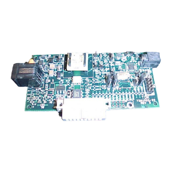
Page 8: Figure 1-1: 73M1903 Demo Board
73M1903 MODEM ANALOG FRONT END DEMO BOARD User’s Manual Figure 1-1: 73M1903 Demo Board Figure 1-2: TERIDIAN 73M1903 Demo Board connected to a Host System Revision 1.2 8 of 32 © Copyright 2005 TERIDIAN Semiconductor Corporation... -
Page 9: Figure 1-3: Block Diagram For The Teridian 73M1903 Demo Board
73M1903 Evaluation board SCLK TXAP TXAN RXAP SDIN RXAN SDOUT PHONE 73M1903 Line GPIO5(OH) RESET GPIO4(RING) XTAL POWER RING SUPPLY Figure 1-3: Block diagram for the TERIDIAN 73M1903 Demo Board Revision 1.2 9 of 32 © Copyright 2005 TERIDIAN Semiconductor Corporation... - Page 10 73M1903 MODEM ANALOG FRONT END DEMO BOARD User’s Manual This page was intentionally left blank. Revision 1.2 10 of 32 © Copyright 2005 TERIDIAN Semiconductor Corporation...
-
Page 11: System Description
2 SYSTEM DESCRIPTION 2.1 MAFE INTERFACE The Modem Analog Front End (MAFE) Interface is a serial port integrated into the TERIDIAN TERIDIAN73M1903 device to interface to a host processor or a DSP. This serial data port is a bi- directional port that can be supported by most DSPs with a synchronous serial port or GPIO that can be configured as a serial port. -
Page 12: Figure 2-2: Mafe Timing Diagram
73M1903 MODEM ANALOG FRONT END DEMO BOARD User’s Manual SCLK SDIN TX15 TX14 TX13 TX12 TX11 TX10 TX9 TX8 TX7 TX6 TX5 TX4 TX3 TX2 TX1 TX0 SDOUT RX15 RX14 RX13 RX12 RX11 RX10 RX9 RX8 RX7 RX6 RX5 RX4 RX3 RX2 RX1 RX0... -
Page 13: 73M1903 Register Map
2.2 73M1903 REGISTER MAP The following table shows the memory map of addressable registers in the 73M1903. Each register and bits can be read or written by a host processor or a DSP using the control frames over the MAFE interface. -
Page 14: 73M1903 System Initialization
73M1903 MODEM ANALOG FRONT END DEMO BOARD User’s Manual 2.3 73M1903 SYSTEM INITIALIZATION The following example shows the sequence to bring the 73M1903 device out of reset and to start up after power up. NOTE: The TERIDIAN73M1903 device does not have an automatic power on reset circuit. After the power has stabilized, a reset signal should be asserted from the host by pulling the reset pin low for 100ns or longer. - Page 15 73M1903 MODEM ANALOG FRONT END DEMO BOARD User’s Manual CTRL_FRAME, CTRL13|AFE_CTRL13 Example 2. Using Automatic control Frame (Hardware controlled control frame): static const U16 init_afe_config[] = // MUST HAVE Dummy Data, Control, Dummy Data….. FRAMES CTRL2|0x00, CTRL2|0x00, // Force to Software controlled control frame...
- Page 16 73M1903 MODEM ANALOG FRONT END DEMO BOARD User’s Manual This page was intentionally left blank. Revision 1.2 16 of 32 © Copyright 2005 TERIDIAN Semiconductor Corporation...
-
Page 17: Hardware Description
3 HARDWARE DESCRIPTION 3.1 BOARD SETTING: JUMPERS AND CONNECTORS Figure 3-1 shows the connectors and jumpers available on 73M1903 Demo Boards. JS1 is the main connector for communicating with a host processor or DSP board. The pins of this interface connector are configurable by 0 Ohm resistors. -
Page 18: Table 3-1: 73M1903 Demo Board Connectors
Ring detector Three-pin header that allows selection of the Ring detector output output to connect to either GPIO4 of 73M1903 or to a Host CPU GPIO through JS1 or JP25. 1-2: Ring detector output is fed to 73M1903 GPIO4. (73M1903 GPIO4 must be configured as an input.) -
Page 19: Table 3-3: 73M1903 Demo Board Jumper Settings
JS1 can be to be used in applications where the 73M1903 demo board is plugged directly into a target application or adaptor board. It also allows flexibility in the assignment of the signals to the connector. If a ribbon cable connection is preferred, JP2 can be used instead. -
Page 20: Board Hardware Specifications
73M1903 MODEM ANALOG FRONT END DEMO BOARD User’s Manual 3.2 BOARD HARDWARE SPECIFICATIONS 4.00 0.20 0.15 0.27 0.69 0.35 TRANS 2.00 0.62 RJ11 20P CONN 0.33 1.17 1.18 Figure 3-2: PCB Dimensions PCB Dimensions • Size 4.00x2.00” • Height w/ components and solder 0.61”... -
Page 21: Appendix
73M1903 MODEM ANALOG FRONT END DEMO BOARD User’s Manual 4 APPENDIX This appendix includes the following documentation, tables and drawings: Examples of typical sample rate selection 73M1903 Demo Board schematic diagrams 73M1903 Demo Board Bills of Materials 73M1903 PC board layout 73M1903 Pin-out 4.1 EXAMPLE OF TYPICAL SAMPLE RATE SETTINGS... -
Page 22: Demo Board Schematic Diagram
4.2 DEMO BOARD SCHEMATIC DIAGRAM There are few variations of 73M1903 Demo boards available. One of them is the Low cost minimum feature US DAA design. And another one is the full-featured CTR21 compliant DAA design with parallel phone pickup detection circuit. And the other is a US High speed DAA design. These schematics are shown here. -
Page 23: Figure 4-2: Schematic Diagram Of Us High Speed Daa
73M1903 DEMO BOARD User’s Manual LIUCK RINGD HOOK SCLK AFEIN AFEOUT RESET HEADER 5X2 VCCD 0.047uF 0.1uF 3.3uF FZT605CT RXAN MMST2222A-7 4.7K C8 NC 73M1903-TQFP TXAN TRAN1 TP13 73M1903-32QFN Sumida C1 3.3uF RESET MIT4033 VCCA .082UF 1/4W + C15 SDOUT SDOUT 0.15uF... -
Page 24: Figure 4-3: Schematic Diagram Of Ctr21 Daa
---Caller ID U.S.DAA (LDA111) Title ---PPU-E and PPU-V JS 1 - RW5 Connector 20 pin Rt. angle socket 73M1903 32 QFN CTR-21 P Demo Board Install R27, 33, 37, 40, 44, 45, 46, 47 ---LIU-E and LIU-V power connector Size... -
Page 25: Demo Board Bills Of Materials
73M1903 DEMO BOARD User’s Manual 4.3 DEMO BOARD BILLS OF MATERIALS Table 4-2:US Low Speed Bill of Materials Item Quantity Reference Part C1,C2 0 Ohms C6,C9 3.3uF C3,C5,C18 0.15uF .082UF 10uF C10,C11,C12,C13,C21 0.1uF 33pF C17,C19 0.47uF 22pF BZT52C16S D5,D6 BZT52C22S... -
Page 26: Table 4-3: Us High Speed Bill Of Materials
73M1903 DEMO BOARD User’s Manual Table 4-3: US high speed Bill of Materials Item Quantity Reference Part C1,C2,C6,C9 3.3uF C3,C5 0.15uF 0.15uF, 250V .082UF C7,C15 10uF C10,C11,C12,C13,C21 0.1uF 33pF C17,C19 0.47uF, 250V 22pF 0.047uF BZT52C16S D5,D6 BZT52C22S TB3100H MF-R015/600 JP1,JP3... -
Page 27: Table 4-4: Ctr 21 Bill Of Materials
73M1903 DEMO BOARD User’s Manual Table 4-4: CTR 21 Bill of Materials Item Quantity Reference Part C1,C2,C6,C9 3.3uF C3,C5 0.15uF 0.15uF, 250V .082UF C7,C15 10uF C8,C22 300pF C10,C11,C12,C13,C21 0.1uF 33pF C17,C19 0.47uF, 250V 22pF BZT52C16S D2,D7 BZT52C12S D5,D6 BZT52C22S TB3100H... -
Page 28: Demo Board Pcb Layout
73M1903 DEMO BOARD User’s Manual 4.4 DEMO BOARD PCB LAYOUT Figure 4-4:TERIDIAN 73M1903 DEMO BOARD: Silk Screen Top Figure 4-5: TERIDIAN 73M1903 DEMO BOARD: Top Signal Layer Revision 1.2 28 of 32 © Copyright 2005 TERIDIAN Semiconductor Corporation... -
Page 29: Figure 4-6: Teridian 73M1903 Demo Board: Bottom Signal Layer
73M1903 DEMO BOARD User’s Manual Figure 4-6: TERIDIAN 73M1903 DEMO BOARD: Bottom Signal Layer Figure 4-7: TERIDIAN 73M1903 DEMO BOARD: Supply Plane Revision 1.2 29 of 32 © Copyright 2005 TERIDIAN Semiconductor Corporation... -
Page 30: Figure 4-8: Teridian 73M1903 Demo Board: Ground Plane
73M1903 DEMO BOARD User’s Manual Figure 4-8: TERIDIAN 73M1903 DEMO BOARD: Ground Plane Revision 1.2 30 of 32 © Copyright 2005 TERIDIAN Semiconductor Corporation... -
Page 31: 73M1903 Pin Description
73M1903 DEMO BOARD User’s Manual 4.5 73M1903 PIN DESCRIPTION Table 4-4: 73M1903 Pin Description PIN NAME TYPE PIN # DESCRIPTION 1,22 Negative Digital Ground Negative Analog Ground 2,25 Positive Digital Supply Positive Analog Supply VPPLL Positive PLL Supply, shared with VPD... - Page 32 Figure 4-17: TERIDIAN 73M1903 TQFP/QFN-32: Pin-out (top view) User Manual: This User Manual contains proprietary product definition information of TERIDIAN Semiconductor Corporation (TSC) and is made available for informational purposes only. TERIDIAN assumes no obligation regarding future manufacture, unless agreed to in writing.
Need help?
Do you have a question about the 73M1903 and is the answer not in the manual?
Questions and answers