Table of Contents
Advertisement
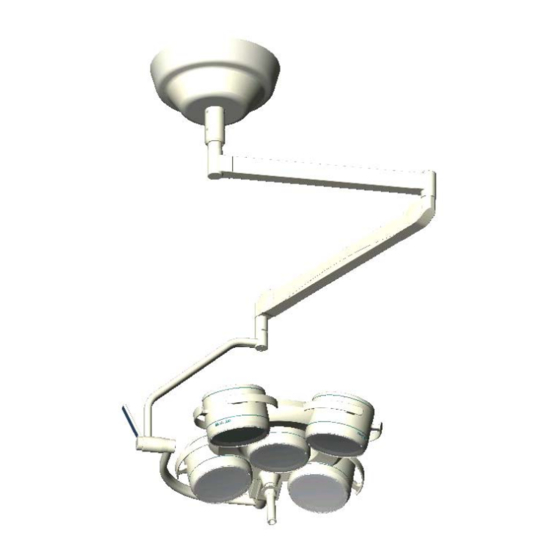
Ceiling and wall attachment
C
e
i
l
i
n
C
e
i
l
i
n
Dr. Mach
59500001
M
O
U
N
T
I
N
G
M
O
U
N
T
I
N
G
g
a
t
t
a
c
h
m
g
a
t
t
a
c
h
m
Applies to:
GmbH u. Co., Flossmannstrasse 28, D-85560 Ebersberg
Tel.: +49 (0)8092 2093 0, Fax +49 (0)8092 2093 50
Internet: www.dr-mach.com, E-mail:
Edition 06
I
N
S
T
R
U
C
T
I
I
N
S
T
R
U
C
T
I
e
n
t
W
a
l
l
a
e
n
t
W
a
l
l
a
Soloflex
Triaflex
Trigenflex
Quintaflex
Mach 120
Mach 130
Mach M3
Mach M5
Mach 380
Mach 400
Mach 500
Tool and instrument trays
info@dr-mach.de
Dr. Mach
Lamps and Engineering
O
N
S
O
N
S
t
t
a
c
h
m
e
n
t
t
t
a
c
h
m
e
n
t
11.03.2003 / Bak Page 1/48
Advertisement
Table of Contents


Need help?
Do you have a question about the Soloflex and is the answer not in the manual?
Questions and answers