
Related Manuals for Eaton Cutler-Hammer FD100


Summary of Contents for Eaton Cutler-Hammer FD100
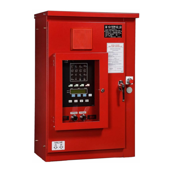
- Page 1 Diesel Engine Fire Pump Controllers Instructions IM05805016K For more information visit: www.chfire.com...
- Page 3 IM05805016K Page i Table of Contents INSTALLATION AND MOUNTING ........................1 ELECTRICAL CONNECTIONS ........................1 WIRE SIZES ..............................1 SYSTEM PRESSURE CONNECTION ......................2 MAIN DISPLAY PANEL ............................2 LCD DISPLAY ...............................2 ANNUNCIATORS ............................2 MAIN SWITCH .............................2 FUNCTION (F1,F2,F3) AND MENU KEYS ....................2 SILENCE AND RESET BUTTON ........................2 LAMP TEST BUTTON ..........................2 TIME/PRINT BUTTON ..........................2 OPERATION OF CONTROLLER ........................3...
-
Page 4: Table Of Contents
IM05805016K Page ii LOW OIL PRESSURE ...........................7 7.10 LOW / HIGH RESERVOIR ...........................7 7.11 LOW ROOM TEMPERATURE ........................7 BATTERY CHARGERS .............................7 OPERATING TEMPERATURE ........................9 SYSTEM OVERPRESSURE – PLD .........................10 ELECTRONIC STARTING ENGINES – ECM .....................10 INITIAL START UP ............................11 12.1 AUTOMATIC START TEST ........................11 12.2 MANUAL START TEST ..........................12... - Page 5 IM05805016K Page 1 Installation & Maintenance Manual for Diesel Engine Fire Pump Controller In order to familiarize yourself with the FD100 Diesel Controller, please read this instruction manual thoroughly and carefully. Retain the manual for future reference. Installation and Mounting •...
- Page 6 Page 2 IM05805016K System Pressure Connection 4.2 Annunciators The alarm and status indicators are located in the The FD100 is supplied with a Pressure Transmitter top portion of the main display panel and will or, as an option, a Pressure Switch. The controller illuminate only if the situation occurs.
- Page 7 IM05805016K Page 3 Operation of Controller A drop in pressure, ‘Remote Start’ signal, a signal from the ‘Deluge Valve’ or Weekly Test Timer will initiate the “attempt to start” cycle. This cycle Before accessing any mode, you must return to consists of 6 crank periods of 15 seconds duration the OFF mode.
- Page 8 Page 4 IM05805016K 5.6 TEST Mode by 10 seconds from the pump ahead of it. If hydraulic transients are a problem, all timers can Placing the controller in the TEST position initiates be adjusted for a few seconds extra time delay. a starting sequence by opening the drain valve resulting in a pressure loss.
- Page 9 31+11. will restrict starting or stopping of the fire pump. Eaton Corporation assumes no liability when this For both starting conditions above, the Sequential function is used. Start Timer is activated when selected.
- Page 10 Page 6 IM05805016K 6.2.10 Printer Deviation readings will be printed. This is most helpful during and after commissioning of the Fire Pump This value determines how often to print system Controller. A sample status printout is shown in pressure fluctuations as programmed by the user. section 14.
-
Page 11: Low Oil Pressure
IM05805016K Page 7 illuminate. Attention to the diesel and its The maximum current draw that the chargers will associated equipment is required immediately. draw when operating at 100% charging rate is: 7.6 Fuel Spill 12 Volt System 24 Volt System 1.6 amps - 120V 3.2 amps - 120V Indicates that the relief valve has been manually... - Page 12 Page 8 IM05805016K The battery charger LCD display will indicate the charger will not operate if a battery is "FLT" as well as the battery voltage and the connected incorrectly or if the wrong voltage of delivered current. battery is connected. Charger Failure Alarm AC Input Fuse Protection A single Form C relay output will activate if the...
-
Page 13: Operating Temperature
IM05805016K Page 9 “CURRENT ERROR” is displayed if a battery position and all other DIP switches to the OFF test has failed during a charge cycle due to any of position. the following conditions: 24 Volt - NiCad 24 Volt - NiCa d Battery charger output current is greater than the maximum battery current threshold. -
Page 14: System Overpressure - Pld
Page 10 IM05805016K 10. System Overpressure – PLD All FD100 diesel engine controllers conform to NFPA - Section 12.4.1.3 (8) - System overpressure for engines equipped with pressure limiting controls. Separate visible and audible indicators will activate once the pressure reaches 115 percent of total rated head (pressure). -
Page 15: Initial Start Up
IM05805016K Page 11 12. Initial Start Up Ensure that circuit breakers CB1 and CB2 are in the OFF (0) position. Ensure that AC power is supplied to terminals L and N, and GD is grounded. Connect engine batteries to the controller, terminals 6,8 and 11. If batteries are connected in wrong polarity the battery voltage will read zero. -
Page 16: Manual Start Test
Page 12 IM05805016K 12.2 Manual Start Test Depress the “Manual” button. The LED on the button will illuminate. Fuel Solenoid relay will change state. Press Crank No.1 pushbutton. Engine cranks and starts, “Engine Run” annunciator illuminates. Press “OFF” button. Wait for engine to stop. Push “Manual” button then press Crank No.2 pushbutton. -
Page 17: Field Failure Alarm Simulation
IM05805016K Page 13 13. Field Failure Alarm Simulation alarm will also indicate if terminal 4 is wired from the engine to the panel and the engine is not Ensure that CB1 and/or CB2 are in the ON position physically running. prior to applying power to the printer (refer to 13.5 Engine Fail to Start nameplate above printer). -
Page 18: Printer - Recorder Instructions
Page 14 IM05805016K 14. Printer – Recorder Instructions 14.3 Paper Loading Remove printer chassis from enclosure by turning The microprocessor-controlled printer is supplied the latch counter clockwise. Pull out chassis until it as standard with all Diesel Fire Pump Controllers. stops. -
Page 19: Print Modes
IM05805016K Page 15 14.4 Print Modes “STATUS” Printout While in the MENU mode, the ‘PRINT ROUTINE’ can be set up for either ‘Auto’ or ‘Manual’. 14.4.1 Auto Print Messages will print directly to the printer as the event or alarm occurs. *DO NOT LEAVE IN THIS MODE* 14.4.2 Manual Print The event and alarm messages are stored in... -
Page 20: Replacement Paper Type
Page 16 IM05805016K 14.7 Replacement Paper Type The printer-recorder uses a thermographic printing paper on a 2-3/4" diameter roll which is 2-1/4" wide and having a plastic core with a 7/16" hole. Suitable paper is available at most office-supply stores. See list below depicting the office supply stores and their respective catalog number for the paper. - Page 21 IM05805016K Page 17 ENGINE SWITCH FAIL OVERSPEED AUTO START PRESSURE CHARGER CHARGER BATTERY BATTERY FAILURE FAILURE FAILURE FAILURE ENGINE HIGH FUEL FUEL RESERVOIR HIGH FUEL HIGH ROOM ENGINE RESERVOIR SPILL TEMP. TEMP. AUTO MANUAL TEST VOLTS AMPS PSI / BAR BATT.
- Page 22 INSTALLATION OF ANY DEVICE IN THE SUCTION MENU PIPING WHICH WILL RESTRICT STARTING OR STOPPING OF THE FIREPUMP (SEE NFPA20 PARA MENU 2-9.9) CUTLER-HAMMER, DIV. OF EATON YAL LTD. ASSUMES NO LIABILITY WHEN LOW SUCTION CURRENT PRESSURE NEXT SHUTDOWN IS ENABLED IN THE FIRMWARE OF...
- Page 23 IM05805016K Page 19 APPENDIX A: Table 1: Threshold 12V Battery 24V Battery Min. Typ. Min. Typ. Charger Output Voltage 31.4 V 31.4 V Charger Output Current 11 A 11 A Battery Voltage 8.0V 18.0V 18.0 V 31.4 V Ambient Temperature 60°C 60°C Table 2:...
-
Page 24: Appendix Bannunciator Alarms
Page 20 IM05805016K APPENDIX B: ANNUNCIATOR ALARMS Effective October 2007... -
Page 25: Appendix Cprinter 'Event' Messages
IM05805016K Page 21 APPENDIX C: PRINTER ‘EVENT’ MESSAGES Message Message Description of Message ** Print Out Indicates which battery the controller is cranking during an MM/DD/YR, HH/MM/SS Cranking Battery #1 or #2 “attempt to start” cycle. This message will not print in the Cranking Battery #X manual mode. - Page 26 Page 22 IM05805016K Dimensions Standard Enclosure - Type NEMA 2, 12 22.17 [563] 18.00 [457] 29.72 [755] 10.00 [254] 14.33 [364] 2.00 [51] 35.97 [914] 33.97 [863] CRANK # 1 CRANK # 2 CRANK # 1 CRANK # 2 53.97 [1371] 18.00 [457] 10.56 [268] 1 - AUDIBLE ALARM...
- Page 27 IM05805016K Page 23 FUEL&WATER SOLENOID VALVE CRANK TERMINATION SW.(ENGINE RUN) OVERSPEED SW. OIL PRESSURE SW. ENGINE WATER TEMP SW. BATTERY #1 INPUT (FACTORY USE ONLY) ENGINE ALT. CIRCUIT (IF REQ.) BATTERY #2 INPUT(+) (FACTORY USE ONLY) BATTERY #1 CRANK BATTERY #2 CRANK BATTERIES(–) FUEL SOLENOID ECM IN ALTERNATIVE...
- Page 28 Page 24 IM05805016K INPUT (BROWN) TO TERMINAL BLOCKS (CABLE P4) COMMON (BLUE) USE TWO CABLES ON 24V OUTPUT (WHITE) CONTROLLERS LOW FUEL HIGH FUEL LOW RES. HIGH RES. FUEL SPILL LOW ROOM TEMP. CHARGER #1 FAILURE CHARGER #2 FAILURE ENGINE RUN HIGH ENGINE TEMP.
- Page 29 IM05805016K Page 25 Diesel Commissioning List Read Completely Before Proceeding With Start Up Sign-Off Physical Inspection Inspect for Enclosure Damage Inspect for Component Damage within Enclosure Controller Free of Debris (Inside and Outside Controller) All Packing Material is Removed from Controller (i.e.- behind pressure switch) All Components are Secure within Enclosure All Moving Parts are Allowed to Move Freely -Push Buttons...
- Page 30 Page 26 IM05805016K Immediately Before Initial Start-Up Check Pressure Transmitter Connections -Ensure Sensing Line is connected to pump discharge -Check for leaks from Pressure Transmitter to incoming sensing line. If using a Caterpillar engine remove jumpers J1 & J3 from the controller board. Ensure that AC power is supplied to terminals L and N, and GD is grounded to earth.
- Page 31 IM05805016K Page 27 Manual Start Test Place the controller in the 'MANUAL' mode by depressing the "MANUAL" button - Fuel Solenoid relay will change state Press the 'Crank #1' pushbutton - The controller will attempt to crank off Battery #1 - When the engine starts "Engine Run"...
- Page 32 Page 28 IM05805016K Battery #1 Failure / Battery #2 Failure Place the controller in the 'MANUAL' mode by depressing the "MANUAL" button -Disconnect one of the leads going to battery #1 -'Battery #1 Failure' should illuminate after 3 minutes -Reconnect Battery #1 Press the "OFF"...
- Page 33 IM05805016K Page 29 Starting Conditions Test Starting Conditions with a Jumper Between Terminal #11 and … #28 - Remote Start (The engine will start) #30 - Deluge Valve Start (The engine will start) #31 - Mercoid Switch Input (The engine will start) Note: To stop the engine, press the "OFF"...
- Page 34 EATON Cutler-Hammer 2256 29th Street NE #10 Calgary, Alberta, T1Y 7G4 Canada Tel: 403-717-2000 Fax: 403-717-0567 www.chfire.com © 2007 Eaton Corporation All Rights Reserved Printed in Canada Publication No.: IM05805016K October 2007...
Need help?
Do you have a question about the Cutler-Hammer FD100 and is the answer not in the manual?
Questions and answers