Eaton ATC-900 Operation And Maintenance Manual
Automatic transfer switch controller
Hide thumbs
Also See for ATC-900:
- Manual (40 pages) ,
- Instruction booklet (36 pages) ,
- Operation and maintenance manual (32 pages)
Advertisement
Automatic Transfer Switch Controller,
ATC-900 Operation and Maintenance
Manual,
Instructional Booklet
Rev:3/2021
1. Introduction . . . . . . . . . . . . . . . . . . . . . . . . . . . . . . . 2
2. Hardware Description . . . . . . . . . . . . . . . . . . . . . . . . 6
3. Operator Panel and Display Menus . . . . . . . . . . . . . . . 12
4. Operation . . . . . . . . . . . . . . . . . . . . . . . . . . . . . . . . . 15
Using the Color Display . . . . . . . . . . . . . . . . . . . . . . . . 18
6. Troubleshooting and Maintenance . . . . . . . . . . . . . . . . . 28
7. Historical & Event Display . . . . . . . . . . . . . . . . . . . . . 32
Appendix B: I/O Descriptions . . . . . . . . . . . . . . . . . . . 43
Appendix C: Operational Flowcharts . . . . . . . . . . . . . . 45
IB140012EN
Page
For more information visit: www.eaton.com
2.05-3
Advertisement
Table of Contents

Subscribe to Our Youtube Channel
Related Manuals for Eaton ATC-900


Summary of Contents for Eaton ATC-900
-
Page 1: Table Of Contents
Automatic Transfer Switch Controller, ATC-900 Operation and Maintenance Manual, Instructional Booklet Rev:3/2021 2.05-3 Description Page 1. Introduction ....... 2 2. -
Page 2: Description
ATC-900. It is provided as a guide for authorized and quali- equipment do not purport to be covered by these instructions. If... - Page 3 In automatic transfer switch equipment, the switch’s intelligence The ATC-900 will form fit into the opening of the ATC-600/800 system initiates the transfer when normal power fails or falls out- and an easy upgrade kit is available for previous switch wiring.
- Page 4 1.5.1 Features If closed transition is available on the switch, the user will receive The ATC-900 has many features that are available to the user. 47 D and all of the other options 47 C, E, F, G which can be...
- Page 5 The ATC-900's display will show "MON- well as a red flashing banner on the controller stating; Failed to ITOR".
-
Page 6: Hardware Description
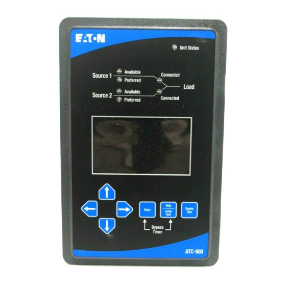
(Figure 2). The synchroscope is a useful tool for sync type transitions. When All wiring connections to the ATC-900 are made at the rear of the the controller is waiting for synchronization for either In-phase or chassis. - Page 7 Automatic Transfer Switch Controller, ATC-900 1. ATC-900 Faceplate (UV resistant) 6. Help Pushbutton (provides help information in any operational mode) 2. Operational Mode LEDs (highlighting ATC-900’s pres- ent operational condition) 7. Arrow Pushbuttons (used individually, pushbuttons move through displayed information and adjust set- 3.
- Page 8 DCT Module part number 70C1778G01 I/O module part number 70C1776G01 Figure 2. ATC-900 (Top Left, and Right Side Views). color display on the front of the ATC-900. Readings can also be 2.5 External Hardware monitored through the RS-485 modbus on the controller. The DCT...
- Page 9 Instructional Booklet Effective: March 2021 Page 9 Operation and Maintenance Manual, Automatic Transfer Switch Controller, ATC-900 Table 1. Current, Voltage, Frequency, Metering Data. CURRENT METERING UNITS ACCURACY NOTES lA, lB, IC, Amperes ±1% of Accuracy applicable for 5 to 100% of I,...
- Page 10 DC wetted (24 Volts at 10 ma) connections for various functional inputs. See ATC-900 via an Ethernet network. The Ethernet Module provides Figure 4 and Figure 5. Up to four modules can be used with the ATC-900 giving Ethernet TCP/IP. The J12 connection will be utilized for the Ether- the user up to 20 inputs or 20 outputs (including the controller's standard I/Os).
- Page 11 Instructional Booklet Effective: March 2021 Page 11 Operation and Maintenance Manual, Automatic Transfer Switch Controller, ATC-900 Refer to Table 3. 2.6 Specification Summary Table 3. ATC-900 Specifications. PARAMETER SPECIFICATION Power Isolation Requirements: • Control power for Source 1, J7-1,2 must be electrically isolated from control power for Source 2, J7-3,4.
-
Page 12: Operator Panel And Display Menus
The test engine run timer will hold the functions. The LED at the top of the ATC-900 provide a quick snap- load for the required timeout and the test is concluded with a re- shot of the unit’s status (Mode). - Page 13 Automatic Transfer Switch Controller, ATC-900 d. Screen 4 Setpoints - Switch Type Settings (4 of 4) 3.4 Display and Menus The ATC-900 provides a comprehensive array of monitored param- View Setpoints Time Delays eters, setpoints, and messages via its easy to read Color Display a.
- Page 14 Instructional Booklet Page 14 Effective: March 2021 Operation and Maintenance Manual, Automatic Transfer Switch Controller, ATC-900 v. PE2 Day vi. Exerciser 2 Dates 5. View Setpoints Prog I/O a. Screen 1 Setpoints Programmable Inputs (1 of 2) i. Main Input 1 ii.
-
Page 15: Operation
This section specifically describes the operation and functional Vdc. Each contact input (same for I/O Module) provides a wetted use of the ATC-900. It is divided into three main categories: 24 Vdc at 10 mA. Refer to Figure 2 for a graphical representation •... - Page 16 UPS if desired. Emergency Source will be initiated. If the Emergency Source fails and the Normal Source is available, the ATC-900 will initiate a The Primary ATS handles all transfer time delays between the Util- transfer back to the Normal Source (failsafe).
- Page 17 (Device) by simply changing the setpoint. See Tables 4 and 5 All enabled and programmed time delays will be performed per the below .This allows the ATC-900 controller to be completely pro- grammable by the end user with all options available. It cannot be setpoints during an engine test.
-
Page 18: Setpoint Programming And I/O Programming Using The Color Display
I/Os can be used with ATC-900 is a Monitoring Protection and Control Communications the ATC-900. That is a total of 20 Input and Outputs that can be compatible device. As such, it can be remotely monitored, con- user programmed. - Page 19 Automatic Transfer Switch Controller, ATC-900 Figure 8. Load Metering. B. View Setpoints Figure 7d. ATC-900 Unprogrammed Switch Type Main Screen. This will allow the user to view the: Figure 7e shows the screen for setting the Switch Type. Once • System Setups: selected, the up/down arrow keys cycle through Switch Types •...
- Page 20 POINTS WILL AUTOMATICALLY CHANGE ALL THE PICKUP AND DROPOUT SETTINGS TO NEW DEFAULT VALUES. All ATC-900 programmable features and associated setpoint pos- sibilities with any required explanations are presented in Table 7. As mentioned earlier, when "Change Setpoints" is selected, the display will show the following icons: •...
- Page 21 Effective: March 2021 Page 21 Operation and Maintenance Manual, Automatic Transfer Switch Controller, ATC-900 Figure 11. Setting Setpoints. All setpoints, are set in this way. The display gives the user a quick look at not just one setpoint but the whole catagory on one screen.
- Page 22 Instructional Booklet Page 22 Effective: March 2021 Operation and Maintenance Manual, Automatic Transfer Switch Controller, ATC-900 Table 7. Programmable Features/Setpoints. Time delay post-transfer 0–120 seconds 0:10 Table 7 is continued in column 2 of this page OPTION FACTORY NUMBER DESCRIPTION...
- Page 23 Operation and Maintenance Manual, Automatic Transfer Switch Controller, ATC-900 5.5 Programming I/Os The ATC-900 has four inputs and four outputs that are program- • Engine Start Contact Status (Gen 1 & 2) mable I/Os. The outputs are Form C types and easily assessable.
- Page 24 See Appendix B for more information and definitions. This IB is updated during the year but some features may not be shown because of the time element of the IB getting published. Eaton is constantly adding in more features to the ATC-900. As men- tioned, the user will receive all software features except for the optional closed transition.The "P"...
- Page 25 Instructional Booklet Effective: March 2021 Page 25 Operation and Maintenance Manual, Automatic Transfer Switch Controller, ATC-900 Table 8. ATC-900 Features and I/O (Cont.). ATC-900 FEATURES CONTACTOR MCCB MAGNUM ATC9 BIC9 CBC9 CTC9 ATx9 ATV9 CBV9 P = Programmable (Internal or I/O), PF = Prgammable Fixed I/O...
- Page 26 Instructional Booklet Page 26 Effective: March 2021 Operation and Maintenance Manual, Automatic Transfer Switch Controller, ATC-900 Table 8. ATC-900 Features and I/O (Cont.). ATC-900 FEATURES CONTACTOR MCCB MAGNUM ATC9 BIC9 CBC9 CTC9 ATx9 ATV9 CBV9 P = Programmable (Internal or I/O), PF = Prgammable Fixed I/O...
- Page 27 Instructional Booklet Effective: March 2021 Page 27 Operation and Maintenance Manual, Automatic Transfer Switch Controller, ATC-900 Table 8. ATC-900 Features and I/O (Cont.). ATC-900 FEATURES CONTACTOR MCCB MAGNUM ATC9 BIC9 CBC9 CTC9 ATx9 ATV9 CBV9 P = Programmable (Internal or I/O), PF = Prgammable Fixed I/O...
-
Page 28: Troubleshooting And Maintenance
For assistance with this determination, con- switch system troubleshooting will be performed. If the cause of tact Eaton. If a problem is identified to be external to ATC-900, malfunction is traced to an ATC-900, the malfunctioning unit proceed to Section 6.3 and continue troubleshooting. - Page 29 If a problem persists after having completed the problem solving DEALER. IF THE RESULT IS NOT CORRECTED, CONTACT THE procedure, contact an Eaton representative for further assistance. EATON ATS TECHNICAL SUPPORT AT 1-877-386-2273. When calling for assistance, the following is the minimum infor- 6.3 General Switch Problem Solving...
- Page 30 If NO: Proceed to Step 9. ponents after the cause is determined. Step 8: If a problem persists, contact Eaton. Step 5: Is switch closed on source 1? Verify whether or not the system voltage now appears on the load terminals.
- Page 31 Step 7: Mount the replacement unit. Step 10: If this is a Magnum measure the voltage between termi- Step 8: Secure the ATC-900 to the panel with the 6 mounting nals B12 and B13 on the Non-preferred switching device screws.
-
Page 32: Historical & Event Display
Automatic Transfer Switch Controller, ATC-900 Section 7: Historical & Event Display Event Summary The ATC-900 event and data logging history can be read on the ATC-900's display or downloaded to a USB thumb drive. Every ATC-900 transfer switch includes a front panel mounted NEMA 4X rated USB port for use in uploading downloading setpoints and event data. - Page 33 All files except firmware upgrades are viewable using a CSV file viewer such as Microsoft Excel, Notepad, or OpenOffice Note: if the USB drive has never been connected to an ATC-900 controller Calc. before, it will automatically create the required folder structure.)
-
Page 34: Appendix A: Feature List And Status Display Messages
If the generator fails during testing for any reason, the TDEN delays the transfer to the Preferred Source to permit stabili- ATC-900 will signal the transfer switch to return to normal. The zation of the Preferred power source before the transfer is made. - Page 35 Emergency Source, the Voltage Unbalance Monitoring for Source 2 ATC-900 will constantly be waiting and attempting to start the This feature constantly monitors Source 2 for a voltage unbalance generator on the Preferred Source so that it may return to it. If condition using symmetrical components calculations.
- Page 36 If the generator fails during testing for any rea- can be disabled in the setpoint settings under menu 3 in the Set- son, the ATC-900 will signal the transfer switch to return to the points Dropouts/Pickups. Preferred source. The ATC-900 is factory shipped with this fea- Feature 29J: Manual Retransfer ture set to off.
- Page 37 Feature 35D: Post-Transfer Signal via Modbus RTU through an RS-485 port. Registers are available This feature provides a form C output from the ATC-900 to signal to read back status, voltages, frequencies, and historical data. that the switch did transfer. It can be set for 0 to 120 seconds.
- Page 38 • Secondary In - Indicates when its generator(s) should be run- ning. Real Time Clock The ATC-900 has a battery backed real time clock to track date and time. The date and time can be set through the front panel Secondary Generator Startup/Shutdown Operation System Info / Set Time &...
- Page 39 Instructional Booklet Effective: March 2021 Page 39 Operation and Maintenance Manual, Automatic Transfer Switch Controller, ATC-900 Secondary Controller with Preferred Source Secondary-In goes Active -Immediately turn on Preferred Source Gen Start -Start Emergency Source TDES counting down -Set transfer switch to Preferred Source (No TDN or TDEN if...
- Page 40 Instructional Booklet Page 40 Effective: March 2021 Operation and Maintenance Manual, Automatic Transfer Switch Controller, ATC-900 Secondary Controller with No Preferred Source Secondary-In goes Active -Immediately turn on Gen Start for both Sources -Set transfer switch to Source 1 (No TDN or TDEN if switch...
- Page 41 Instructional Booklet Effective: March 2021 Page 41 Operation and Maintenance Manual, Automatic Transfer Switch Controller, ATC-900 Appendix A: Feature List and Status Display Messages RED BAR FLASHING MESSAGES ALL RED BARS ARE GENERAL ALARMS Lockout Automatic control is disabled but still monitors source status. User must reset...
- Page 42 Instructional Booklet Page 42 Effective: March 2021 Operation and Maintenance Manual, Automatic Transfer Switch Controller, ATC-900 YELLOW BAR FLASHING MESSAGES Overvoltage Indication of Overvoltage (not withing setpoint setting) Undervoltage Indication of Undervoltage (not withing setpoint setting) Underfrequency Indication of Underfrequency (not withing setpoint setting)
-
Page 43: Appendix B: I/O Descriptions
Secondary ATS. The Secondary input receives the engine start signal from the Primary controller. S1 Available The ATC-900 will measure voltage and frequency and if they are measured in the envelope of the settings an Output will show that S1 is Available... - Page 44 Load Restore setpoint is attained. The DCT module is required for current measurements. User to set kV and time values. General Alarm Indication Provides remote indication that an alarm condition exists on the ATC-900. Remains on until all alarms are resolved and reset at the controller. contact Monitor Mode Provides remote indication that the ATS is not in automatic mode.
-
Page 45: Appendix C: Operational Flowcharts
Instructional Booklet Effective: March 2021 Page 45 Operation and Maintenance Manual, Automatic Transfer Switch Controller, ATC-900 Appendix C: Operational Flowcharts • Open Delayed Transition (Contactor, MCCB, Power) • Open In-Phase Transition (Contactor, Power) • Closed Transition (Contactor, Power) • The use of TDND, TDNR, TDED, and TDER timers. - Page 46 Instructional Booklet Page 46 Effective: March 2021 Operation and Maintenance Manual, Automatic Transfer Switch Controller, ATC-900 For more information visit: www.eaton.com IB140012EN...
- Page 47 Page 47 Operation and Maintenance Manual, Automatic Transfer Switch Controller, ATC-900 Note: There are options for closed transition such as Closed Transition and Closed Transition to Load Decay or Time Delay Neutral. There is settable input (Closed Transition Inhibit) that if closed, will inhibit closed transition and switch to the open type.
- Page 48 Instructional Booklet Page 48 Effective: March 2021 Operation and Maintenance Manual, Automatic Transfer Switch Controller, ATC-900 TDND/TDNR & TDED/TDER Timers Transition Flowchart Example Normal Available, Commit to Transfer Off (Clear TDND/TDNE) Normal Unavailable Connect to Connect Emergency Available Normal Normal Unavailable Normal TDND >...
- Page 49 Instructional Booklet Effective: March 2021 Page 49 Operation and Maintenance Manual, Automatic Transfer Switch Controller, ATC-900 Normal Available Connect to Connect Emergency Available TDEN = 0 Emergency TDEN > 0 Emergency Emergency Connected to Unavailable Emergency (fail-safe transfer) TDEN Normal Unavailable...
- Page 50 DEALING OR USAGE OF TRADE, ARE MADE REGARDING THE INFORMATION, RECOMMENDATIONS, AND DESCRIPTIONS CONTAINED HEREIN. In no event will Eaton be responsible to the purchaser or user in contract, in tort (including negligence), strict liability or otherwise for any special, indirect, incidental or conse-...
Need help?
Do you have a question about the ATC-900 and is the answer not in the manual?
Questions and answers
If the ATC-900 ATS fails does it automatically switch to the automatic bypass or does this have to be manually put in bypass for the bypass to work like a 2nd ATS?
The Eaton ATC-900 ATS does not automatically switch to bypass mode upon failure. Bypass operation requires manual activation using the operating panel or controls.
This answer is automatically generated