Table of Contents
Advertisement
Quick Links
BR081012EN
Diesel Engine
Additive (Foam) Pump Controllers
Product Description
The DIESEL Plus Foam Pump
Controllers from Eaton are designed
to control and monitor 12 or 24
volt, diesel fi re pump engines and
are among the most technically
advanced diesel engine controllers
available.
They are an enhanced version
of the original microprocessor-
based, FD100 Series of diesel
engine controllers. Programming is
straightforward due to the use of the
core fi rmware and menu structure
utilized in the LMR Plus Series of
electric controllers.
The controller can be ordered with
the option to display and output
current values and status, on
command, from various software
protocols.
An embedded web page for
retrieving diagnostics and history
reports, can be accessed from the
optional Ethernet communication
port. An optional RS485 serial port
can be used for direct connection to
a computer for data transfer.
Product Features
Communication
Embedded Web Page
The embedded web pages allow the
user to view the current status of
the controller as well as all amper-
age readings, set points, diagnostics,
statistics, confi guration and history.
An external computer connected via
the optional ethernet port is used to
access the pages. The specifi c data
required can be downloaded for
reference purposes.
Communication Types
USB
The USB port is used to download the
controller message history, statistics,
diagnostics, status and confi guration
data to a USB disk drive. The USB
port can also be used to upload cus-
tom messages, additional languages,
and update the microprocessor
fi rmware.
Ethernet
An external computer can commu-
nicate with the Diesel Plus controller
via the optional ethernet port. An
embedded web page will display
the controller's current status, as well
as display all current readings, set
points and history.
Modbus
The Diesel Plus foam pump control-
lers have the option to communi-
cate to systems using the Regular
level of Modbus (includes both RTU
and ASCII transmission modes).
Communication settings are user
confi gurable through the Diesel Plus
confi guration menu.
Field Connections
Standard Inputs
•
Remote Start
•
Fuel Spill
•
Deluge Valve
•
Low Foam Level
•
Interlock On
•
Remote Auto Start
•
Low Fuel
•
Programmable Inputs (9)
Programmable Inputs
Up to 9 additional, programmable in-
puts can be programmed to indicate
up to 13 diff erent types of inputs.
They can be programmed to energize
the common alarm output, link to
relays and optional LED's and latch
until reset by the user.
All optional inputs, outputs and LED's
can be linked, as required. They can
also be programmed with time delay
functions.
Eff ective April 2015
Standard Output Relays
All standard output relays are 8 amp,
DPDT.
•
Interlock On
•
Future # 2
•
Low Fuel
•
Auto Mode
•
Common Alarm
Optional Output Relays
There is provision to add up to eight
additional relay outputs, via four
optional relay output boards which
mount in a snap-on confi guration.
Each board contains a maximum of 2
additional relays.
Engine Run Relay
The Power I/O Board houses a 10
Amp engine run relay which is used
for alarm purposes, or to power
external louvers.
Common Alarm Relay
The FDF120 controller has a com-
mon alarm relay which de-energizes
whenever there are any alarm condi-
tions present. This relay is energized
under normal conditions and has LED
status indication.
Alarm Relay Rating
All alarm relays are rated 8 amps,
250Vac, resistive load only.
Programmable Outputs
Up to 10 additional, programmable
outputs (two standard; eight via
optional output boards) can be
programmed to indicate up to 45
output conditions. They can be pro-
grammed for fail safe and latch until
reset by the user. All optional inputs,
outputs and LED's can be linked, as
required. They can also be pro-
grammed with time delay functions.
As well, two optional alarm LED's can
be programmed for up to 28 alarm
conditions.
FDF120 Diesel Engine Controllers
Power / Voltage
Universal Voltage Supply
The controller can be powered with
supply voltages from 100Vac to
240Vac by connecting to the three
input terminals L,N,G located on the
bottom left of the engine board.
Dual Output
12 or 24Vdc output is selectable via
a DIP Switch located on the battery
chargers. Note: Each controller is fac-
tory set for 12Vdc. If 24Vdc is required
from the factory, it should be noted
on the ordering information.
Line Filter
A line fi lter incorporated onto the
engine board, is used to reduce/
eliminate external incoming voltage
transients.
AC Power Disconnect
A breaker located inside the control-
ler on the Engine Board, is used
to switch on and off AC power to
the unit. It will illuminate when
energized.
DC Power Disconnect
The engine board houses two
on-board circuit breakers used to
switch on or off DC power from the
batteries.
Each breaker has an LED mounted
on the engine board that illuminates
when the breaker is energized.
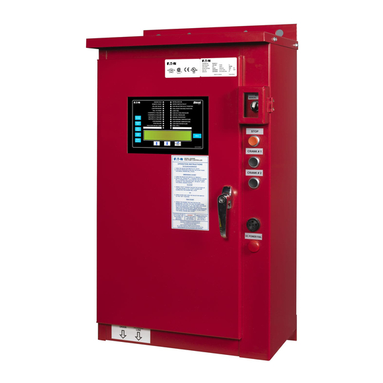
Alarm and Status
Indication
Accessibility
All alarm and status LED's as well as
the LCD Display and programming
buttons are accessible from the front
of the controller.
Advertisement
Table of Contents

Subscribe to Our Youtube Channel
Related Manuals for Eaton FDF120


Summary of Contents for Eaton FDF120
- Page 1 It will illuminate when Common Alarm Relay An embedded web page for energized. Standard Inputs The FDF120 controller has a com- retrieving diagnostics and history • Remote Start mon alarm relay which de-energizes DC Power Disconnect reports, can be accessed from the •...
- Page 2 • Output Voltage: 12-24Vdc in troubleshooting issues with the • Hertz: 50/60 Hz The FDF120 Diesel Engine Fire controller. The diagnostics can be • Enclosure: Pump Controllers meet or exceed viewed on the main display, saved...
- Page 3 Technical Data MD081016EN Dimensions Diesel Plus Foam Pump Controller Standard Enclosure - Type NEMA 2, 3R, (*4, 4X), 12 Eff ective April 2015 19.19 [487] 15.00 [381] 26.72 [679] 7.00 [178] 2.00 [51] 13.11 [333] ENGINE RUN INTERLOCK ON ENGINE RUN INTERLOCK ON REMOTE START SPEED SWITCH FAULT...
- Page 4 Technical Data MD081015EN Dimensions Diesel Plus Foam Pump Controller Main Display Eff ective April 2015 NOTES: 1. Refer to the DIESEL Plus technical manual for details and setup information, as well as programming and custom labeling for the Programmable LED’s.
- Page 5 Technical Data MD081014EN Dimensions Fuel Level Switch Diesel Plus Engine Controller Eff ective April 2015 3A14119G01: 16 inch unit 3A14119G02: 45 inch unit Dimensions in Inches...
- Page 6 Technical Data TD081021EN Electrical Wiring Schematic Diesel Plus Foam Pump Controller Eff ective April 2015 CUSTOMER INPUTS CUSTOMER INPUTS LOW FOAM LEVEL (2 SETS FORM-C) ENGINE RUN OPTION RELAY #2 (2 SETS FORM-C) ENGINE RUN INTERLOCK ON OPTION RELAY #3 (2 SETS FORM-C) INTERLOCK ON OPTION RELAY #4...
- Page 7 Technical Data TD081022EN Field Connections Diesel Plus Foam Pump Controller Eff ective April 2015 Field Connections Engine Board Terminal Blocks Inputs 100-240VAC POWER FUEL & WATER SOLENOID VALVE ENGINE RUN SW. OVERSPEED SW. OIL PRESSURE SW. ENGINE WATER TEMP. SW. BATTERY #1 INPUT(+) BATTERY #2 INPUT(+) BATTERY #1 CRANK...
- Page 8 Technical Data TD081023EN LMR Plus Fire Pump Controllers Wire & Cable Conversions Diesel Plus Engine Controllers Effective April 2015 Technical Data and Specifications - LMR Plus Electric Controllers Line Terminals on Main Isolation Switch (Incoming Cables) Qty. & Cable Sizes American Wire Gauge (AWG /MCM) Diameter (mm) (1)#14-1/0 PER Ø...
- Page 9 Technical Data PA081004EN Part Number / Options Selection Guide Diesel Plus Engine Controller Eff ective April 2015 FD120 FDF120 Language DIESEL Plus Options L1 = English 380* Supply Voltage (380V 50/60Hz) L2 = French 480* Supply Voltage (480V 60Hz) L4 = Italian...
- Page 10 Fire Pump Controllers Features Diesel Plus Fire Pump Controllers April 2015 Typical Specifications 5. Enclosure Approvals The controller shall be housed in a NEMA Type The Fire Pump Controller shall meet Factory 2 (IEC IP11) drip-proof, powder baked finish, Mutual Research (FM) 1321/1323. It shall be freestanding enclosure.
- Page 11 Fire Pump Controllers Features Diesel Plus Fire Pump Controllers April 2015 C. The controller shall have a 4 line by 40 character Remaining time left on active timers. LCD display mounted on a panel opening in the D. The controller shall be supplied with six (6) front door.
- Page 12 LED’s to ensure their functionality. 7. Programming Menu The controller shall be microprocessor based as manufactured by Eaton Industries (Canada) The programming menu shall have the ability to enable an entry password. The programming menu shall be limited to two (2) levels of password protection.
- Page 13 O & M Manual IM05805019K-002 Effective April 2015 EATON Diesel Plus Diesel Engine Fire Pump Controller Powering Business Worldwide...
-
Page 14: Table Of Contents
9.4 Weekly Exerciser Test ..........31 4.3.2 Control Input Descriptions ........9 4.3.3 Loss of DC Power ..........10 4.3.4 Speed Switch Malfunction ........10 4.3.5 Engine Starter Coil Failure ........10 4.3.6 Audible Alarm Silencing........10 4.3.7 Power Failure Alarm ..........10 EATON INDUSTRIES CANADA COMPANY www.chfire.com... -
Page 15: Introduction
The connection should be installed as per NFPA, 20. regarding the information, recommendations and descriptions contained herein. In no event will EATON be responsible to the The pressure sensor and internal plumbing components are purchaser or user in contract, in tort (including negligence), rated for a maximum of 500 PSI. -
Page 16: Wire Sizes
Battery chargers are independent of each other and produce a maximum of 10 amps each at full rate. Each battery charger is fully electronic and will protect itself by shutting down during a short circuit condition. EATON INDUSTRIES CANADA COMPANY www.chfire.com... -
Page 17: Ac Input Fuse Protection
OFF position. • Alert the user to specific conditions 12 Volt - NiCad 12 Volt - NiCad • Program the controller • Set and monitor the operating parameters • Perform a manual start of the controller. EATON INDUSTRIES CANADA COMPANY www.chfire.com... -
Page 18: The Leds
The “Home” screen display will show the current date and when the controller receives a signal from the engine time, current pressure, Battery #1 voltage and charging amps, indicating there is a fuel injection malfunction. (Terminal 302) EATON INDUSTRIES CANADA COMPANY www.chfire.com... -
Page 19: Pushbuttons
If the alarm condition still exits it will alarm again. When the user is in the programming mode, pressing the save/exit button will save all of the user adjusted values and make the recent changes active. EATON INDUSTRIES CANADA COMPANY www.chfire.com... -
Page 20: External Pushbuttons
OFF mode. The engine will automatically stop in the case of an OVERSPEED condition. All alarms, except for “FAIL TO START” , are active in the MANUAL mode. EATON INDUSTRIES CANADA COMPANY www.chfire.com... -
Page 21: Run Period Timer
These are programmable inputs and will function based on how they are programmed. Refer to Appendix E(a) for The Control Input state definitions are as follows. programming details. Connected - When the input is shorted by an external contact or connection. EATON INDUSTRIES CANADA COMPANY www.chfire.com... -
Page 22: Loss Of Dc Power
All Diesel Plus controller programmable features and associated set-point possibilities are presented in Table 1. The following set points are programmable in the Diesel Plus controller. EATON INDUSTRIES CANADA COMPANY www.chfire.com... - Page 23 English, French, or Spanish. A fourth language can be pressure stop point, low pressure alarm, and high pressure added utilizing the USB port. Consult Eaton for available alarm set-points will be removed from the menu system. languages. Refer to for programming.
- Page 24 RESTRICT STARTING OR STOPPING OF THE FIRE PUMP UNLESS REQUIRED timing, the time left will be displayed on the fourth line of the BY THE AHJ. EATON CORPORATION ASSUMES NO LIABILITY WHEN THIS display. The SST will not work on Remote Starts.
- Page 25 Electronic Control Module Warning associated future inputs and/ or lights linked to the output. Electronic Control Module Failure Please refer to Table 3 for the generic values the optional High Raw Water Temperature EATON INDUSTRIES CANADA COMPANY www.chfire.com...
-
Page 26: History, Diagnostics, Statistics, Configuration
Crank Battery #2 Last Low Pressure Start Date & Time Coil #1 Failure Minimum Battery #1 Voltage Unlimited Coil #2 Failure Minimum Battery #2 Voltage Unlimited Maximum Battery #1 Voltage Unlimited Maximum Battery #2 Voltage Unlimited EATON INDUSTRIES CANADA COMPANY www.chfire.com... -
Page 27: Controller Diagnostics
• Refer to Appendix H to upload and enable the custom Diagnostic values that are recorded are the current date and messages. time, the microprocessor’s firmware version, Eaton’s shop order number, customer order number, voltage readings, • Refer to Section 8 for the creation of the custom message file. -
Page 28: Rs485 Serial Port (Optional)
Column B contains the message type reference number. Refer to Table 7 for the message types. Table 7. Custom Message Types Number Description Specific date and time range Number of pump start events Number of hours run Specific alarms Common Alarms EATON INDUSTRIES CANADA COMPANY www.chfire.com... - Page 29 Low Pressure Low Engine Temperature Low Room Temperature Fuel Spill Low Suction Common Alarm (5) No other points are required to be entered into the spreadsheet, as this message will appear anytime there is an alarm. EATON INDUSTRIES CANADA COMPANY www.chfire.com...
-
Page 30: Appendix A: Main Menu Tree
GO TO SETTINGS APPENDIX B PRESSURE GO TO SETTINGS APPENDIX C GO TO TIMER VALUES APPENDIX D CUSTOM GO TO INPUT/OUTPUT APPENDIX E SYSTEM CONSULT CONFIG MENU FACTORY MAIN MENU GO TO PASSWORD APPENDIX F EATON INDUSTRIES CANADA COMPANY www.chfire.com... -
Page 31: Appendix B: Regional Settings Menu Tree
APPENDIX B: REGIONAL SETTINGS MENU TREE REGIONAL SETTINGS SET DAY OF MENU CHANGE DATE SET MONTH SET DAY SET YEAR WEEK NEXT MENU ITEM MENU CHANGE TIME SET HOUR SET MINUTES NEXT MENU ITEM NEXT MENU ITEM EATON INDUSTRIES CANADA COMPANY www.chfire.com... -
Page 32: Appendix C: Pressure Settings Menu Tree
SET AUTOMATIC MENU SUCTION SHUTDOWN DELAY MODE RESET TIME SHUTDOWN NEXT MENU ITEM PRESSURE SET PRESSURE MENU NEXT MENU ITEM DEVIATION DEVIATION HOURLY SET HOURLY MENU PRESSURE PRESSURE NEXT MENU ITEM RECORDING RECORDING NEXT MENU ITEM EATON INDUSTRIES CANADA COMPANY www.chfire.com... -
Page 33: Appendix D: Timer Values Menu Tree
SET RUN TIME ALARM ALARM TIMER AC FAILURE SET AC FAIL NEXT MENU ITEM MENU NEXT MENU ITEM START START TIMER SEQUENTIAL SET SEQUENTIAL MENU NEXT MENU ITEM START TIMER START TIMER NEXT MENU ITEM EATON INDUSTRIES CANADA COMPANY www.chfire.com... -
Page 34: Appendix E: Custom Input/Output Menu Tree
Effective April 2015 APPENDIX E: CUSTOM INPUT/OUTPUT MENU TREE CUSTOM INPUT/ OUTPUT CUSTOM GO TO MENU INPUTS APPENDIX E(a) CUSTOM GO TO MENU OUTPUTS APPENDIX E(b) CUSTOM GO TO MENU LIGHTS APPENDIX E(c) NEXT MENU ITEM EATON INDUSTRIES CANADA COMPANY www.chfire.com... -
Page 35: Appendix E(A): Custom Inputs Menu Tree
A C K A C K N E X T M E N U IT E M T IM E R T IM E N E X T M E N U IT E M EATON INDUSTRIES CANADA COMPANY www.chfire.com... -
Page 36: Appendix E(B): Custom Outputs Menu Tree
SET AUDIBLE MENU NEXT MENU ITEM ALARM ALARM MENU FAIL SAFE SET FAIL SAFE NEXT MENU ITEM SET DELAY SET TIMER SET DELAY MENU DELAY TIMER NEXT MENU ITEM TIMER STYLE TIME NEXT MENU ITEM EATON INDUSTRIES CANADA COMPANY www.chfire.com... -
Page 37: Appendix E(C): Custom Lights Menu Tree
EATON Diesel Plus O & M Manual IM05805019K-002 Diesel Engine Fire Pump Controller Effective April 2015 APPENDIX E(c): CUSTOM LIGHTS MENU TREE CUSTOM LIGHTS MENU SELECT LIGHT MENU SELECT TYPE EATON INDUSTRIES CANADA COMPANY www.chfire.com... -
Page 38: Appendix F: Main Menu Password Menu Tree
EATON Diesel Plus Diesel Engine Fire Pump Controller Effective April 2015 APPENDIX F: MAIN MENU PASSWORD MENU TREE MAIN MENU MENU PASSWORD SELECT SELECT SELECT SELECT SELECT PASSWORD BUTTON #1 BUTTON #2 BUTTON #3 BUTTON #4 EATON INDUSTRIES CANADA COMPANY www.chfire.com... -
Page 39: Appendix G: Custom Message Load & Activation
Effective April 2015 APPENDIX G: CUSTOM MESSAGE LOAD & ACTIVATION SELECT CUSTOM DATA MESSAGES CUSTOM MESSAGES SELECT LOAD WILL BE UPLOADED SELECT CUSTOM DATA MESSAGES SELECT MESSAGE SELECT ENABLE/ SELECT VIEW TO ENABLE/DISABLE DISABLE MENU EATON INDUSTRIES CANADA COMPANY www.chfire.com... - Page 40 • For control wiring, use #14 AWG wire for all electrical connections except battery connections. • For battery connection, terminals 6, 7, 8 and 11, use the following: #10 AWG: 0' to 25' (7.62 m) # 8 AWG: 25' to 50' (15.2 m) EATON INDUSTRIES CANADA COMPANY www.chfire.com...
-
Page 41: Appendix L: Alarm/Status Messages
Low Suction Shutdown The controller has shutdown because of low suction Manual Crank #1 The Controller was started via the Manual Crank button. Manual Crank #2 The Controller was started via the Manual Crank button. EATON INDUSTRIES CANADA COMPANY www.chfire.com... -
Page 42: Initial Start Up
Should the engine fail to start after 6 crank and rest cycles, the audible alarm will sound and the “Fail To Start” annunciator will illuminate. Turning the mode selector switch to the “OFF” position will silence the alarm. When engine starts, “Engine Run” annunciator illuminates. EATON INDUSTRIES CANADA COMPANY www.chfire.com... -
Page 43: Engine Test
At the programmed time and date the drain valve solenoid will open. The Engine will crank and start. The “Engine Run” annunciator will illuminate.and the drain valve solenoid will close. Press the STOP pushbutton. The engine will stop. Reprogram Weekly Exerciser for normal operation. EATON INDUSTRIES CANADA COMPANY www.chfire.com... - Page 44 COURSE OF DEALING OR USAGE OF TRADE, ARE MADE REGARDING THE INFORMATION, RECOMMENDATIONS AND DESCRIPTIONS CONTAINED HEREIN. In no event will EATON be responsible to the purchaser or user in contract, in tort (including negligence), strict liability or otherwise for any...
Need help?
Do you have a question about the FDF120 and is the answer not in the manual?
Questions and answers