Advertisement
Instructions for Installation, Operation
and Maintenance of the
Eaton ATC-600 Automatic
Transfer Switch Controller
Instructional Booklet
Description
1. Introduction . . . . . . . . . . . . . . . . . . . . . . . . . . . . . . . 2
2. Hardware Description . . . . . . . . . . . . . . . . . . . . . . . . 7
3. Operator Panel . . . . . . . . . . . . . . . . . . . . . . . . . . . . . 11
4. Operation . . . . . . . . . . . . . . . . . . . . . . . . . . . . . . . . . 14
5. Programming . . . . . . . . . . . . . . . . . . . . . . . . . . . . . . 19
6. Troubleshooting and Maintenance . . . . . . . . . . . . . . . . 22
Appendix A: Status Display Messages . . . . . . . . . . . . . 27
Appendix B: Historical Display Information . . . . . . . . . . 28
Appendix C: Time/Date Display Information . . . . . . . . . 30
Appendix D: ATC-600 Menu Tree . . . . . . . . . . . . . . . 31
Appendix E: Operational Flowcharts . . . . . . . . . . . . . . . 33
IB ATS-1005
Page
For more information visit: www.eaton.com
Advertisement
Table of Contents

Related Manuals for Eaton ATC-600


Summary of Contents for Eaton ATC-600
-
Page 1: Table Of Contents
Appendix C: Time/Date Display Information ..30 Appendix D: ATC-600 Menu Tree ....31 Appendix E: Operational Flowcharts ....33 IB ATS-1005 For more information visit: www.eaton.com... -
Page 2: Introduction
TROL DEVICES WITHOUT CONSULTING THE FACTORY. of the ATC-600. It is provided as a guide for authorized and quali- fied personnel only in the selection and application of the ATC- All possible contingencies which may arise during installation, 600. - Page 3 1. Main contacts to connect and disconnect the load to and from 1.4 Functions/Features/Options the source of power The primary function of ATC-600 is to accurately monitor power 2. A transfer mechanism to affect the transfer of the main con- sources and provide the necessary intelligence to operate a trans- tacts from source to source fer switch in an appropriate and timely manner.
- Page 4 Standard Feature: Undervoltage Monitoring for Source 1 (1UVD, the features is made. 1UVP) ATC-600 features with a brief description follow. The actual pro- This feature constantly monitors Source 1 for an undervoltage grammable setpoints for each feature are covered in Section 5.
- Page 5 If the generator fails during testing for any reason, the Standard Feature 26F: Overfrequency Monitoring for Source 1 ATC-600 will signal the transfer switch to return to normal. If dis- (1OFD, 1OFP) able test mode is chosen, the front panel pushbutton cannot be This feature constantly monitors Source 1 for an overfrequency used to initiate a test.
- Page 6 Should the permissive signal not be used or does not occur, the ATC-600 has a programmed overriding pre-transfer delay timer that can be set from 0 to 5 min- utes.
-
Page 7: Hardware Description
The rear access area of the ATC-600 is normally accessible from the rear of an open panel door (Figure 2). All wiring connections to the ATC-600 are made at the rear of the chassis. For the sake of uniform identification, the frame of refer- ence when discussing the rear access area is facing the back of the ATC-600 with the panel door open. - Page 8 Instructional Booklet Page 8 Effective: March 2010 Instructions for Installation, Operation and Maintenance of the Eaton ATC-600 Automatic Transfer Switch Controller 1. ATC-600 Faceplate (UV Resistant) 7. Increase/Decrease Pushbuttons (used individually, pushbuttons move displayed information/setting up or 2. Operational Mode LEDs (highlighting ATC-600’s down through all possibilities –...
- Page 9 Communications is made possible by mounting a small, addressable communication module (PONI) to the back of the ATC-600 (Figure 3) or in a remote location. Since the ATC- 600 is always supplied with a communications port, a PONI can be easily retrofitted to the ATC-600 at any time.
- Page 10 Instructional Booklet Page 10 Effective: March 2010 Instructions for Installation, Operation and Maintenance of the Eaton ATC-600 Automatic Transfer Switch Controller 2.5 Specification Summary Refer to Table 1. Table 1. ATC-600 Specifications PARAMETER SPECIFICATION Control Power: • 120Vac (50/60 Hz) (operating range 65 to 160 Vac) Power Consumption: •...
-
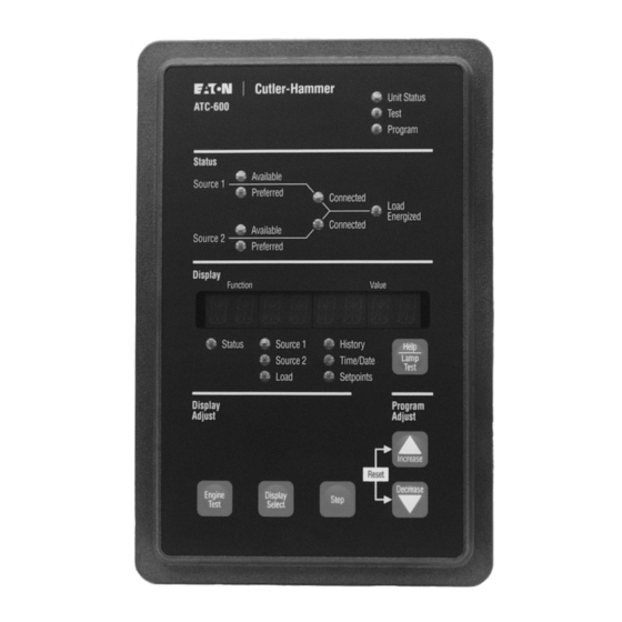
Page 11: Operator Panel
Source 1 - Display LED functions. Three LEDs at the top of the ATC-600 provide a quick This LED is lit green when displaying Source 1 voltage, frequency, snapshot of the unit’s status (Mode). Seven LEDs, just above the and status information. - Page 12 600 steps through the following display categories: The right rear mounted Run/Program Toggle Switch establishes whether the ATC-600 is in the Run Mode or the Program Mode. • Status Normally the switch is set in the Run position to permit normal •...
- Page 13 Eaton ATC-600 Automatic Transfer Switch Controller 3.4 Display Window The ATC-600 provides a comprehensive array of monitored param- eters, setpoints and messages via its easy to read Display Win- dow. Up to eight large characters are used to convey a wealth of information.
-
Page 14: Operation
TION NO MATTER WHICH MODE THE DEVICE IS IN AT THE TIME IT IS CALLED UPON TO OPERATE. NOTICE REFER TO APPENDIX D FOR AN OVERALL VIEW OF ATC-600 OPER- ATIONS IN THE FORM OF A MENU TREE. 4.2 Automatic Mode... - Page 15 IMPACC communications network this sys- Go To Emergency tem will allow the ATC-600 to be a master to Addressable Relay This input is located on Pins 7 and 8 of Connector J4. When the IIs that accomplish the Pre-transfer and Load Sequencing fea- external contact is closed, a transfer to the Emergency Source will tures.
- Page 16 Use a 100 ohm 1/2 watt terminating resistor on the most remote device. Where devices are daisy chained, tie the shielding together for continuity. Tie the shield to connector J4 terminal 17 of the ATC-600. On the last device in the network tie the shield back and tape. ...
- Page 17 • Customer Connections relays but only the Form A contacts are used to operate the trans- fer switch. • Transfer Operation Contacts Note: The ATC-600 Controller MUST BE properly grounded at J-5, Pin 5 4.5.1 Customer Connections for proper operation. S2 Generator...
- Page 18 The K4 relay the Run/Program switch on the rear of the chassis has been momentarily energizes until the ATC-600 senses that the Source 2 moved to the Program position. Any operator associated with pro- breaker is closed, then K4 de-energizes.
-
Page 19: Programming
NOTICE (0.0 to 3.0 Hz). When these conditions are met, the ATC-600 will monitor the phase difference between the two sources. The WHEN THE TOGGLE SWITCH IS IN THE PROGRAM POSITION, synchronization timer will count down and be displayed as “TSIP”... - Page 20 Eaton ATC-600 Automatic Transfer Switch Controller 5.4 Programmable Features/Setpoints CAUTION All ATC-600 programmable features and associated setpoint pos- sibilities with any required explanations are presented in Table 2. CHANGING THE SYSTEM NOMINAL VOLTAGE OR FREQUENCY SET- Remember, only features originally ordered and factory pro- POINTS WILL AUTOMATICALLY CHANGE ALL THE PICKUP AND DROPOUT SETTINGS TO NEW DEFAULT VALUES.
- Page 21 Instructional Booklet Effective: March 2010 Page 21 Instructions for Installation, Operation and Maintenance of the Eaton ATC-600 Automatic Transfer Switch Controller Table 2. Programmable Features/Setpoints (Cont.) PROGRAMMABLE DISPLAY SETPOINT FACTORY DEFAULT FEATURE DISPLAY EXPLANATION POSSIBILITIES VALUE MEASURE PHASE Number of System Phases...
-
Page 22: Troubleshooting And Maintenance
If the cause of FOR INFORMATION PERTAINING TO THE SOFTWARE VERSION AND malfunction is traced to an ATC-600, the unit should be replaced OPTIONS INCLUDED IN THE SPECIFIC UNIT. REFER TO THE “NOTE” with a spare. The malfunctioning unit should then be returned to UNDER THE TOPIC “HELP PUSHBUTTON”... - Page 23 Eaton. If a problem is identified to be internal, the unit should be returned to the factory for repair or replacement. If a problem is identified to be external to ATC-600, proceed to Sec- tion 6.3 and continue troubleshooting.
- Page 24 If a problem persists after having completed the problem solving procedure, contact an Eaton representative for further assistance. If NO: Proceed to Step 2. When calling for assistance, the following is the minimum informa- Step 2: Is Option 9B installed? If so, there would be a selector tion required to properly address the need: switch labeled “Maintenance.”...
- Page 25 If NO: Check the wiring to B12 and B13. Step 9: Measure the voltage between terminals B10 and B11 on Step 11: If a problem persists, contact Eaton. the NORMAL switching device (shunt trip). Is the volt- age measured 120 Vac (+/- 10 volts)? Record the read- 6.3.3 Transfer Switch Will Not Automatically Transfer To...
- Page 26 Step 1: Turn off control power at the main disconnect or isolation switch of the control power supply. If the switch is not located in view from the ATC-600, lock it out to guard against other personnel accidentally turning it on.
-
Page 27: Appendix A: Status Display Messages
Effective: March 2010 Page 27 Instructions for Installation, Operation and Maintenance of the Eaton ATC-600 Automatic Transfer Switch Controller Appendix A: Status Display Messages All possible Status Display Messages are shown below. For additional information, refer to paragraph 3.4.1. Status Display Message... -
Page 28: Appendix B: Historical Display Information
Instructional Booklet Page 28 Effective: March 2010 Instructions for Installation, Operation and Maintenance of the Eaton ATC-600 Automatic Transfer Switch Controller Appendix B: Historical Display Information This display indicates historical and cumulative values. The follow- Time/Date/Reason for 16 Most Recent Events... - Page 29 Instructional Booklet Effective: March 2010 Page 29 Instructions for Installation, Operation and Maintenance of the Eaton ATC-600 Automatic Transfer Switch Controller Transfer Event Display Example Transfer Event Type of Event Class of Event Value Description Value Description Open transition or Delayed from...
-
Page 30: Appendix C: Time/Date Display Information
Display Select Pushbutton the first time will display the present Time information. Pressing the Display Select Pushbutton again will display the present Date information. It is not required that the ATC-600 be in the Program Mode to change any of the Time or Date information. NOTICE THE REAL TIME CLOCK CORRECTS FOR LEAP YEAR BUT NOT DAY- LIGHT-SAVING TIME. -
Page 31: Appendix D: Atc-600 Menu Tree
Instructional Booklet Effective: March 2010 Page 31 Instructions for Installation, Operation and Maintenance of the Eaton ATC-600 Automatic Transfer Switch Controller Appendix D: ATC-600 Menu Tree DISPLAY DISPLAY DISPLAY STATUS SOURCE 1 SOURCE 2 LOAD SELECT SELECT Display is blank or... - Page 32 Instructional Booklet Page 32 Effective: March 2010 Instructions for Installation, Operation and Maintenance of the Eaton ATC-600 Automatic Transfer Switch Controller HISTORY TIME DATE SET POINTS TDES Time Date TDNE HOURS MONTH MINS TDEN YEAR TDEC NOMF NOMV 1UVD 2UVD...
-
Page 33: Appendix E: Operational Flowcharts
Instructional Booklet Effective: March 2010 Page 33 Instructions for Installation, Operation and Maintenance of the Eaton ATC-600 Automatic Transfer Switch Controller Appendix E: Operational Flowcharts • Utility - Generator Transfer Switch • Dual Utility Transfer Switch • In-phase Transition Implementation... - Page 34 Instructional Booklet Page 34 Effective: March 2010 Instructions for Installation, Operation and Maintenance of the Eaton ATC-600 Automatic Transfer Switch Controller Dual Utility Transfer Switch Source 1 is available Close Source 1 breaker (Momentarily energize K3) Source 1 is powering the load...
- Page 35 Instructional Booklet Effective: March 2010 Page 35 Instructions for Installation, Operation and Maintenance of the Eaton ATC-600 Automatic Transfer Switch Controller In-phase Transition Implementation Source 1 is available Close Source 1 breaker (Momentarily energize K3) Source 1 is powering the load...
- Page 36 DEALING OR USAGE OF TRADE, ARE MADE REGARDING THE INFORMATION, RECOMMENDATIONS, AND DESCRIPTIONS CONTAINED HEREIN. In no event will Eaton be responsible to the purchaser or user in contract, in tort (including negligence), strict liability or otherwise for any special, indirect, incidental or conse-...
Need help?
Do you have a question about the ATC-600 and is the answer not in the manual?
Questions and answers