Table of Contents
Advertisement
Advertisement
Table of Contents

Related Manuals for Eaton FC18


Summary of Contents for Eaton FC18
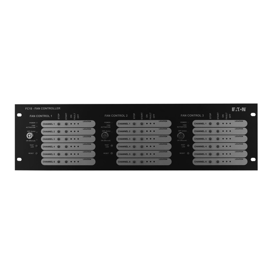
- Page 1 FC18 Fan controller user manual...
-
Page 2: Table Of Contents
5. BASIC SYSTEM LAYOUT ......... 5 5.1. FC18 AND CFC301 ON SAME PANEL AND LOOP ..... -
Page 3: Introduction
FC18 Fan controller user manual 1. Introduction The FC18 Fan Controller can be connected to a Cooper The CFC301 which takes 2 addresses on the loop, • • analogue addressable fire alarm control panel by means one for the control output which appears as a ZMU of the comms Loop utilizing only one address. -
Page 4: Pc Software Operation (Site Installer)
4. Once in the configuration screen Select “Add Master” . Figure 1. Figure 4. 2. Right click Fan Controller icon (Figure 2). Figure 2. Figure 5. Fan controller icon 3. Select “Edit Fan Controller” to go into the configuration screen. Figure 3. FC18 FAN CONTROLLER PR209-166-505-08 January 2018 www.eaton.com... - Page 5 FC18 Fan controller user manual 5. Select the output channel, one to six in the 6. Select in the configuration screen which cause and configuration screen effect is needed for the output to activate. Select the “Enabled” in the configuration screen Figure 7.
-
Page 6: Fan Controller Operation
25s it will result in the “Fault” LED to turn off, the “Off” LED to be turned on and the “On” LED to turn off to show the current status of the fan. FC18 FAN CONTROLLER PR209-166-505-08 January 2018 www.eaton.com... -
Page 7: Basic System Layout
FC18 Fan controller user manual 5. Basic system layout 5.1. FC18 and CFC301 on same 5.3. FC18 and CFC301 on panel and loop di erent networked panels Figure 9. Figure 11. 5.2. FC6 and CFC301 on same panel 5.4. FC6 and MCOM/MCIM on same panel... -
Page 8: Fc18 And Mcom/Mcim On Same Panel But Different Loops
FC18 Fan controller user manual 5.5. FC18 and MCOM/MCIM on same 5.6. FC18 and MCOM/MCIM on di erent panel but di erent loops networked panels Figure 13. Figure 14. FC18 FAN CONTROLLER PR209-166-505-08 January 2018 www.eaton.com... -
Page 9: Fc6 Specification
FC18 Fan controller user manual 6. FC18 6.1. Electrical Loop load Minimum Nominal Maximum Quiescent current 310 A Environmental Operating temperature -10°C +60°C Humidity (Non condensing) 95%rh External 24 volt supply External current 150mA Compatibility Suitable for use with Cooper analogue addressable re systems 6.2. - Page 10 Wheatley Hall Road Doncaster South Yorkshire DN2 4NB United Kingdom © 2017 Eaton All Rights Reserved Printed in UK Eaton is a registered trademark. Publication No. PR209-166-505-08 / CSSC-510 Article No. All trademarks are property January 2018 of their respective owners.
Need help?
Do you have a question about the FC18 and is the answer not in the manual?
Questions and answers