Page 1
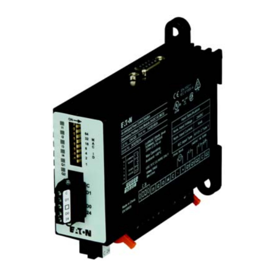
C441 PROFIBUS Module (C441Q, C441S, C441QS, C441SS) User Manual Effective July 2015 New Information C441Q & C441S C441QS & C441SS...
Page 2
OBLIGATION OF EATON. THE CONTENTS OF THIS DOCUMENT SHALL NOT BECOME PART OF OR MODIFY ANY CONTRACT BETWEEN THE PARTIES. In no event will Eaton be responsible to the purchaser or user in contract, in tort (including negligence), strict liability or otherwise for any special, indirect, incidental or consequential...
Page 3
C441 PROFIBUS Module User Manual Support Services The goal of Eaton is to ensure your greatest possible satisfaction with the operation of our products. We are dedicated to providing fast, friendly, and accurate assistance. That is why we offer you so many ways to get the support you need. Whether it’s by phone, fax, or email, you can access Eaton’s support information 24 hours a day, seven days a week.
Always work with another person in case an emergency occurs. Disconnect power before checking controllers performing maintenance. Be sure equipment is properly grounded. Wear safety glasses whenever working on electronic controllers or rotating machinery. C441 PROFIBUS Module User Manual MN042002EN—July 2015 www.eaton.com...
Magnetic Field (IEC61000-4-8) Current Draw (Maximum) 30 mA Voltage Dips (IEC61000-4-11) Protection Degree (IEC60947-1) IP20 Table 8. Input Power Supply Requirements Electrical/EMC Rating Voltage Range 18–30 Vdc Current Draw (Maximum) 30 mA C441 PROFIBUS Module User Manual MN042002EN—July 2015 www.eaton.com...
Current Sinking to the module. On State Voltage 15–30 Vdc Steady State Current Max 15 mA Off State Voltage 0–5 Vdc 24 Vdc source current limit 50 mA Isolation Voltage 250 Vac C441 PROFIBUS Module User Manual MN042002EN—July 2015 www.eaton.com...
Note: For S611 Soft Starter applications, it is recommended to mount a C441QS or C441SS module beside the S611 and wire the D0/D1 terminals between the two devices. More information on this is provided later in this document. C441 PROFIBUS Module User Manual MN042002EN—July 2015 www.eaton.com...
Mounting and Dimensions Dimensions Figure 2. C441Q and C441S Product Dimensions (Attached to C441 Base Unit) C441 PROFIBUS Module User Manual MN042002EN—July 2015 www.eaton.com...
The modules are designed to be installed on the DIN rail or panel surface by screw. Screw fixing dimensions reference below. Figure 3. Mounting of Stand-Alone Model DIN rail width is 35 mm. C441 PROFIBUS Module User Manual MN042002EN—July 2015 www.eaton.com...
A PROFIBUS address setting of 0 will result in the C441 using the default Station Address of 125. Any PROFIBUS Station Address setting greater than 125 will result in the C441 using the default Station Address of 125. C441 PROFIBUS Module User Manual MN042002EN—July 2015 www.eaton.com...
5 (24 Vdc input supply common to input common). See example wiring diagram above. Any device using the provided 24 Vdc input supply must have 500 V isolation from ground. Example devices include pushbuttons and auxiliary contacts. C441 PROFIBUS Module User Manual MN042002EN—July 2015 www.eaton.com...
OV and 24 24 Vdc - Connect isolated power source between C and inputs To C440, S611 Pin 1 or S811+ 24 Vdc – 24 Vdc I/O power AC/DC AC/DC Pin 12 C441 PROFIBUS Module User Manual MN042002EN—July 2015 www.eaton.com...
Connect the C441 PROFIBUS module to the new device or use it as a stand-alone I/O module. When it is powered up again, it will begin working with the new device or as a stand-alone I/O module. C441 PROFIBUS Module User Manual MN042002EN—July 2015 www.eaton.com...
If the “Enable Device Parameterization” parameter is set to “Ignore” (0), device parameters are “ignored” by the C441 PROFIBUS adapter and are not downloaded into the connected device. C441 PROFIBUS Module User Manual MN042002EN—July 2015 www.eaton.com...
0 = Ignore user data 1 = Download Device Parameters Com Adapter Outputs Com Loss Behavior Adapter 0 = Fail Safe (Off) 1 = Hold Last State C440 Com Loss Behavior C440 Fault/Hold Last State C441 PROFIBUS Module User Manual MN042002EN—July 2015 www.eaton.com...
Ramp2 Motor Kick Start Time S811+ 0.0–2.0 sec (in 0.1 sec) Motor Control Terminal Block Local Control Enable S811+ 1 = local control only enabled 0 = disable (terminal block input selects local/network control) C441 PROFIBUS Module User Manual MN042002EN—July 2015 www.eaton.com...
Base Module used. If the IO StandAlone Base is used, only the COM Adapter Outputs_1, Com Adapter Inputs_1 and Com Adapter Status Data Exchange Parameters may be used. C441 PROFIBUS Module User Manual MN042002EN—July 2015 www.eaton.com...
MI Thermal Pile Percentage 0% cold, 100% = overload trip (0–255) input MI Active Fault Queue Last 10 faults input MI Supply Flt-Remaining Rstart Dly Seconds remaining before fault can be reset C441 PROFIBUS Module User Manual MN042002EN—July 2015 www.eaton.com...
Page 34
0x0200 = High Power Trip 0x0400 = Over Voltage Trip 0x0800 = Under Voltage Trip 0x1000 = Voltage Unbalance Trip 0x2000 = Over Current Trip 0x4000 = Low Power Trip 0x8000 = Phase Reversal Trip C441 PROFIBUS Module User Manual MN042002EN—July 2015 www.eaton.com...
Pole Temperature T3 In 0.1 deg C input Pole Temperature Average In 0.1 deg C input Number of Starts Reset Though Command Register input Run Timer Hours, Reset Though Command Register C441 PROFIBUS Module User Manual MN042002EN—July 2015 www.eaton.com...
Page 38
2 = Clear Motor Start Count, 3 = Clear Fault Queue, 255 = Force Overload Rest (TP=0) Note: Command register will clear after write output Configuration Reset 1 = Soft Reset 2 = Factory Defaults C441 PROFIBUS Module User Manual MN042002EN—July 2015 www.eaton.com...
6 = Motor Stall 7 = Motor Jam 8 = OverTemp 9 = UnderLoad 10 = Overload Impending Trip 11 = Reserved 12 = Reserved 13 = Reserved 14 = Reserved 15 = Other C441 PROFIBUS Module User Manual MN042002EN—July 2015 www.eaton.com...
Page 40
Scaled Average current in 0.1 Amps deciamps—Line Input Scaled Three-Phase Currents in L1 RMS current in 0.1 Amps deciamps—Line Input Scaled Average Three-Phase Currents in L2 RMS current in 0.1 Amps deciamps—Line C441 PROFIBUS Module User Manual MN042002EN—July 2015 www.eaton.com...
Page 41
Last 10 Fault/Warning Codes Input Application Status Applications status (present fault) Input Motor Inputs Level Sense Enabled 0x00 = edge sense 0x01 = level sense Input Firmware Version List Input Hardware Version List C441 PROFIBUS Module User Manual MN042002EN—July 2015 www.eaton.com...
Length of User Ext Diagnostic Data 0 = Device Data 0 = Device Data 1 = Adapter Connected; 0 = Adapter Not Connected Reserved 1 = Adapter Married Reserved Reserved Reserved Reserved Reserved C441 PROFIBUS Module User Manual MN042002EN—July 2015 www.eaton.com...
Page 44
1 = Over Voltage Fault 1 = Under Voltage Fault 1 = Voltage Unbalance Fault 1 = Over Current Fault 1 = Low Power Fault 1 = Phase Reversal Fault 40–47 Reserved 48–55 Reserved C441 PROFIBUS Module User Manual MN042002EN—July 2015 www.eaton.com...
Reserved Extended Diagnostic Data 144–151 Reserved Extended Diagnostic Data Table 28. Ext Diag Bit Key Code Bit Sets/Clears Ext diag bit set/ext diag bit clears Ext diag bit clear/ext diag bit clear C441 PROFIBUS Module User Manual MN042002EN—July 2015 www.eaton.com...
Reserved Reserved Reserved Reserved Other Table 31. Ext Diag Bit Key Code Bit Sets/Clears Ext diag bit sets / Ext diag bit clears Ext diag bit clear / Ext diag bit clear C441 PROFIBUS Module User Manual MN042002EN—July 2015 www.eaton.com...
C441Q has 24 Vdc inputs and the C441S has 120 Vac inputs. A GSD file is available for the Motor Insight and it may be downloaded from the Eaton website. The PROFIBUS address is configured using the DIP switches on the C441Q/S modules.
Page 53
Select the CPU under Unspecified CPU 1200. Choose the correct version (V3.0 for this example) and select the ADD button. The following Project View will be displayed, showing a generic CPU. C441 PROFIBUS Module User Manual MN042002EN—July 2015 www.eaton.com...
Page 54
Application Example: Operating a C441 Motor Insight with a Siemens PLC on PROFIBUS-DP Click the CPU box to select it, then select “detect” in the yellow area below it. The Hardware Detection screen will be displayed as follows: C441 PROFIBUS Module User Manual MN042002EN—July 2015 www.eaton.com...
Page 55
Use the standard PROFIBUS connectors and turn on the termination on one or both ends. Refer to the C441 Motor Insight User Manual (publication MN04209001E) for details on the PROFIBUS cable connector pinouts if needed. C441 PROFIBUS Module User Manual MN042002EN—July 2015 www.eaton.com...
Page 56
Then in the Simatic software, select the Options drop down menu and choose: “Install general station description file (gsd)”. Download the GSD file from the Eaton website for the C441Q/S modules, then search for it on your hard drive by selecting the ellipses in the upper right hand...
Page 57
The PLC will be displayed. In the Catalog at the far right, select the arrow next to “Other field devices”, then next to PROFIBUS DP / I/O / Eaton Corp / C441 PROFIBUS Adapter / C441 PROFIBUS ADAPTER / C441 PROFIBUS ADAPTER. Drag and drop the device called C441 PROFIBUS ADAPTER below the category C441 PROFIBUS ADAPTER and drop it below the controller/PROFIBUS master on the Network View screen.
Page 58
Application Example: Operating a C441 Motor Insight with a Siemens PLC on PROFIBUS-DP The following should now be displayed: C441 PROFIBUS Module User Manual MN042002EN—July 2015 www.eaton.com...
Page 59
Application Example: Operating a C441 Motor Insight with a Siemens PLC on PROFIBUS-DP The PROFIBUS network has been created in the offline project. Double click the Slave_1 C441 PROFIBUS module and the following will be displayed: C441 PROFIBUS Module User Manual MN042002EN—July 2015 www.eaton.com...
Page 60
The default base is “IO StandAlone Base”. To use this module with a C441 Motor Insight, select the row with IO StandAlone Base_1 under the Device Overview tab and press the delete key, then confirm you want to delete it. C441 PROFIBUS Module User Manual MN042002EN—July 2015 www.eaton.com...
Page 61
Note the I/O addresses assigned to the parameters. These will be added to the PLC Tags area and tag names will be added for these addresses. The tag names can then be used in the PLC program to control and monitor the Motor Insight and the C441Q/S module’s I/O. C441 PROFIBUS Module User Manual MN042002EN—July 2015 www.eaton.com...
C441 device on the network during the initial startup. These Device-Specific Parameters are a complete list of all configuration parameters for the C441 Motor Insight. C441 PROFIBUS Module User Manual MN042002EN—July 2015 www.eaton.com...
The I/O addresses for the parameters selected for the C441 Motor Insight are shown below for this example: In the Project Tree shown below, select the arrow to the left of PLC Tags to reveal the categories below it. C441 PROFIBUS Module User Manual MN042002EN—July 2015 www.eaton.com...
Page 64
Double click in the top row under the Address column and begin entering the I/O addresses for the C441 Motor Insight as shown below: Note that the software puts % in front of these addresses. There is no need to enter it when entering the addresses. C441 PROFIBUS Module User Manual MN042002EN—July 2015 www.eaton.com...
Page 65
The tag names should fit the application. The tag names used above are just an example. Next, double click “Add new watch table” under “Watch and Force tables” in the Project Tree on the left per the following: C441 PROFIBUS Module User Manual MN042002EN—July 2015 www.eaton.com...
Page 66
This watch table will allow testing the C441 Motor Insight over PROFIBUS without writing a program. This will allow monitoring the input data from the C441 Motor Insight, while operating the C441Q/S outputs. C441 PROFIBUS Module User Manual MN042002EN—July 2015 www.eaton.com...
Download button on the tool bar. Shown below are, from left to right: Compile button, download button and the upload button. As you hover over each of these buttons in the software, it will display its function. C441 PROFIBUS Module User Manual MN042002EN—July 2015 www.eaton.com...
Page 68
Application Example: Operating a C441 Motor Insight with a Siemens PLC on PROFIBUS-DP The results of the compile process will be displayed in the area below the PLC as follows: C441 PROFIBUS Module User Manual MN042002EN—July 2015 www.eaton.com...
Page 69
Next, select the download button to download the project to the PLC. The following window will be displayed. If the controller was in the Run mode, it must be stopped for the download. Select “Stop all” per the following, then select the Load button. C441 PROFIBUS Module User Manual MN042002EN—July 2015 www.eaton.com...
Page 70
The results of the Load will be displayed in the lower portion of the project screen as shown below. “Start all” should be selected, then select the Finish button. This will complete the download and place the PLC into the Run mode per the following: C441 PROFIBUS Module User Manual MN042002EN—July 2015 www.eaton.com...
Page 71
Application Example: Operating a C441 Motor Insight with a Siemens PLC on PROFIBUS-DP With the PLC selected, select “Go online” from the Tool Bar to go online with the project running in the PLC. When online, the Simatic software should look like the following: C441 PROFIBUS Module User Manual MN042002EN—July 2015 www.eaton.com...
Page 72
Below is the Tool Bar located above the Watch List. If the second icon from the right is selected, the Watch List will begin monitoring and displaying the I/O data as follows: C441 PROFIBUS Module User Manual MN042002EN—July 2015 www.eaton.com...
Additional Help In the US or Canada: please contact the Technical Resource Center at 1-877-ETN-CARE or 1-877-326-2273 option 2, option 6. All other supporting documentation is located on the Eaton website at www.eaton.com/Drives C441 PROFIBUS Module User Manual MN042002EN—July 2015 www.eaton.com...
Page 74
Application Example: Operating a C441 Motor Insight with a Siemens PLC on PROFIBUS-DP C441 PROFIBUS Module User Manual MN042002EN—July 2015 www.eaton.com...
Page 75
Application Example: Operating a C441 Motor Insight with a Siemens PLC on PROFIBUS-DP C441 PROFIBUS Module User Manual MN042002EN—July 2015 www.eaton.com...
Page 76
Eaton is dedicated to ensuring that reliable, efficient and safe power is available when it’s needed most. With unparalleled knowledge of electrical power management across industries, experts at Eaton deliver customized, integrated solutions to solve our customers’ most critical challenges.