Advertisement
Quick Links
Пример коэфф TA как 200 ( 1000
/ 5).
Example of CT ratio set to 200
( 1000 / 5).
Пример установки коэфф TV как
150 (15000 / 100).
Example of VT ratio set to 150
(15000 / 100).
Пример установки времени
усреднения мощности 15 мин.
Example of power integration time
set to 15 minutes.
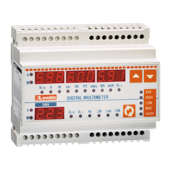
ЦИФРОВЫЕ МУЛЬТИМЕТРЫ
DMK 60 – DMK 61 – DMK 62
ВЕРСИИ
Базовая версия DMK60.
Версия DMK61 с цифровыми выходами.
Версия DMK62 с цифровыми выходами и
интерфейсами RS-485 с протоколом Modbus
RTU.
ОПИСАНИЕ
Крепление на рейку 6 модулей.
4 экрана LED для оптимального показа.
Простая установка и настройка
Измерение по True RMS.
245 измерения с функций анализа мощности
(измерение гармоник до 22^ тока и напряжения).
Запись максимальных и минимальных
значений.
Измерение потребления энергии и генерации (4
квадранта).
УСТАНОВКА ПАРАМЕТРОВ
Для установки параметров нажмите кнопки C и
D одновременно в течение 5 сек.
DISPLAY 1 покажет P.01 это означает что
выбран параметр 01.
DISPLAY 2 и 3 покажут величины выбранных
параметров.
Кнопками A и B увеличьте/уменьшите величину
выбранных параметров.
Используя кнопки C и D, выберите параметры
от P.01 до P.07. Для DMK61 и 62 параметры
превышают P.07 (см дополнение)
Для сохранения и выхода из установки нажмите
кнопку D в течение 2 секунд.
Обычно для программирования достаточно
установки параметра P.01, остальные – по
умолчанию.
ТАБЛИЦА ПАРАМЕТРОВ
ПАР Функция
P.01 Коэфф TA
P.02 Коэфф TV
P.03 Макс время
усреднения
мощности
P.04 Фильтр усред
P.05 Тип системы
1 фаза
2 фазы
3 фазы
3 фазы баланс
P.06 Частота
Авт- 50 – 60
P.07 Анализ гармоник
Примечание! Система подсчета DMK может
подсчитывать величины до 999MVA .
При установке параметров P.01 и P.02
используются оба экрана DISPLAY 2 и 3 для
отображения 5 + 1 после запятой, цифры.
Параметр P.03 используется для установки
времени усреднения максимального потребления
тока и мощности.
P.04 позволяет изменять эффект
стабилизации функции усреднения измерений.
P.05 должен соответствовать схеме
подключения (см. Схемы присоединения').
Необходимо присоединить только один TA к фазе
L1 для трехфазной сбалансированной системы.
Все измерения фаз L2 и L3 за исключением
напряжения, эквивалентны фазы L1.
Установив частоту 50 или 60Hz и OFF анализа
гармоник, увеличивается частота считывания
параметров сети мультиметром. См таблицу
характеристик.
DIGITAL MULTIMETER
VERSIONS
Basic version DMK60.
Version DMK61 with programmable digital outputs
Version DMK62 with programmable digital outputs
and RS-485 interface with Modbus RTU protocol
DESCRIPTION
Modular DIN housing (6 modules)
4 LED displays for optimal viewing
Easy installation and configuration
True RMS measurement
245 readings with power analyzer functions
(harmonic measurement up to 22
voltage and current)
Maximum and minimum values recording
Measurement of power consumption and generation
(four quadrants)
PARAMETERS SETUP
To enter parameter setup, press keys C and D
together for 5 seconds.
DISPLAY 1 will show P.01 indicating that parameter
number 01 is selected.
DISPLAYS 2 and 3 will show the value of the selected
parameter.
A and B keys respectively increase and decrease the
value of the selected parameter.
Use C and D keys to select the parameter from P.01
to P.07. For DMK61 and 62 the parameters go beyond
P.07 (see the addendum enclosed with theinstruments).
To store parameters and exit setup press key D for
two seconds.
Normally, to consent the instrument to operate it is
necessary to set P.01 only, leaving the other
parameters at default factory setting.
Пределы
Умолч
PARAMETER TABLE
PAR Function
1.0 ÷ 2000
1.0
P.01 CT ratio
1.0 ÷ 5000
1.0
P.02 VT ratio
1 ÷ 60мин
15мин
P.03 Max power
2 ÷ 50
10
P.04 Average filter
3ph
P.05 Wiring system
Авт
P.06 Frequency
Вык - Вкл
Вкл
P.07 Harmonic
Note! The calculation system of the DMK can handle
power value up to 999MVA.
To set the value of parameters P.01 and P.02,
DISPLAYS 2 and 3 are used together to show a 5 + 1
decimal digit value.
Parameter P.03 adjusts the time window width for the
integration of current and power maximum demand
P.04 allows to modify the stabilising effect that the
Average function applies to all readings.
P.05 must match the multimeter wiring (see 'Wiring
diagrams section)
It is essential to connect only one CT to L1 phase for a
three-phase balanced connection.
All the measurements of L2 and L3 phases, except for
the voltage values, are equal to those of L1.
The fixed frequency (50 or 60Hz) and the "Off"
harmonic analysis settings improve the multimeter
sampling rate. See the technical characteristics table.
order on both
nd
Range
1.0 - 2000
1.0 - 5000
1 - 60min
integration time
2 - 50
1 phase
2 phases
3 phases
3 phases balanced
Aut - 50 – 60
Off - On
analysis
Default
1.0
1.0
15min
10
3ph
Aut
On
1
Advertisement

Related Manuals for LOVATO ELECTRIC DMK 60


Summary of Contents for LOVATO ELECTRIC DMK 60
- Page 1 ЦИФРОВЫЕ МУЛЬТИМЕТРЫ DIGITAL MULTIMETER DMK 60 – DMK 61 – DMK 62 ВЕРСИИ VERSIONS Базовая версия DMK60. Basic version DMK60. Версия DMK61 с цифровыми выходами. Version DMK61 with programmable digital outputs Версия DMK62 с цифровыми выходами и...
- Page 2 ЧТЕНИЕ ДАННЫХ READINGS DISPLAY Функции кнопок A и B A and B keys functions Кнопками A и B возможен выбор измерений на By means of keys A and B, the measures, indicated экране группы LED 01. by LED group 01, can be selected. ...
- Page 3 Функции кнопки C C key functions Кнопка C активирует функции сгруппированные The C key individually activates the functions grouped под экраном LED 03, возможна деактивация всех under LED 03. It is possible to leave all the functions функций. Функция усреднения Avg может disabled.
-
Page 4: Wiring Diagrams
СХЕМЫ ПРИСОЕДИНЕНИЯ ВНИМАНИЕ! Для присоединения СT, смотрите рекомендации ниже. WIRING DIAGRAMS IMPORTANT!! For CT connections, see recommendations at the bottom of the page. 100...240VAC 100...240VAC 100...240VAC 34 36 17 18 36 13 32 34 13 14 S1 S2 S1 S2 L1 L2 L3 S1 S2 -- -... - Page 5 ГЕОМЕТРИЧЕСКОЕ ПРЕДСТАВЛЕНИЕ АКТИВНОЙ И РЕАКТИВНОЙ GEOMETRIC REPRESENTATION OF ACTIVE AND REACTIVE POWER МОЩНОСТЕЙ Legend Exported active power Обозначения Отдаваемая активная мощность Imported active power Потребляемая активная мощность Imported reactive power Потребляемая реактивная мощность Exported reactive power Отдаваемая реактивная мощность Note: Примечание: ...
- Page 6 Словарь Vi = Величины напряжения при волновом цикле. Glossary Vi = Voltage values acquired in waveform cycle. Ai = Величины тока при волновом цикле. Ai = Current value acquired in waveform cycle.
-
Page 7: Технические Характеристики
ТЕХНИЧЕСКИЕ ХАРАКТЕРИСТИКИ TECHNICAL CHARACTERISTICS Питание Auxiliary supply Номинальное 100 240VAC Rated voltage Us 100 - 240VAC напряжение Us 110 - 250VDC 110 250VDC Operating limits 85 - 265VAC Рабочие пределы 85 265VAC 93.5 - 300VDC 93,5 300VDC Frequency 45 - 450Hz Частота... - Page 8 Protection degree IP41 frontal IP20 клеммы избежание несчастных случаев и аварий. IP20 housing and Прибор может быть модифицирован Вес DMK 60 0,29kg terminals bloks производителем без предварительного DMK 61 0,30kg уведомления.. Технические данные и Weight DMK 60 0.29kg DMK 62 0,32kg описания...
Need help?
Do you have a question about the DMK 60 and is the answer not in the manual?
Questions and answers