LOVATO ELECTRIC DMG600 Instruction Manual
Hide thumbs
Also See for DMG600:
- Instruction manual (20 pages) ,
- Installation manual (9 pages) ,
- Installation manual (7 pages)
Table of Contents
Advertisement
ADVERTENCIA
● Leer atentamente el manual antes de instalar y utilizar el multímetro.
● Este dispositivo debe ser instalado por personal cualificado conforme a
la normativa de instalación vigente a fin de evitar daños personales o
materiales.
● Antes de realizar cualquier operación en el dispositivo, desconectar la corriente de las
entradas de alimentación y medida y cortocircuitar los transformadores de corriente.
● El fabricante no se responsabilizará de la seguridad eléctrica en caso de que el dispositivo no
se utilice de forma adecuada.
● Los productos descritos en este documento se pueden actualizar o modificar en cualquier
momento. Por consiguiente, las descripciones y los datos técnicos aquí contenidos no tienen
valor contractual.
● La instalación eléctrica del edificio debe disponer de un interruptor o disyuntor. Este debe
encontrarse cerca del dispositivo, en un lugar al que el usuario pueda acceder con facilidad.
Además, debe estar identificado como tal (IEC/EN 61010-1 § 6.11.2).
● Limpiar el dispositivo con un trapo suave; no utilizar productos abrasivos, detergentes líquidos
o disolventes.
Índice
Introducción
Los multímetros DMG600 y DMG610 están diseñados para ofrecer
máxima facilidad de uso con una gran variedad de funciones avanzadas.
Realizados para montarse en panel con tamaño estándar de 96x96 mm,
combinan el moderno diseño del frontal con una instalación práctica y la
posibilidad de expansión por la parte trasera, en la que se puede alojar un
módulo de expansión (EXP). El frontal dispone de la interface óptica de
infrarrojos que permite realizar la programación por USB o WiFi.
La pantalla LCD retroiluminada proporciona una interface de usuario clara
e intuitiva. Además, el modelo DMG610 dispone de una interface de
comunicación RS485 aislada con protocolo Modbus para permitir la
supervisión.
Doc: I411EGB04_15.doc
ES
DMG600 - DMG610
Multímetro digital
MANUAL DE INSTRUCCIONES
Página
1
2
2
2
3
4
5
5
5
6
6
6
7
7
8
8
8
13
14
14
15
15
16
17
18
19
19
20
DMG600 - DMG610
Digital multimeter
INSTRUCTIONS MANUAL
WARNING!
Carefully read the manual before the installation or use.
This equipment is to be installed by qualified personnel, complying to
current standards, to avoid damages or safety hazards.
● Before any maintenance operation on the device, remove all the voltages from measuring
and supply inputs and short-circuit the CT input terminals.
● Products illustrated herein are subject to alteration and changes without prior notice.
● Technical data and descriptions in the documentation are accurate, to the best of our
knowledge, but no liabilities for errors, omissions or contingencies arising there from are
accepted.
● A circuit breaker must be included in the electrical installation of the building. It must be
installed close by the equipment and within easy reach of the operator.
It must be marked as the disconnecting device of the equipment:
IEC /EN 61010-1 § 6.11.2.
● Clean the instrument with a soft dry cloth; do not use abrasives, liquid detergents or solvents
Index
Introduction
The DMG600 and DMG610 multimeters have been designed to combine
the maximum possible easiness of operation together with a wide choice
of advanced functions. The flush-mount 96x96mm housing joins the
modern design of the front panel with the tool-less mounting of the device
body and the expansion capability of the rear panel, where it is possible to
mount plug-in one module of EXP... series. The front panel is equipped
with an infrared optical interface that allows programming through USB or
WiFi dongles. The backlighted LCD display offers a user-friendly interface.
Model DMG610 is also provided with a isolated RS-485 interface with
Modbus protocol to consent remote supervision.
21/04/2015
.
Page
1
2
2
2
3
4
5
5
5
6
6
6
7
7
8
8
8
13
14
14
15
15
16
17
18
19
19
20
p. 1 / 20
Advertisement
Table of Contents

Related Manuals for LOVATO ELECTRIC DMG600


Summary of Contents for LOVATO ELECTRIC DMG600
-
Page 1: Table Of Contents
Introduction Los multímetros DMG600 y DMG610 están diseñados para ofrecer The DMG600 and DMG610 multimeters have been designed to combine máxima facilidad de uso con una gran variedad de funciones avanzadas. the maximum possible easiness of operation together with a wide choice Realizados para montarse en panel con tamaño estándar de 96x96 mm,... -
Page 2: Descripción
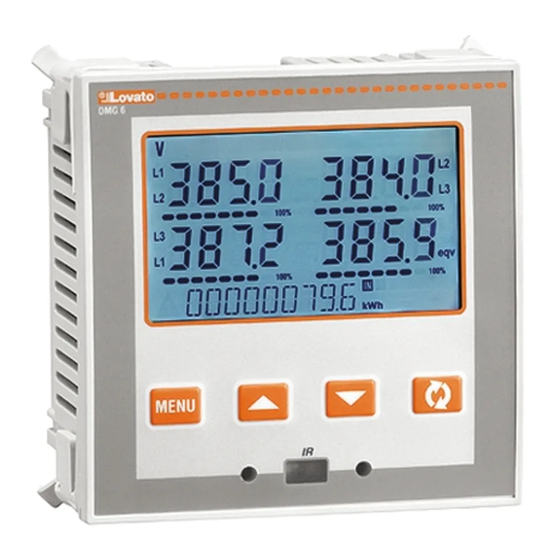
Backlit LCD screen. Versiones: Versions: DMG600, versión básica, ampliable DMG600 – base version, expandable. DMG610, ampliable con interface RS485 incorporada DMG610 – expandable, with built-in RS485 interface. 4 teclas de desplazamiento para funciones y configuración 4 navigation keys for function and settings. -
Page 3: Visualización De Medidas
Visualización de medidas Viewing of measurements Las teclas ▲ y ▼ permiten recorrer una a una las páginas de The ▲and ▼keys allow to scroll the pages of viewed measurements visualización de medidas. La página actual se identifica mediante la one by one. -
Page 4: Tabla De Páginas De La Pantalla
Tabla de páginas de la pantalla Table of display pages Selección con ▲ y ▼ Selección con Selection with ▲and ▼ Selection with SUBPÁGINA Nº PÁGINAS PAGES SUB-PAGES TENSIÓN ENTRE FASES PHASE-TO-PHASE VOLTAGES V(L1-L2), V(L2-L3), V(L3-L1), V(LL)EQV V(L1-L2), V(L2-L3), V(L3-L1), V(LL)EQV TENSIÓN DE FASE PHASE-TO-NEUTRAL VOLTAGES V(L1-N), V(L2-N), V(L3-N), V(L-N)EQV... -
Page 5: Desplazamiento Por Las Páginas De La Pantalla
Indication of hour meter Si está activado (ver el menú P05), en el multímetro DMG600-610 If the hour meter is enabled (see menu P05) the DMG600-610 displays aparece la página del contador horario con el formato indicado en la... -
Page 6: Indicación Del Estado De Los Límites (Limn)
Indicación análisis armónico Harmonic analysis indication El DMG600-610 permite realizar el análisis armónico de hasta 15° orden The DMG600-610 features harmonic analysis up to the 15th order for de las siguientes medidas: the following measurements: ... -
Page 7: Puerto De Programación Ir
Puerto de programación IR IR programming port Los parámetros del DMG600-610 se pueden configurar por medio del The parameters of the DMG600-610 can be configured through the puerto óptico frontal mediante el uso de la llave de programación IR- front optical port, using the IR-USB code CX01 programming dongle, USB con código CX01 o la llave IR-WiFi con código CX02. -
Page 8: Menú Principal
Menú principal Main menu Para acceder al menú principal: To access the main menu: Pulsar la tecla MENU. Se mostrará el menú principal (ver figura) con Press the MENU button. The main menu is displayed (see figure) with las opciones disponibles: the following possible choices: o SET: acceso al menú... - Page 9 DMG600-610. This data can be restored when necessary in the work En la memoria EEPROM del DMG600-610 se puede guardar una copia memory. The data backup 'copy' and 'restore' commands can be found de seguridad (backup) de los datos de configuración que se pueden...
- Page 10 Tabla de parámetros Parameter table A continuación se describen en forma de tabla todos los parámetros de Below are listed all the programming parameters in tabular form. For each programación disponibles. Además de indicar el rango de configuración y parameter are indicated the possible setting range and factory default, as la configuración de fábrica de cada parámetro, se explica la función del well as a brief explanation of the function of the parameter.
- Page 11 P03 – CONTRASEÑA Defecto Rango P03.01 Uso de contraseña OFF-ON P03 – PASSWORD Default Range P03.02 Contraseña de usuario 1000 0-9999 P03.01 Enable passwords OFF-ON P03.03 Contraseña de nivel 2000 0-9999 P03.02 User level password 1000 0-9999 avanzado P03.03 Advanced level password 2000 0-9999 P03.01: cuando se configura en OFF, la gestión de contraseñas se desactiva y se...
- Page 12 Modbus RTU Modbus RTU P07.n.05 Protocolo P07.n.04 Stop bits Modbus ASCII P07.n.05 Protocol Modbus RTU Modbus RTU Modbus TCP Modbus ASCII 000.000.000. 000.000.000.000 - P07.n.06 Dirección IP Modbus TCP 255.255.255.255 P07.n.06 IP Address 000.000.000. 000.000.000.000 - 000.000.000. 000.000.000.000 - P07.n.07 Máscara de subred 255.255.255.255 255.255.255.255 1001...
-
Page 13: Alarmas
P11 – IMPULSOS Defecto Rango P11 – PULSES Default Range (PULn, n=1..2) (PULn, n=1..2) P11.n.01 Medida original OFF, kWh+, kWh-, P11.n.01 Source measurement OFF, kWh+, kWh-, kVArh+, kVArh-, kVAh kvarh+, kvarh-, kVAh P11.n.02 Unidad de medida 10/100/1 k/10 k P11.n.02 Count unit 10/100/1k/10k P11.n.03 Duración de impulso 0.01-1.00... -
Page 14: Menú De Comandos
Menú de comandos Commands menu El menú de comandos sirve para realizar operaciones esporádicas, The commands menu allows executing some occasional operations like como poner a cero medidas, contadores, alarmas, etc. reading peaks resetting, counters clearing, alarm reset, etc. ... -
Page 15: Uso De La Llave Cx01
Press 3 times consecutively and fast the dongle button. segundos. At this point the display of the DMG600-610 shows the first of the 6 possible Esperar hasta que el LED LINK se vuelva naranja y empiece a commands (D1…D6). -
Page 16: Instalación
Instalación Installation La unidad DMG600-610 está diseñada para montarse empotrada. DMG600-610 is designed for flush-mount installation. With proper mounting, it Cuando está correctamente montada, ofrece protección delantera IP54. guarantees IP54 front protection. Desde el interior del panel, situar cada una de las cuatro mordazas de ... -
Page 17: Esquemas De Conexión
Esquemas de conexión Wiring diagrams Conexión trifásica con o sin neutro Conexión bifásica 3-phase connection with or without neutral 2-phase connection P01.07 = L1-L2-L3-N L1-L2-L3 P01.07 = L1-N-L2 Conexión monofásica Conexión trifásica equilibrada con o sin neutro Single-phase connection Balanced 3-phase connection with or without neutral P01.07 = L1-N P01.07 = L1-L2-L3-N-BIL L1-L2-L3-BIL Conexión ARON trifásica sin neutro... -
Page 18: Disposición De Los Terminales
TRANSMISIÓN, alimentación de 220 a 240 V CA, 10% o de 110 a 120 V CA a solicitud RS-232/RS-485 opto-isolated converter drive, 38,400 Baud-rate max, automatic or manual TRANSMIT line supervision, 220…240VAC 10% supply (possible 110…120VAC on request). Disposición de los terminales Terminals position DMG600 DMG610 Doc: I411EGB04_15.doc 21/04/2015 p. 18 / 20... -
Page 19: Dimensiones Mecánicas Y Escotadura Del Panel (Mm)
Dimensiones mecánicas y escotadura del panel (mm) Mechanical dimensions and front panel cutout (mm) Características técnicas Technical characteristics Alimentación Supply Tensión nominal Us 100 - 440 V~ Rated voltage Us 100 - 440V~ 110 - 250 V= 110 - 250V= Límites de funcionamiento 90 - 484 V~ Operating voltage range... -
Page 20: Historial De Revisiones Del Manual
Certificaciones y conformidad Certifications and compliance cULus En trámite cULus Pending Normas IEC/EN 61010-1, IEC/EN 61000-6-2 Reference standards IEC/EN 61010-1, IEC/EN 61000-6-2 IEC/EN 61000-6-4 IEC/ EN 61000-6-4 UL61010-1 y CSA C22.2-N°61010-1 UL61010-1 and CSA C22.2-N°61010-1 Alimentación auxiliar conectada a una red con tensión fase-neutro ≤300 V ...
Need help?
Do you have a question about the DMG600 and is the answer not in the manual?
Questions and answers