Advertisement
Quick Links
(P.11-P.21)
HIGH
LOW
t = P.17-P.27
t = P.18-P.28
K*
(zob.P.11 do P.18 i P.21 do P.28)
(P.11-P.21)
HIGH
LOW
t = P.17-P.27
t = P.18-P.28
K*
(zob.P.11 do P.18 i P.21 do P.28)
PL
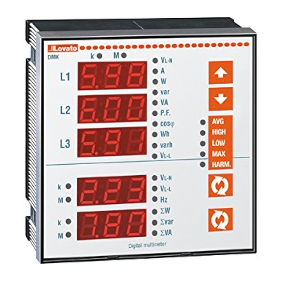
MIERNIK CYFROWY
DMK 31 i DMK 61 z wyjściami cyfrowymi
DMK 32 i DMK 62 z wyjściami cyfrowymi
i szeregowym interfejsem RS-485
DODATEK
WPROWADZENIE
Jest to instrukcja obsługi mierników DMK
z programowalnymi cyfrowymi wyjściami
i interfejsem RS-485.
Charakterystyka techniczna wyjść cyfrowych
jest wyspecyfikowana w tej instrukcji.
WYJŚCIA CYFROWE
- 2 programowalne wyjścia cyfrowe, jedno
z przekaźnikiem półprzewodnikowym (wyjście
1 – SSR) i jedno ze stykiem przełącznym (wyjście 2).
- Funkcje dostępne: minimalny próg z histerezą,
maksymalny próg z histerezą, minimalny
i maksymalny próg.
- Programowalne opóźnienie na maksymalnym
i minimalnym progu.
- Możliwość wyboru stanu niezadziałania przekaźnika
- Programowalna blokada wzbudzonego przekaźnika.
- Funkcja pomiaru energii.
PROGRAMOWANIE
Każde wyjście cyfrowe może być przydzielone
do jednego z pomiarów dostępnego w urządzeniu.
Dwa progi, które będą definiować punkt wzbudzenia
mogą być później zastosowane do pomiaru. Kryteria
działania zależą od wybranej funkcji spośród
czterech dostępnych, które będą wyjaśnione poniżej.
Wszystkie ustawienia wykonuje się przez nastawy
specyficznych parametrów.
FUNKCJA PROGU MINIMALNEGO
W funkcji minimalnego progu Próg Niski (Low) określa punkt
wzbudzenia podczas gdy Próg Wysoki (High) określa
kasowanie. Wyjście zostaje wzbudzone, gdy wybrany
pomiar jest niższy niż Próg Niski (Low) przez czas
zaprogramowanego opóźnienia. Kiedy wartość pomiaru
przekroczy punkt Najwyższy (High) to po upływie opóźnienia
stan wyjścia zostanie skasowany. Jeżeli aktywna jest
blokada stanu wyjścia to kasowanie można wykonać tylko
ręcznie. Naciśnięcie przycisków A i B jednocześnie
spowoduje pokazanie na wyświetlaczach 1 i 2 stanu
wzbudzenia wyjść 1 i 2. W tym momencie blokady wyjść
t
mogą być kasowane przez naciśnięcie przycisku A przez
2 sekundy. Aby dojść do poprzedniego menu należy
Przek. wzb.
nacisnąć przycisk B. Wzbudzenie wyjścia oznacza albo
Przek. nie wzb.
energetyzację lub deenergetyzację przekaźnika zależnie
od ustawienia „stanu niezadziałania przekaźnika".
FUNKCJA PROGU MAKSYMALNEGO
W funkcji maksymalnego progu Próg Wysoki (High) określa
punkt wzbudzenia podczas gdy Próg Niski (Low) określa
kasowanie. Wyjście zostaje wzbudzone, gdy wybrany pomiar
jest większy niż Próg Wysoki (High) przez czas
zaprogramowanego opóźnienia. Kiedy wartość pomiaru
obniży się poniżej punktu Low to po upływie opóźnienia stan
wyjścia zostanie skasowany. Jeżeli aktywna jest blokada
stanu wyjścia to kasowanie można wykonać tylko ręcznie.
Naciśnięcie przycisków A i B jednocześnie spowoduje
pokazanie na wyświetlaczach 1 i 2 stanu wzbudzenia wyjść 1
i 2. W tym momencie blokady wyjść mogą być kasowane
t
przez naciśnięcie przycisku A przez 2 sekundy. Aby dojść
do poprzedniego menu należy nacisnąć przycisk B.
Przek. wzb.
Wzbudzenie wyjścia oznacza albo energetyzację lub
Przek. nie wzb.
deenergetyzację przekaźnika zależnie od ustawienia „stanu
niezadziałania przekaźnika.
Dokument Protokoły ModBus do DMK31..32..61..62
DIGITAL MULTIMETER
DMK 31 and DMK 61 with digital outputs
DMK 32 and DMK 62 with digital outputs and
RS-485 serial interface
INTRODUCTION
This is the operative manual addendum for DMK
multimeters with programmable digital outputs and
insulated RS-485 serial interface.
The technical characteristics for digital outputs and
RS-485 interface are specified on the operative
manual.
DIGITAL OUTPUTS
2 programmable digital outputs, one with solid
state relay (SSR – output 1) and one with
changeover contact (output 2).
Available functions: Minimum threshold with
hysteresis, maximum threshold with hysteresis,
maximum and minimum thresholds
Programmable delay on both minimum and
maximum thresholds
Possibility to choose the idle relay status
Programmable relay trip latch
Energy meter function
PROGRAMMING
Each digital output can be assigned to one of the
measures given by the instrument. Two thresholds
that will define the tripping point can then be applied
to the measure. The operating criteria depends on
the function selected among the four available that
will be explained in the sections below.
All the settings are done by the specific setup
parameters.
MINIMUM THRESHOLD FUNCTION
With the minimum threshold function, the Low threshold
defines the trip point, while the High threshold is for the
resetting. The output trips when the selected measure is
less than Low threshold for the programmed delay. When
the measure value becomes higher than the High setpoint,
after the delay, the output status is resetted. If the output
latch is enabled, the reset can only be manually done.
Pressing keys A and B together , displays 2 and 3 will show
the trip status of outputs 1 and 2. At this point, the output
latches can be resetted by pressing key A for 2 sec. To go
back to the previous menu, press key B. Output trip
denotes either energizing or de-energizing of the relay,
depending on 'Idle relay status' setting.
MAXIMUM THRESHOLD FUNCTION
With the maximum threshold function, the High threshold
defines the trip point, while the Low threshold is for the
resetting. The output trips when the selected measure is
more than High threshold for the programmed delay. When
the measure value decreases less than the Low setpoint,
after the delay the output status is resetted. If the output
latch is enabled, the reset can be done only manually.
Pressing keys A and B together , displays 2 and 3 will show
the trip status of outputs 1 and 2. At this point, the output
latches can be resetted by pressing key A for 2 sec. To go
back to the previous menu, press key B. Output trip
denotes either energizing or de-energizing of the relay,
depending on 'Idle relay status' setting.
Str. 1 / 22
Advertisement

Related Manuals for LOVATO ELECTRIC DMK 31


Summary of Contents for LOVATO ELECTRIC DMK 31
- Page 1 MIERNIK CYFROWY DIGITAL MULTIMETER DMK 31 i DMK 61 z wyjściami cyfrowymi DMK 31 and DMK 61 with digital outputs DMK 32 i DMK 62 z wyjściami cyfrowymi DMK 32 and DMK 62 with digital outputs and i szeregowym interfejsem RS-485...
- Page 2 FUNKCJA MAKSIMUM-MINIMUM MAXIMUM-MINIMUM FUNCTION W funkcji minimum-maksimum oba progi określają punkty With the maximum-minimum function, both thresholds are wzbudzenia. Kiedy wartość pomiaru jest niższa niż Low lub for tripping. When the measure value is less than Low or wyższa niż High wtedy po upływie odpowiedniego czasu more than High, then, after the respective delays, the (P.11-P.21) opóźnienia wyjście zostaje wzbudzone.
- Page 3 TABLE 1: TABELA 1 : READINGS ASSOCIABLE TO DIGITAL ODCZYTY ZWIĄZANE Z WYJŚCIAMI CYFROWYMI OUTPUTS ODCZYT READING L1,L2,L3 phase voltage Napięcie fazowe L1, L2, L3 L1-L2, L2-L3,L3-L1 phase-to-phase voltage Napięcie międzyfazowe L1-L2, L2-L3, L3-L1 L1,L2,L3 phase current Prąd fazy L1, L2, L3 L1,L2,L3 active power ...
- Page 4 TABELA 1 (kontynuacja) TABLE 1 (continues) ODCZYT READING Średnia moc bierna L1 Average L1 reactive power Średnia moc bierna L2 Average L2 reactive power Średnia moc bierna L3 Average L3 reactive power Średnia moc pozorna L1 Average L1 apparent power Średnia moc pozorna L2 Average L2 apparent power Średnia moc pozorna L3...
- Page 5 TABLE 1 (continues) TABELA 1 (kontynuacja) ODCZYT READING 14. Harmoniczna napięcia fazowego L1 14. harmonic phase voltage L1 14. Harmoniczna napięcia fazowego L2 14. harmonic phase voltage L2 14. Harmoniczna napięcia fazowego L3 14. harmonic phase voltage L3 15. Harmoniczna napięcia fazowego L1 15.
- Page 6 15. Harmoniczna prądu fazowego L1 15. harmonic phase current L1 15. Harmoniczna prądu fazowego L2 15. harmonic phase current L2 15. Harmoniczna prądu fazowego L3 15. harmonic phase current L3 16. Harmoniczna prądu fazowego L1 16. harmonic phase current L1 16.
- Page 7 SZEREGOWY INTERFEJS RS-485 RS 485 SERIAL INTERFACE Modele DMK32 i DMK62 mają wbudowany izolowany Model DMK32 and DMK 62 have a built-in isolated Half interfejs szeregowy RS-485. duplex RS-485 serial interface. Ustawienia portu komunikacyjnego dokonuje się przez The communication port setting is obtained through zdefiniowanie parametrów w następujący sposób.
-
Page 8: Modbus® Functions
FUNKCJE MODBUS® MODBUS® FUNCTIONS Dostępne funkcje: The available functions are: Pozwala odczytać pomiary Allows to read the multimeter 04 = Read input 04 = Read input miernika measures. register register 06 = Preset single 06 = Preset single Allows to set the setup Pozwala ustawić... -
Page 9: Function 06: Preset Single Register
Odpowiedź Slave: Slave response: Adres slave Slave address Funkcja Function Ilość bajtów Byte number Rejestr MSB 10h MSB register 10h Rejestr LSB 10h LSB register 10h --------------------------------------------------- ---- --------------------------------------------------- ---- Rejestr MSB 17h MSB register 17h Rejestr LSB 17h LSB register 17h MSB CRC MSB CRC LSB CRC... - Page 10 FUNKCJA 07: ODCZYT STATUSU WYJĄTKÓW FUNCTION 07: READ EXCEPTION STATUS Ta funkcja pozwala odczytać status urządzenia. This function allows to read the status of the instrument. Zapytanie Master: Master query: Adres slave Slave address Funkcja Function MSB CRC MSB CRC LSB CRC LSB CRC Poniższa tabela wskazuje znaczenie bitów wysłanych...
- Page 11 Odpowiedź Slave: Slave response: Adres slave Slave address Funkcja Function Numer bajtu Byte number Dane 1 Data 1 Dane 2 Data 2 Dane 3 Data 3 Dane 4 Data 4 MSB CRC MSB CRC LSB CRC LSB CRC Dane 1 reprezentują typ miernika, dane 2 informują Data1 represents the multimeter type while data2 o wersji oprogramowania.
- Page 12 Gdzie: Whereas: 08 = adres “slave”. 08 = slave address 04 = funkcja Modbus® odczytu z lokalizacji. 04 = Modbus® function ‘Read input register’ 00 0F = adres wymaganego rejestru (równa napięciu 00 0F = Address of the required register (equivalent międzyfazowym), zmniejszona o jeden.
- Page 13 Pomiary przesłane przez protokoły wyrażone The measures transferred by the protocol are są w jednostce pomiarowej wskazanej w Tabeli 2, expressed in the unit of measure listed in Table 2, i wszystkie mają długość 4 bitów. and they are all 4 byte long. For power factor, cosφ, active and reactive Dla wartości współczynnika mocy, cosφ...
- Page 14 FUNKCJA 16: USTAWIENIA WIELU REJESTRÓW FUNZIONE 16: PRESET MULTIPLE REGISTER Ta funkcja pozwala modyfikować wiele parametrów This function allows to modify multiple parameters, jedną wiadomością, lub ustawić wartość dłuższą niż with a single message, or to preset a value longer jeden rejestr.
- Page 15 Hex FFFF = CRC OBLICZANIE CRC (SPRAWDZANIE) CRC CALCULATION (CHECKSUM) Przykład obliczenia: Example of CRC calculation: Rama = 0207h Frame = 0207h CRC xor BYTE = CRC Rozpoczęcie CRC 1111 1111 1111 1111 CRC initialization 1111 1111 1111 1111 Ładowanie 1 bajt 0000 0010 Load the first byte 0000 0010...
- Page 16 TABELA 2: TABLE 2: POMIARY DOSTĘPNE PRZEZ PROTOKOŁY KOMUNIKACYJNE MEASURES SUPPLIED BY SERIAL COMMUNICATION PROTOCOL ADRES SŁOWA POMIAR MEASURE JEDN. FORMAT ADDRESS UNIT FORMAT Napięcie fazy L1 L1 Phase voltage Unsigned long Napięcie fazy L2 L2 Phase voltage Unsigned long Napięcie fazy L3 L3 Phase voltage Unsigned long...
- Page 17 TABELA 2 (continua) TABLE 2 (continuation) ADRES SŁOWA POMIAR MEASURE JEDN. FORMAT ADDRESS UNIT FORMAT Średnia moc czynna fazy L1 Average L1 Phase active power Unsigned long Średnia moc czynna fazy L2 Average L2 Phase active power Unsigned long Średnia moc czynna fazy L3 Average L3 Phase active power Unsigned long Średnia moc bierna fazy L1...
- Page 18 TABELA 2 (continua) TABLE 2 (continued) ADRES SŁOWA POMIAR MEASURE JEDNO. FORMAT ADDRESS UNIT FORMAT 7. harmoniczna napięcia fazy L1 7. harmonic on phase voltage L1 Unsigned long 7. harmoniczna napięcia fazy L2 7. harmonic on phase voltage L2 Unsigned long 7.
- Page 19 TABELA 2 (continua) TABLE 2 (continuation) ADRES SŁOWA POMIAR MEASURE JEDN. FORMAT ADDRESS UNIT FORMAT 142h 2. harmoniczna prądu fazy L1 2. harmonic on phase current L1 Unsigned long 144h 2. harmoniczna prądu fazy L2 2. harmonic on phase current L2 Unsigned long 146h 2.
- Page 20 TABELA 2 (continua) TABLE 2 (continuation) ADRES SŁOWA POMIAR MEASURE JEDN. FORMAT ADDRESS UNIT FORMAT 1AEh 20. harmoniczna prądu fazy L1 20. harmonic on phase current L1 Unsigned long 1B0h 20. harmoniczna prądu fazy L2 20. harmonic on phase current L2 Unsigned long 1B2h 20.
- Page 21 kondensatorów Znamionowa częstotliwość 2040h Rated capacitor frequency Unsigned integer kondensatorów 2052h Adres Serial address Unsigned integer 2054h Prędkość przesyłu danych Baud rate Unsigned integer 2056h Polaryzacja Parity Unsigned integer TABELA 4: TABLE 4: KOMENDY COMMANDS ADRES ILOŚĆ KOMENDA COMMAND WARTOŚĆ FORMAT ADDRESS SŁÓW...
- Page 22 Podłączenie PC-DMK.. przez RS485 PC-DMK connection through RS485 interface TR A NC NO C RS485 RS485 RELAY AC-DC RELAY AC-DC DMK32/62 n°31 DMK32/62 n°1 Repeat this wiring diagram up to 255 devices TR A TR A TR A B TR A B SG NO C RS485 RS485...
Need help?
Do you have a question about the DMK 31 and is the answer not in the manual?
Questions and answers