Advertisement
Quick Links
OPERATING
MANUEL
Information in this manual is reviewed and completely reliable. Responsibility is not assumed due to any typing error.
Products in this manual are available only for information purpose and they may be changed without notice.
Models :
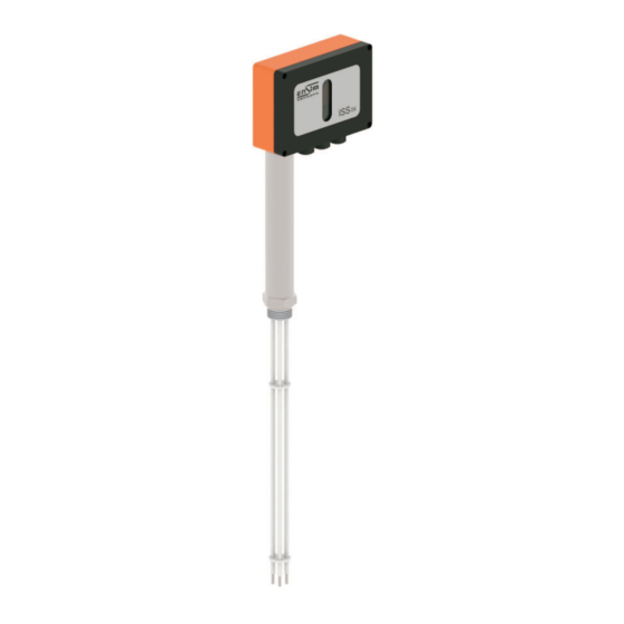
ISS 04
Important Notes:
Used Symbols :
: Caution
Please read this manual carefully before installation of the level switch. User is responsible for accidents and losses arising
from failure to comply with the warnings in this manual.
In the event that level switch is broken, take measures in order to prevent accidents and losses which can occur in its system.
There is not any fuse and circuit breaker on the instrument; they should have been added to the system by the user.
This manual should be stored in an easily accessible place for subsequent use.
The manufacturer's liability cannot exceed the purchase price of the device according to the law.
Do not make any modification on the instrument and do not try to repair it. Reparation should be made by authorized service staff.
Do not operate the system before making assembly in compliance with the assembly chart related to the instrument.
Products which do not contain label and serial number are considered to be excluded from the warranty scope.
The instrument's useful life, determined and announced by the ministry, is 10 years.
Table of Contents :
1.
General Information...........................................................................................................................................................................2
2.
Installation .........................................................................................................................................................................................3
3.
Failure Detection..............................................................................................................................................................................17
4.
Disassembly of Instrument ............................................................................................................................................................17
5.
Service .............................................................................................................................................................................................17
6.
Recalibration....................................................................................................................................................................................17
7.
Repair................................................................................................................................................................................................17
8.
Disposal ...........................................................................................................................................................................................17
9.
Terms of Warranty ..........................................................................................................................................................................17
10.
Terms of Return …………………………………………………………………………………………................................................…17
ýss
Model :
LEVEL SWITCH
: Note
: Disposal
1
Model : Model: 14-2022-001
Advertisement

Related Manuals for ENSIM SENSORS ISS 04


Summary of Contents for ENSIM SENSORS ISS 04
- Page 1 Information in this manual is reviewed and completely reliable. Responsibility is not assumed due to any typing error. Products in this manual are available only for information purpose and they may be changed without notice. Models : ISS 04 Important Notes: Used Symbols :...
-
Page 2: General Information
(It is not used under -5 °C) 1.3. Working Principle ISS 04 Level Sensor is designed for controlling of conductive measurement principle. lt has four different measurement probe and an electronic unit and so without any other control unit it allows to control by itself. -
Page 3: Installation
1.6. Target Group This operating manual has been prepared for qualified technical personel. 1.7. Security Notes Following notes should be taken into consideration in order to avoid dangers which can occur on the operator and around the ambient. Installation, operation and maintenance of this instrument should be made only by people who have read the operating manual and who are knowledgeable about work safety! It should be complied with work safety, accident prevention regulations and national installation standards. - Page 4 Components Figure 1 Terminal Box (E.Card Case) Heat insulating Lag Connection Screw Joint Ring (Copper or Aluminium) Electrode Rods Fixing Nut Electrode Tips Connection Headers S1- Configuration Switch S2- Sensitivity Switch Indicator LEDs Terminal Strip Cable Glands (3xPg11) Fieldbus Add-On Card Connection Header (Option!.) CanOpen Terminal (Option!.) Fieldbus Line Cable Gland (Option!.) Hole for Add-On Card Fixing screw.
- Page 5 Figure 4 Figure 5 ISS 04 can work on boilers with configuration F1 , F2 , F3 and on water strage vessels with configuration F1 and F4 . Working with Boilers 1- If your need is to get signals at some levels of water and you don’t concern boiler security etc then Configuration-I suits your need.
- Page 6 2.5. Dimensions : Figure 6 Seating Surface Kontrol kutusu bakýþ açýsýna uygun olacak þekilde 360 derece döndürülebilir. Note: 33x40mm Joint Ring Mechanical Installation The mounting part of the ISS-04 is the G1” screw. While mounting: *Be careful about the seating surface is clean and flat. *Don’t use any PTFE sealing strip, use joint ring of Cu/Al instead.
- Page 7 2.7. Calculating Electrode Rod Lenghts Once you ve decided the Control mode , calculate the rod lenghts and cut them as mentioned following pages. F1.Level Signaler ISS-04 probe works as a simple “water level signaler” at this mode. You must cut the electrode rods simply “ which level you want a signal at.” Mounting Level Don’t forget : I-To include the mounting bush or flange height (F) to the desired rod length.
- Page 8 F3.Fill Control + 2 pcs Low Level Alarm The electrod tips 1..4 act as Low Level1, Low Level2, Pump-ON, Pump-OFF respectively. The lengths of two low level electrodes are equal or very near as a convention. This is not an obligation on the other hand. Recommended minimal distance between Pump-ON..Pump-OFF electrodes is 50-80mm(Dead band) related to the tonnage of the boiler (bigger the boiler –...
- Page 9 2.8. Cutting the Electrode Rods After Le1, Le2, Le3 and Le4 values have been defined, cut the rods by any available cutting tool. Crimp the PTFE insulator approx 50mm from the bottom of the rod using a pipecutter or a plier. 30~50 Figure 12 Blanked length of the tip must not be shorter then 30mm!
- Page 10 F1.Level Switch The relay activated if the respective tip “immersed”. Drawing Condition: All tips exposed but e1 Figure 16 Power Lvl-1 Lvl-2 Lvl-3 Lvl-4 F2.Fill Control + Low Alarm + High Alarm The relay activated if the respective tip “immersed” except relay-3 (It is activated if the tip-e2 is exposed).
- Page 11 F3.Fill Control + 2 pcs Low Level Alarm If also e1 is exposed, Relay1 release and burner stops at figure18. The relay activated if the respective tip « immersed» except relay-3 (It s activated if the tip e3 exposed) Drawing Condition: All tips exposed but e1and e2 Figure 18 Power...
- Page 12 2.10. Commissioning Before power on: *Let the Vessel reaches up to the service pressure. *Check for any leakage from the joint area. *Check the electrical connections. If not any problem with above precautions, apply the power. Meaning of LED Check the led indicators which are extinguish and/or distinguish according to the Configuration and present water level at the vessel. Use the tables given below for this purpose.
- Page 13 Relay&LED behaviour for F2 2.11. Activated Relea sed Activated NOT Activated e4 - Immersed e3 - Immersed e2 - Immersed e1 - Immersed e4 - Emerged e3 - Immersed Activated NOT Activated Relea sed NOT Activated e2 - Immersed e1 - Immersed e4 - Emerged e3 - Emerged e2 - Immersed...
- Page 14 Relay&LED behaviour for F4 e4 - Immersed Activated Activated NO T Activ ated NO T Activ ated e3 - Immersed e2 - Immersed e1 - Immersed e4 - Emerged NO T Activ ated NO T Activ ated Activated NO T Activ ated e3 - Immersed e2 - Immersed e1 - Immersed...
- Page 15 Special................x OPTIONAL None............./ 0 Special................x EXAMPLE ISS 04 - 0 - 002 - 255 - 00 - 066 - 1000 - 11 - 4/0 ISS 04 Level Sensor , 4 Electrode , Stem Length : 1000mm , PC Gray boxed...
- Page 16 2.13. WARNINGS!!! Please pay attention to following matters in order to operate your level switch properly. Do not remove the float from Please do not dip cables Do not remove the plastic parts connection part. Because its pin potting into liquids,otherwise of the bottom of the switch body , might be damaged.
-
Page 17: Terms Of Warranty
3. Failure Detection Breakdown Probable Failure detection/correction Low Level Alarm Power Supply absent. Apply power. Earth connection is weak or absent. Remount electrode using copper ring. does not switch Conductivity is too low. Switch S1 (1-4) "OFF". Consult factory if conductivity is <1uS/cm). Electronics card is defect.
Need help?
Do you have a question about the ISS 04 and is the answer not in the manual?
Questions and answers