Table of Contents
Advertisement
Quick Links
OPERATING
MANUEL
Information in this manual is reviewed and completely reliable. Responsibility is not assumed due to any typing error.
Products in this manual are available only for information purpose and they may be changed without notice.
Models :
EFS 05s / 05sx / 05p / 05px
EFS 06s / 06sx / 06p / 06px
EFS 08s/10s/15s/20s/25s/32s/40s/50s
EFS 15p/20p/25p/32p/40p/50p
EFS 15px / 15bx
EFS 20cx/25cx/32cx/40cx/50cx
EFS 20sx/25sx/32sx/40sx/50sx
Important Notes:
Used Symbols :
: Caution
Please read this manual carefully before installation of the level switch. User is responsible for accidents and losses arising
from failure to comply with the warnings in this manual.
In the event that level switch is broken, take measures in order to prevent accidents and losses which can occur in its system.
There is not any fuse and circuit breaker on the instrument; they should have been added to the system by the user.
This manual should be stored in an easily accessible place for subsequent use.
The manufacturer's liability cannot exceed the purchase price of the device according to the law.
Do not make any modification on the instrument and do not try to repair it. Reparation should be made by authorized service staff.
Do not operate the system before making assembly in compliance with the assembly chart related to the instrument.
Products which do not contain label and serial number are considered to be excluded from the warranty scope.
The instrument's useful life, determined and announced by the ministry, is 10 years.
:
Table of Contents
1. General Information...........................................................................................................................................2
2. Installation ..................................................................................................................................................3
3. Failure Detection..............................................................................................................................................6
4. Disassembly of Instrument ..................................................................................................................................6
5. Service ......................................................................................................................................................6
6. Recalibration...............................................................................................................................6
7. Repair....................................................................................................................................................................6
8. Disposal................................................................................................................................................6
9. Terms of Warranty .....................................................................................................................................6
10.Terms of Return …………………………………………………………………………………………..............…6
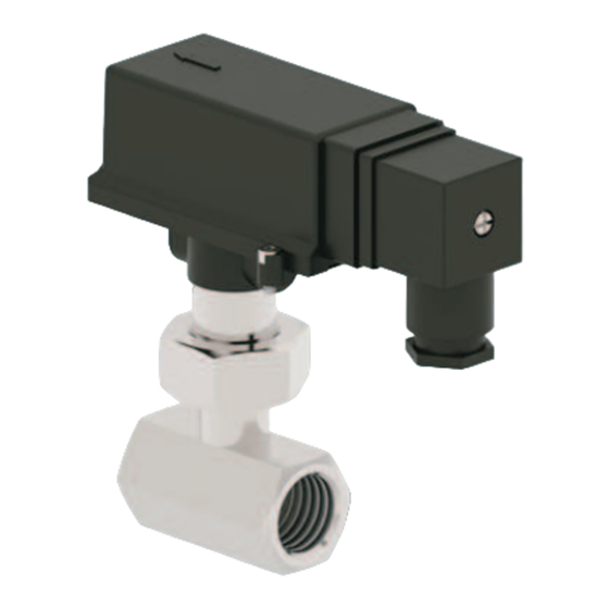
EFS
Model :
FLOW SWITCH
: Note
: Disposal
1
Model : 19-2021-007
Advertisement
Table of Contents

Related Manuals for ENSIM SENSORS EFS


Summary of Contents for ENSIM SENSORS EFS
-
Page 1: Table Of Contents
Information in this manual is reviewed and completely reliable. Responsibility is not assumed due to any typing error. Products in this manual are available only for information purpose and they may be changed without notice. Models : EFS 05s / 05sx / 05p / 05px EFS 06s / 06sx / 06p / 06px EFS 08s/10s/15s/20s/25s/32s/40s/50s... -
Page 2: General Information
1.2. Information about Areas of Use EFS is used in order to check safely whether there is flow or not by detecting movement of liquids inside the pipe. It provides information about flow with high reliability without spending energy in cooling water or lubricating oil circuits, in the devices such as flash heater, central heating boiler and heater. - Page 3 Body T Body FLOW Thread Palette FLOW Palette Technical Specifications : MODEL Stainless Type (EFS ..s) Plastic Type (EFS ..p) Body+Thread+Nut AISI 304 St.St. (Opt. AISI 316 St.St.) Polypropylene T Body AISI 304 St.St. (Opt. AISI 316 St.St.) Polypropylene Polypropylene...
- Page 4 1.5. Target Group This operating manual has been prepared for qualified technical personnel. 1.6. Security Notes Following notes should be taken into consideration in order to avoid dangers which can occur on the operator and around the ambient: Installation, operation and maintenance of this instrument should be made only by people who have read the operating manual and who are knowledgeable about work safety! It should be complied with work safety, accident prevention regulations and national installation standards.
-
Page 5: Installation
2. Installation 2.1. General Notes Installation of the instrument should be made only by authorized personnel. Do not apply force to the instrument during the installation! Do not use the level indicator with a greater pressure than recommended pressure. Do not forget that instrument is precise, carry it carefully and prevent to be damaged. It should be guaranteed that there are not any magnetic particles. - Page 6 2.5 . Reed Relay and Protection Circuit Inductive Load When reed switch is used for loads such as electromagnetic relay ,contactor or solenoid, reed switch may be exposed to very high voltage depending on value of inductive load. This causes either failure of switch or shortening its service life. Therefore, it is recommended to be used as follows depending on used voltage, for the purpose of protection of switch.
- Page 7 2.6. Dimensions and Working Ranges : EFS 05s , EFS 06s PALETTE FLOW Pipe Connection Max. Flow Rising Falling hex-HEX Palette Size Size (m³ / h) Flow Rate Flow Rate (mm) (mm) MODEL Water (m³ / h) (m³ / h)
- Page 8 EFS 08s , EFS 10s EFS 15s , EFS 20s EFS 25s , EFS 32s EFS 40s , EFS 50s PALETTE FLOW Ød Pipe Connection Max. Flow Rising Falling Palette (mm) (mm) d Ø Size Size (L / min) Flow Rate...
- Page 9 Cable EFS 05sx , EFS 06sx (1 m) PALETTE FLOW Pipe Connection Max. Flow Rising Falling hex-HEX Palette Size Size (m³ / h) Flow Rate Flow Rate (mm) (mm) MODEL Water (m³ / h) (m³ / h) (mm) Water Water...
- Page 10 Size (L / min) Flow Rate Flow Rate MODEL Water (L / min) (L / min) (mm) Water Water EFS 20cx EFS 20cx DN 20 Ø 9 EFS 25cx EFS 25cx DN 25 11,7 10,5 Ø 13 EFS 32cx EFS 32cx...
- Page 11 EFS 15px Cable (1 m) Body , PP Nut, PP PALETTE FLOW Ød T-Body Pipe Connection Max Flow Rising Falling Palette (mm) d Ø Size Size (m³ / h) Flow Rate Flow Rate (mm) MODEL D / D1 Water (L / min)
- Page 12 NC Reed Relay..........07 OPTIONAL None............../ 0 Special................x EXAMPLE EFS 05s - 0 - 002 - 002 - 50 - 0106 - 06 / 0 EFS 05s Flow Switch , 316 Stainless Steel , 1/2 ” BSP Male Thread , NO Contact...
- Page 13 WARNING !!! 2.8. Please pay attention to following matters in order to operate your flow switch properly. Please do not mount It should be placed Do not pull the cable strongly, Please keep away from magnetic materials slant way, otherwise in such a manner that otherwise the characteristics like iron board ;...
-
Page 14: Failure Detection
3. Failure Delection Breakdown Probable cause Failure detection\correction Pedal was broken or bent - The product was not used in compatible with fluid flow. -Check the flow range and use in compatible paller - The product was not used in compatible with fluid pressure. with the flow.
Need help?
Do you have a question about the EFS and is the answer not in the manual?
Questions and answers