Table of Contents
Advertisement
Quick Links
TABLE OF CONTENTS
1. INTRODUCTION...................................................................................................
2. IMPORTANT SAFETY PRECAUTIONS................................................................
3. LIST OF PARTS....................................................................................................
4.
STEP1 Support Cover Removal..........................................................................
Pedestal and Display Installation..............................
STEP3 Handlebar Installation..............................................................................
STEP4 Seat Back Installation..............................................................................
Seat Adjustment Handle Installation..........................
STEP6 Cover and Seat Bottom Installation.........................................................
STEP7 Pedal Installation.....................................................................................
Bike Placement.........................................................
Leveler Adjustment....................................................
STEP10
Power Cord Installation..............................................
STEP11
Seat Position Adjustment...........................................
DISPLAY Overview................................................................................................
DISPLAY Windows................................................................................................
DISPLAY Keys.......................................................................................................
DISPLAY Specifications.........................................................................................
6.
Safety Get On/Off............................................................................
7.
HEART RATE Telemetry........................................................................................
HEART RATE Contact...........................................................................................
9.
HOW HARD SHOULD I EXERCISE?....................................................................
HOW LONG SHOULD I EXERCISE?....................................................................
HOW OFTEN SHOULD I EXERCISE?..................................................................
10.
USER PARAMETER SETTING...........................................................................
11. MAINTENANCE ..................................................................................................
12.
Error Message.....................................................................................................
Fuse Replacement Instructions...........................................................................
13. BLOCK DIAGRAM...............................................................................................
14.
APPENDIXES......................................................................................................
APPENDIXES Exploded Diagram.......................................................................
SPORTSART C55R
......................................................................................
.................................................................................................
...........................................................................
.............................................................................................
Schedule...................................................................................
Task List...................................................................................
One-Year Maintenance Log.....................................................
RECUMBENT
.....................................................................
..................................................................
...................................................................
BIKE
..............................
..............................
...............................
..............................
..............................
..............................
1
2
6
9
11
14
18
20
22
26
27
28
29
30
33
33
34
34
35
36
37
38
38
40
42
43
43
45
45
45
46
47
47
48
49
50
51
51
52
53
53
Advertisement
Table of Contents

Related Manuals for SportsArt Fitness C55R


Summary of Contents for SportsArt Fitness C55R
-
Page 1: Table Of Contents
Bike Placement..................STEP9 Leveler Adjustment.................. STEP10 Power Cord Installation................STEP11 Seat Position Adjustment................. 5. UNDERSTANDING THE C55R DISPLAY CONSOLE DISPLAY Overview....................DISPLAY Windows....................DISPLAY Keys....................... DISPLAY Specifications..................OPERATING THE C55R EXERCISE BIKE OPERATION Safety Operating Area .............. -
Page 2: Introduction
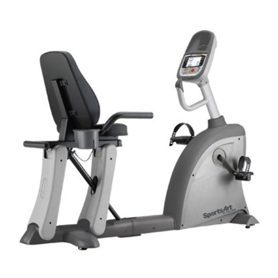
Congratulations on your purchase one of the finest pieces of exercise equipment on the market today, the SportsArt C55R Upright Bike. Constructed of high quality materials and designed for years of trouble-free usage, the C55R exercise bike will become an integral part of your fitness regimen. -
Page 3: Important Safety Precautions
2. IMPORTANT SAFETY PRECAUTIONS Never allow children 12 or younger on or near the equipment. Do not use accessories or parts that are not specifically recommended by the manufacturer (SportsArt). Such parts might cause injuries or cause the unit to fail and void the warranty. - Page 4 If you need to remove the cover for repair or maintenance, be sure to contact the service station or dealer to deal with, do not operate on their own. This bike is not intended for use by persons (including children 12 or younger) with reduced physical, sensory or mental capabilities, or lack of experience and knowledge, unless they have been given supervision or instruction concerning use of this bike by a person responsible for their safety.
-
Page 7: List Of Parts
3. LIST OF PARTS Assembly Parts Name Qty No. Description Body Left/right horizontal cover Display Left/right seat support cover (front) Left/right covers for display Left/right seat support cover (rear) Pedestal Seat bottom Pedestal collar Pedal set Handlebars Cup holder Seat back support Power cord Seat back Hardware kit... - Page 8 Hardware Kit Name Name Specification Specification Notes Notes Screw socket Mushroom top Phillips screw M4*L16 Mushroom top Phillips screw M5*L12 Serrated washer BW5 3/16 Mushroom top inner hex screw M8*L20 Flat washer M8*D17*t1.5 Spring washer M8*t2.0 Open-end wrench M13*15mm L-shaped Allen wrench L-shaped Allen wrench Fuse Hardware kit...
- Page 9 Note: For brevity, throughout this manual, the word screws is used where screws, " " washers, and other hardware may be involved. Note that some parts are marked L " " for left and " R for right. Product side determinations correspond to the left/right sides "...
-
Page 10: Assembling Your Exercise Bike Step2
4. ASSEMBLING YOUR EXERCISE BIKE STEP 1 Support Cover Removal 1-1. Loosen left/right seat support cover screws (31). Then remove left/right seat support covers (A11)(A12). - Page 11 1-2. Insert screw sockets (21) into the bike frame as shown. Total: 16, eight on each side.
- Page 12 STEP 2 Pedestal and Display Installation...
- Page 13 Follow steps a - i to install the pedestal and display. (a) First, remove screws (32) from the back of the display (A2). (b) Connect the data cable to the display (A2) as shown. Then tuck excess cable into the pedestal to protect it. (c) Use screws (32) to secure the display (A2) to the pedestal (A4).
- Page 14 (f) First, remove screws (34) from the pedestal base. (g) Insert the pedestal collar (A5) onto the pedestal (A4) as shown. (h) Connect the data cable in the pedestal to that in the pedestal base as shown. (i) Insert the pedestal into the pedestal base in the body (A1) as shown. Then secure screws (34) in order #1, #2, #3.
-
Page 15: Step3 Handlebar Installation
STEP 3 Handlebar Installation... - Page 16 Follow steps (a c) to install handlebars. (a) Hold the handlebars (A6) onto the frame (A1). Use screws (24) to secure the handlebars onto the frame. (b) Remove the water bottle holder screws(35) from the handlebars. (c) Hold the water bottle holder (A15) onto the handlebars and secure its screws (35).
- Page 17 Option: Contact Heart Rate Handlebars...
- Page 18 Please assemble handlebars as shown in steps (a c) below. (a) Place the handlebars (A6) on the unit as shown. Secure the handlebars in place with screws (24). (Please note that for brevity the words "screws" is used when washers and other hardware may be involved.) (b) Pull cable (43) from the frame (A1).
-
Page 19: Step4 Seat Back Installation
STEP 4 Seat Back Installation... - Page 20 Follow steps (a d) to install the seat back. (a) First, remove screws (36) from the seat back support (A7). (b) Insert the seat back support into its base on the frame (A1). Secure it with screws (36). (c) Remove screws (36) from the seat back (A8). (d) Hold the seat back (A8) onto the seat back support (A7) and secure it with screws (36).
- Page 21 STEP 5 Seat Adjustment Handle Installation 5-1. Follow steps (a c) to install the seat adjustment handle. (a) First, remove the handle (39) from the gas spring. (b) Next, remove the screws (38) from the handle. (c) Then, use screws (38) to secure the seat adjustment handle (39) onto the handlebars (A6).
- Page 22 5-2. As shown in the exploded view diagram, hold up the handle (39) to adjust the seat position. 5-3. For convenience, the gas spring automatically moves the seat upward when there is no weight on the seat. Release the handle when the seat is up all the way.
-
Page 23: Step6 Cover And Seat Bottom Installation
STEP 6 Cover and Seat Bottom Installation... - Page 24 Adjust the seat upward to make room for cover installation. Set the back leg cover (A9) in place on the frame. Loosely secure screws (22) (23). After all screws are in place, tighten them. Then put left/right horizontal covers (A10) in place. Thread all the screws (22) into place loosely.
- Page 25 Note that seat support covers have front (11) and back (12) and left (L) and right (R) designations. In the diagram below, A11L and A11R represent left and right front covers respectively; A12L and A12R represent left and right back covers respectively. Also, note that the front covers have a cut-out (Compare A and B below) for the gas spring.
- Page 26 First, remove screws (37) from the seat bottom (A13). Set the seat bottom onto the handlebar assembly. Then secure screws (37) into the seat bottom.
-
Page 27: Step7 Pedal Installation
STEP 7 Pedal Installation Each pedal is marked left or right. Left/right designations correspond to the exercisers' left/right sides in the position at which they workout on the product. Install pedals (A14) on the appropriate sides of the bike. Note: the left pedal screws in counterclockwise; the right pedal screws in clockwise. -
Page 28: Step9
STEP 8 Bike Placement Follow steps (a,b,c) to roll the bike into place. (a) Stand behind the bike. Grasp the moving handle with both hands and lift. (b) With the bike at a slant, push the bike. (c) Front rollers allow the bike to be rolled into place. -
Page 29: Leveler Adjustment
STEP 9 Leveler Adjustment Put the bike where it will be ridden. Sit on the bike. Inspect it by shifting your weight from side to side. Does the bike rock from side to side? If so, level it. (a) Loosen the leveler nut. (b) Rotate rubber feet downward until they touch the floor. -
Page 30: Power Cord Installation
STEP 10 Power Cord Installation Insert the power cord into the socket on the product. Insert the other end of the cord into the power socket in the wall. To turn on the machine, press the side of the power switch with a line mark. - Page 31 STEP 11 Seat Position Adjustment The seat position on C55R can be adjusted to suit people of different heights. The position can be altered in two ways: an automatic gas spring moves the seat within a set range; and the placement of the gas spring's connection to the frame changes the range of movement.
- Page 32 To adjust the seat position via holes in the frame, follow the instructions below. The frame has two sets of holes, one in front (a) and one more toward the back (b), for the gas spring connection. Connecting the gas spring at the front hole makes the seat closer and lower in relation to the display.
- Page 33 3. Disconnect and reconnect the gas spring as follows. a. Remove the screw(42) and bushing (41). b. Tap out the axle pin (40). c. Align the end of the gas spring with the desired hole in the frame. Insert the axle pin(40) into the hole in the frame and that in the gas spring.
-
Page 34: Understanding The C55R Display Console
5. UNDERSTANDING THE C55R DISPLAY CONSOLE DISPLAY Overview Workout Profile Screen Workout profile appears from right to left, top to bottom. Feedback includes workout level, time, RPM, and calories. DISPLAY Windows ˙ WORKOUT PROFILE SCREEN - Shows user settings or prompts, including USER,AGE,WT, KG, LB indicators. -
Page 35: Display Keys
DISPLAY Keys WORKOUT LEVEL ▲/▼ 1. In a workout program, press WORKOUT LEVEL ▲/▼ to adjust the resistance level. 2. In the user set up mode, press WORKOUT LEVEL ▲/▼ to adjust USER/Age/Weight/Time. STOP/HOLD TO RESET - STOP In an exercise program, press the STOP key to exit the program. -... -
Page 36: Operating The C55R Exercise Bike Operation Safety Operating Area
6. OPERATING THE C55R EXERCISE BIKE OPERATION Safety Operating Area (a) Safety clearance required as shown below. Do not allow people to be near this area when operating. (b) Noise emission under load is higher than without load. -
Page 37: Operation Safety Get On/Off
OPERATION Safety Get On/Off (a) Sit on the cycle and then hold the handles to steady self while stepping into the pedals as shown below. (b) Wait until pedals come to a complete stop and then carefully stepping off the cycle. -
Page 38: Operation Proper Workout Position
OPERATION Proper Workout Position (a) User proper workout position as shown below. (b) Over exercising or improper workout form may result in serious injury. -
Page 39: Operation Quick Start
OPERATION Quick Start There are two ways to start operating the C55R bike. Either press the QUICK START key or press the START key. QUICK START mode allows you to start exercising immediately, without the benefit of a user ID. START mode allows you to use a user ID. - Page 40 CLEARING OUT USER SETTINGS While a user ID number appears on the screen, press and hold STOP + ENTER keys simultaneously for three seconds to clear out user time, distance, and calories. The unit clears accumulated values while beeping three times. Then the USER selection screen appears.
-
Page 41: Operation Workout Programs
OPERATION Workout Programs When the exercise program indicator flashes, press INTERVAL, RANDOM, TRACK, or HILL keys to immediately start working out. TRACK 1. One lap is 400 meters (0.25 mile). 2. Resistance is preset to level one. Press WORKOUT LEVEL ▲/▼ to adjust workout level. - Page 42 PRESSING PAUSE FROM A PROGRAM 1. In any exercise program, if you stop pedaling, "PAUSE" scrolls across the screen. Continue to pedal or press START to return to your exercise program. 2. If you don't pedal for two minutes after PAUSE is pressed, the start up screen appears.
-
Page 43: Internal Setting
7. INTERNAL SETTINGS SHOW UNIT TOTAL DISTANCE In the USER selection setting, simultaneously press and hold WORKOUT LEVEL ▼ + WORKOUT LEVEL ▲ for three seconds. Time and distance windows show total distance as eight digits. Units appear as MILE or KM. Press the ENTER key to see total time. -
Page 44: About Heart Rate Detection And Presentation
8. ABOUT HEART RATE DETECTION AND PRESENTATION Heart rate detection functions are optional and may not be included in your particular model. If your bike is equipped with these functions, please note the following information. HEART RATE Telemetry The word "telemetry heart rate" refers to the detection of the heart rate, usually via a strap worn on the exerciser's chest and transmitted over the air for reception by a receiver built into the product. - Page 45 4.The vibration of treadmills at speeds over 4 mph / 6.4 kph makes heart rate detection difficult. Also, if your hands move, heart rate detection becomes difficult. SUGGESTIONS For better heart rate detection, keep hands in one place on the contact plates. Or wear a telemetry heart rate strap on your chest.
-
Page 46: Guidelines For Exercise How Hard Should I Exercise
9. GUIDELINES FOR EXERCISE HOW HARD SHOULD I EXERCISE? Studies show that to achieve the benefits of aerobic exercise, it is necessary to work within your training zone. Your training zone depends on your age and level of fitness. The above chart indicates the recommended Heart Rate training zones (darkened area of the chart). -
Page 47: User Parameter Setting
10. USER PARAMETER SETTING To check system default settings, at the start up screen (when the message appears: "Select PROGRAM or QUICK START"), hold the ENTER key for three seconds. The following appears: 1. MPH or KPH (speed units). Press up or down keys to toggle between the two unit selections. -
Page 48: Maintenance
11. MAINTENANCE This section covers maintenance topics and includes a maintenance sched-ule, task list, and log. MAINTENACE Safety Precautions ˙ Please follow standard safety precautions when servicing on this product. ˙Do NOT use a damp towel to clean the product and do perform the following maintenances. -
Page 49: Maintenance Schedule
MAINTENANCE Schedule Area Exterior Clean. Screws Inspect for looseness. Wipe Clean with a damp Seat back and bottom cloth. Inspect for looseness. Pedals Tighten if needed. Inspect for normal operation. Gas spring... -
Page 50: Maintenance Task List
MAINTENACE Task List Like cars, fitness products require maintenance. Regular maintenance extends product life, and failure to maintain products can void the manufacturer’s warranty. Copy the maintenance log sheet, and record maintenance work for each fitness product. Daily tasks 1. Use a clean, lint-free towel, dampened with a mixture of Simple Green® all- purpose cleaner and water, to thoroughly clean the product exterior. -
Page 51: Maintenance One-Year Maintenance Log
MAINTENANCE One-Year Maintenance Log Facility : Supervisor: Product Model Number : Serial Number: Start Date: End Date: Daily Tasks Weeks 1-7 Weeks 8-14 Weeks 15-21 Weeks 22-28 Completed Daily Tasks Weeks 29-35 Weeks 36-42 Weeks 43-49 Weeks 50-52 Completed Weekly Tasks Weeks 1-7 Weeks 8-14 Weeks 15-21... -
Page 52: Troubleshooting Error Message
12. TROUBLE SHOOTING ERROR Message ERR 7: This means the VR voltage exceeds the specified range of 0.4 VDC to 4.7 VDC. Please consult a qualified repair technician. FUSE Replacement Instructions If the display does not light when you turn on unit power, please inspect the fuse. Fuses protect drive board components in the event of high amp draw. -
Page 53: Block Diagram
13. BLOCK DIAGRAM E80 CTL Board Receiver board Power Transformer C51DRV Magnetic Board Speed Sensor... -
Page 54: Appendixes
14. APPENDIXES APPENDIXES Exploded Diagram Note: We reserve the right to revise the following diagrams at any time without notice or obligation to notify any person of such revisions or changes. Please visit our official website www.gosportsart.com for the latest version. - Page 55 APPENDIXES Exploded Diagram (Continued)
- Page 56 APPENDIXES Exploded Diagram (Continued)
- Page 57 Your Authorized Distributor...
Need help?
Do you have a question about the C55R and is the answer not in the manual?
Questions and answers