
Related Manuals for SportsArt Fitness C535R


Summary of Contents for SportsArt Fitness C535R
- Page 1 C535R LED BIKE Owner’s Manual 2014.12 (W) Sports Art Industrial Co., Ltd. ISO 9001/14001 Certified No. 11, Gong Huan Rd. Tainan City, Taiwan R.O.C. www.gosportsart.com...
-
Page 2: Table Of Contents
STEP 7 Bike Placement ..............STEP 8 Level the Bike ................ STEP 9 Seat Position Adjustment ............STEP 10 How to Connect the Ground Wire ......... 5. UNDERSTAND THE C535R DISPLAY ........... DISPLAY Overview ................DISPLAY Specifications ............... DISPLAY Windows ................33 DISPLAY Keys .................. -
Page 3: Introduction
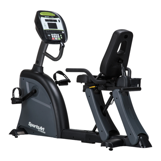
1. INTRODUCTION Congratulations on your purchase of one of the finest exercise products on the market today, the C535R recumbent exercise cycle Constructed of high quality materials and designed for years of reliable usage, this product was made to become an integral part of your commercial fitness venue. -
Page 4: Safety Precautions
2. SAfETy PRECAUTIONS Your SportsArt bike was designed and built for optimum safety. However certain precautions apply whenever you use your bike. Please read the entire manual before assembly and operation. Also, please note the following safety precautions: ● Please read the instructions carefully and install the bike as instructed. ●... - Page 5 2. SAfETy PRECAUTIONS (CONTINUED) Caution If you feel any pain or abnormal sensation, STOP YOUR WORKOUT and consult your physician immediately. Work within your recommended exer- cise level. DO NOT work to exhaustion. Before beginning any exercise program, you should consult with your doc- tor.
- Page 6 2. CONSIgNES DE SéCURITé • Votre vélo SportsArt a été conçu et fabriqué afin d’assurer une sécurité optimale. Cependant certaines précautions s’appliquent chaque fois que vous utilisez votre vélo de course. • Lisez entièrement le manuel avant l’assemblage et l’utilisation. Veuillez aussi noter les consignes de sécurité...
- Page 7 2. CONSIgNES DE SéCURITé (SUITE) Ce vélo n’est pas destiné à être utilisé par des personnes (y compris des enfants) dont les capacités physiques, sensorielles ou mentales sont réduites ou qui ne disposent pas de l’expérience ou du savoir nécessaires, sauf si celles-ci ont au préalable été...
-
Page 8: List Of Parts
3. LIST Of PARTS Assembly Parts No. Name Qty. No. Name Qty. A1 Pedestal and display 1 Back foot cover A2 Pedestal collar A10 Left/right horizontal cover Left/right seat support cover Main frame and (front have cut-away for body Seat carriage) Left/right seat support cover A4 Spring cover (rear have no cut-away) - Page 9 3. LIST Of PARTS (CONTINUED) Components in the Hardware Kit Name Qty. Specification Notes Mushroomtop Phillips screw M4*L16 Screw socket Mushroomtop Phillips screw M5*L12 Serrated washer BW5 3/16 Yellow/Green Ground wire L1500 L-shaped Allen wrench L-shaped Allen wrench Double open-end wrench 13*15 Screwdriver handle Green...
-
Page 10: Assemble The Product
4. ASSEMBLE THE PRODUCT Follow instructions below to assemble this product. Note that in this manual the words “left” and “right” are used to refer to the product and its parts. As such, these designations correspond to the “left” and “right” sides of a person in position to exercise on this product. -
Page 11: Step 2 Seat Back And Adjustment Handle Installation
STEP 2 Seat Back and Adjustment Handle Installation... - Page 12 STEP 2 Seat Back & Adjustment Handle Installation (Cont.) Follow steps (a) through (h) to install the gas spring and seat back. (a) First, remove the gas spring set pin (51) from the product frame. (b) Align the lower part of the gas spring (A8) with the pin hole in the frame. (c) Insert the pin (51) through both the frame and the gas spring and secure it with the R-clip...
- Page 13 STEP 2 Seat Back & Adjustment Handle Installation (Cont.) (d) Insert the gas spring cover (A4) onto the gas spring. (e) Secure the cover screws (21). (f) Remove the gas spring set pin (51) and R-clip from the seat back frame. (g) Align the seat back frame and the gas spring upper connector.
- Page 14 STEP 2 Seat Back & Adjustment Handle Installation (Cont.) Follow steps (a) through (f) to install the seat adjustment handles. (a) Detach one seat adjustment handle (A7) from the top of the gas spring. (b) Remove screws (52) from the handle. (c) Hold the handle (A7) onto the left handle base.
-
Page 15: Step 3 Pedestal And Display Installation
STEP 3 Pedestal and Display Installation... - Page 16 STEP 3 Pedestal and Display Installation (Continued) Follow steps (a) through (d) to install the pedestal and display. (a) Remove screws (53) attached to the pedestal base. (b) Insert the pedestal collar (A2) onto the pedestal (A1). (c) Connect the data cables. (d) Insert the pedestal into its mount on the frame and then secure screws (53) in the following order: #1, #2, #3.
-
Page 17: Step 4 Handlebar Installation
STEP 4 Handlebar Installation... - Page 18 STEP 4 Handlebar Installation (Continued) 4-1. Pull the seat back adjustment handle (A7) up to allow the seat back to move forward, allowing installation of the handlebars. 4-2. Remove screws (54) from the handlebar base on the product frame as shown.
- Page 19 STEP 4 Handlebar Installation (Continued) 4-3. Insert the handlebars (A6) between the seat back and the gas spring. 4-4. Secure the wire connections, tuck cables into a safe position, and secure handlebars with screws (54).
- Page 20 STEP 4 Handlebar Installation (Continued) 4-5. Remove screws (55) from the handlebars and then set the cup holder (A5) in place and secure its screws (55). 4-6. Remove the seat support cover screws (56), and remove the covers (A11R, A11L, A12R, A12L).
-
Page 21: Step 5 Cover And Seat Bottom Installation
STEP 5 Cover and Seat Bottom Installation... - Page 22 STEP 5 Cover and Seat Bottom Installation (Continued) 5-1. Lift up the seat back adjustment handle (A7), allowing the seat back to move forward, into position for seat support cover installation. 5-2. Insert screw sockets (22) into place on the frame as shown. There are eight screw sockets on each side.
- Page 23 STEP 5 Cover and Seat Bottom Installation (Continued) 5-3. Set the back foot cover (A9) into place on the frame. Secure it with screws (21) and (23). Note: Use screws (23) in the position shown. 5-4. Hold left/right horizontal covers (A10R, A10L) onto the product and secure them with screws (21).
- Page 24 STEP 5 Cover and Seat Bottom Installation (Continued) 5-5. Identify seat support covers (A11R, A11L, A12R, A12L). Front covers have the cut-away for the gas spring. Hold covers in place and secure them with screws (56). 5-6. Remove screws (57) from the product frame and set the cover (A16) into place on the product frame and secure them with screws (57).
- Page 25 STEP 5 Cover and Seat Bottom Installation (Continued) 5-7. Remove screws (54) from the seat bottom (A13). 5-8. Place the seat bottom (A13) on the bike frame and secure it with screws (54).
-
Page 26: Step 6 Pedal Installation
STEP 6 Pedal Installation Each pedal is marked left or right. Left/right designations correspond to the exercisers’ left/right sides in the position at which they workout on the product. Install pedals (A14) on the appropriate sides of the bike. Note: The left pedal screws in counterclockwise;... -
Page 27: Step 7 Bike Placement
STEP 7 Bike Placement Follow steps (a) through (c) to roll the bike into place. (a) Stand behind the bike. Grasp the moving handle with both hands and lift. (b) With the bike at a slant, push the bike. (c) Front rollers allow the bike to be rolled into place. -
Page 28: Step 8 Level The Bike
STEP 8 Level the Bike For the user’s safety and the proper functioning of the product, this bike must sit level on a flat floor. If necessary, adjust the levelers by following instructions (a) through (c) below. (a) Loosen the leveler nut. (b) Rotate the leveler foot downward so it firmly touches the floor. -
Page 29: Step 9 Seat Position Adjustment
STEP 9 Seat Position Adjustment The seat position on C535R can be adjusted to suit people of different heights. The position can be altered in two ways: an automatic gas spring moves the seat within a set range; and the placement of the gas spring’s connection to the frame changes the range of movement. - Page 30 STEP 9 Seat Position Adjustment (Continued) To adjust the seat position via holes in the frame, follow the instructions below. The frame has two sets of holes, one in front (a) and one more toward the back (b), for the gas spring connection. Connecting the gas spring at the front hole makes the seat closer and lower in relation to the display.
- Page 31 STEP 9 Seat Position Adjustment (Continued) 3. Disconnect and reconnect the gas spring as steps (a) through (c) below. (a) Remove the screw and bushing. (b) Tap out the axle pin with a tool. (c) Align the end of the gas spring with the desired hole in the frame. Finally, insert the axle pin into the hole in the frame and that in the gas spring and then secure the bushing and screw.
-
Page 32: Step 10 How To Connect The Ground Wire
STEP 10 How to Connect the ground Wire Note: The installation of a ground wire is required by European safety standards. The ground wire is not required by North American safety standards. ground wire installation: Use a screw to secure one end of the ground wire to the product frame as shown. -
Page 33: Understand The C535R Display
5. UNDERSTAND THE C535R DISPLAy DISPLAy Overview The C535R recumbent cycle is designed for user convenience. With better feedback about your workout, you get better results. The following explains the display key and window functions. Please read this manual, understand the display functions, and thereby get optimum enjoyment and benefit from this product. -
Page 34: Display Specifications
DISPLAy Specifications ● Workout level (resistance level): 1 - 40 ● METS: 0.0 - 99.0 ● Time: 0:00 - 300:00 ● Distance: 0.00 - 9999 km or mile ● Calories: 0.0 - 9999 kcal ● RPM: 5 – 150 (Range shown) ●... - Page 35 DISPLAy Keys (Continued) fAT BURN – This workout program provides 1 - 20 different difficulties to select from. fIT TEST – Press this key to enter a FIT TEST program and start the fitness test. CUSTOM HR – This heart rate control program allows you to set your own target heart rate.
-
Page 36: Operate The Product
6. OPERATE THE PRODUCT There are two ways to start operating this product, either through the QUICK START mode or through a workout program/goal. OPERATION Quick Start Time, distance and calories will count up. If a workout time limit is activated, time will count down, but distance and calories will count up continuously. -
Page 37: Operation Display
OPERATION Start a Workout Program (Continued) ● The CALORIE setting range is from 100 to 9999 kCal, with a default value of 100 kCal. Use ▲/▼ keys or numeric keys (0-9) to make your selection. Press the ENTER key to confirm your setting and proceed to the age setting. -
Page 38: Operation Cool Down
OPERATION Cool Down Once the workout goal (time, distance, or calorie expenditure) has been obtained, the product will enter a two-minute cool down period. The display will count down from two to zero. When the countdown reaches zero, the cool down period will end. The message “REVIEW SUMMARY”... - Page 39 OPERATION Workout Programs (Continued) RANDOM This program provides a near infinite number of randomly generated workouts. A new workout illustration appears each time the RANDOM key is pressed. fAT BURN In this program, there are 1-20 different difficulty levels to select from. During program setting, before entering program mode, you must first select the STAGE, range from 1 - 20 (default value is STAGE 5).
- Page 40 OPERATION Workout Programs (Continued) CARDIO/WEIgHT LOSS/CUSTOM HR In these heart rate control programs, the resistance level will automatically change to keep the exerciser’s pulse at the optimum rate for achieving his or her fitness goals. Target heart rates are calculated based on a standard “maximum” heart rate for the exerciser’s age.
-
Page 41: Operation User Preferences And Component Versions
OPERATION User Preferences and Component Versions Basic settings determine units of measure and show total distance and time, along with display and drive board program version numbers. To access this information, at the startup banner screen, hold the CHANGE DISPLAY key for two seconds. -
Page 42: About Heart Rate Detection
7. ABOUT HEART RATE DETECTION Heart rate detection functions are selected at the time of purchase. Not every product has every type of heart rate detection. The following explains factors that influence the performance of two of the most common types of heart rate detection devices. -
Page 43: Guidelines For Exercise
Note that in dry areas in particular, static electricity can interfere with unit operation and shock people. To discharge static electricity from your body, touch something else before touching metal on the product. 8. gUIDELINES fOR EXERCISE HOW HARD SHOULD I EXERCISE? Studies show that to benefit from aerobic exercise, people need to maintain a certain heart rate during their workouts. -
Page 44: Accessories
9. ACCESSORIES There are accessories attached to this console; some are standard and some are optional. The following explains the details of each accessory and its function. USB CHARgER (Standard) The USB charger will provide 5V 500mA voltage for the smart phone or other devices charging. -
Page 45: Accessories Entertainment Cap
9. ACCESSORIES (CONTINUED) Entertainment Cap (a) RFID member card slot: work with both optional SA WELL+ and ECOFIT member cards. (Not available yet.) (b) Bluetooth/WIFI connection button: press this button to pair the smart phone SA WELL+ App. (c) USB port: this port is used for device charging as well as optional data transferring. -
Page 46: Accessories Mye Wireless Tv Audio_Channel Receivers
9. ACCESSORIES (CONTINUED) MyE Wireless TV Audio_Channel Receivers: If your equipment has been installed MYE Wireless TV Audio_Channel Receivers, the display must has Channel Keys. Please make sure your equipment is with the correct sticker as below. (a) None Treadmill (Bike, Elliptical and Stepper...etc.) Left display: Without Channel Keys. - Page 47 9. ACCESSORIES (CONTINUED) MyE Wireless TV Audio_Channel Receivers fuctions: 1. The receiver has two kinds of module as below. (Note: MyE Wireless TV Audio_Channel Receivers and Module not provided.) (1). MC3R-9(900MHZ) must work with MYE Wireless TV Audio_Channel Receivers MWTD-S9. (2).
-
Page 48: Maintenance
10. MAINTENANCE Maintenance topics are presented below in the following order: error messages, lubrication the seat carriage, maintenance schedule, task list, one-year maintenance log, and electronics block diagram. MAINTENANCE Messages The following message can appear on this product for diagnostic purposes. ERR0R_8_x Error messages will appear on the display when the Micro Inverter or stride- length drive board communication is abnormal. -
Page 49: Maintenance Schedule
MAINTENANCE Schedule Area Day Week Month Quarter year Notes 1 Exterior Clean Inspect for 2 Screws looseness. Secure if necessary. Seat Wipe clean with a back and damp cloth. bottom Inspect for 4 Pedals looseness. Tighten if needed. Inspect for normal spring operation. -
Page 50: Maintenance Task List (Cycles)
MAINTENANCE Task List (Cycles) Like cars, fitness products require maintenance. Regular maintenance extends product life, and failure to maintain products can void the manufacturer’s warranty. Copy the maintenance log sheet, and record maintenance work for each fitness product. Daily tasks 1. -
Page 51: Maintenance One-Year Maintenance Log
MAINTENANCE One-year Maintenance Log Facility:_______________________ Supervisor:____________________ Product model number:__________ Serial number:_________________ Start date: ____________________ End date:_____________________ Daily Tasks Weeks 1-7 Weeks 8-14 Weeks 15-21 Week 22-28 Completed Daily Tasks Week 29-35 Week 36-42 Week 43-49 Week 50-52 Completed Weekly Tasks Weeks 1-7 Weeks 8-14 Weeks 15-21 Weeks 22-28... -
Page 52: Maintenance Electronics Block Diagram
MAINTENANCE Electronics Block Diagram RFID Board USB Board Control Board Continua Adapter Board Option CSAFE Board SA WELL+ Connection key HRC Board iPod Audio Board Head Phone Board Option Model no. board Optic sensor Drive Board Fuse DC Adaptor Jack Steel Wheels and Electromagnet Battery :Connector...
Need help?
Do you have a question about the C535R and is the answer not in the manual?
Questions and answers