
Related Manuals for Intersil ISL71010BM25EV1Z


Summary of Contents for Intersil ISL71010BM25EV1Z
- Page 1 ISL71010BM25EV1Z User’s Manual: Evaluation Board High Reliability Rev.0.00 Nov 2017...
-
Page 2: Specifications
Rev.0.00 Nov 2, 2017 Overview The ISL71010BM25EV1Z evaluation board measures the performance of the high precision 2.5V ISL71010B25 voltage reference. The reference has a wide input voltage range from 4V to 30V and an initial accuracy of ±0.05%. The voltage noise of 1.9µV in the 0.1Hz to 10Hz range and maximum output voltage temperature coefficient of 10ppm/°C... - Page 3 ISL71010BM25EV1Z 1. Overview VREF 10µF 0.1µF COMP VOUT 0.1µF TRIM VREF DACOUTx Serial Clock SCLK OUTxS Chip Select OUTxF Serial Data I/O SDIO Figure 1. ISL71010BM25EV1Z Block Diagram UG135 Rev.0.00 Page 3 of 13 Nov 2, 2017...
-
Page 4: Functional Description
2. Functional Description Functional Description The ISL71010BM25EV1Z evaluation board provides a simple platform to demonstrate the features and evaluate the performance of the ISL71010B25 voltage reference. It provides easy access to the ISL710101B25 IC pins. The schematic, bill of materials, and top silkscreen for the board are available on pages 6 through 8. - Page 5 ISL71010BM25EV1Z 2. Functional Description Quick Start Guide (1) Gather the external supply and equipment needed to operate the board: (a) 4V to 30V DC power supply (b) Precision Voltmeter (Agilent 3458A digital multimeter or equivalent) (2) Attach the evaluation board to a DC power supply at test points TP1 and TP2 labeled VIN and GND as shown Figure 2.
-
Page 6: Pcb Layout Guidelines
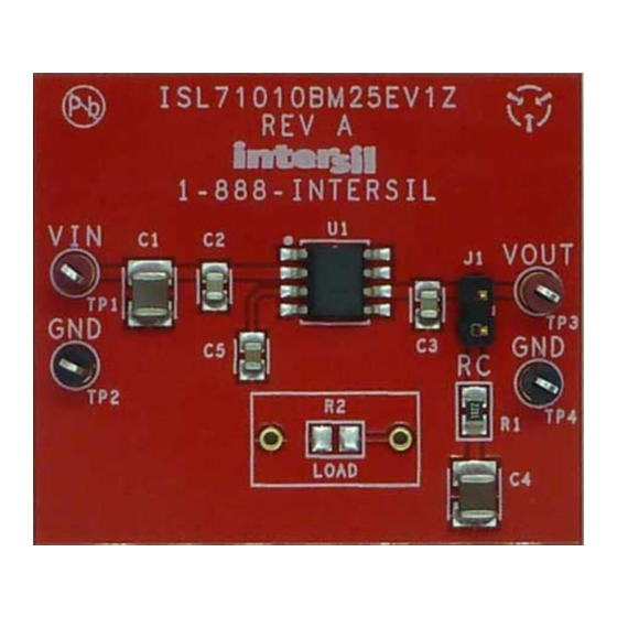
ISL71010BM25EV1Z 3. PCB Layout Guidelines PCB Layout Guidelines ISL71010BM25EV1Z Evaluation Board Figure 3. ISL71010BM25EV1Z Evaluation Board ISL71010BM25EV1Z Evaluation Board Schematic VOUT SOIC8 LOAD Figure 4. ISL71010BM25EV1Z Evaluation Board Schematic UG135 Rev.0.00 Page 6 of 13 Nov 2, 2017... -
Page 7: Bill Of Materials
ISL71010BM25EV1Z 3. PCB Layout Guidelines Bill of Materials Reference Manufacturer Designator Description Part Number PWB-PCB, ISL71010BM25EV1Z, Rev A, ROHS IMAGINEERING ISL71010BM25EV1ZREVAPCB CAP, SMD, 0805, 1000pF, 50V, 10%, X7R, ROHS PANASONIC ECJ-2VB1H102K C2,C3 CAP, SMD, 0805, 0.1µF, 50V, 10%, X7R, ROHS... - Page 8 ISL71010BM25EV1Z 3. PCB Layout Guidelines Figure 7. Top Layer Silk Screen UG135 Rev.0.00 Page 8 of 13 Nov 2, 2017...
-
Page 9: Typical Performance Curves
ISL71010BM25EV1Z 4. Typical Performance Curves Typical Performance Curves Recommended operation conditions, unless noted: V = 5V, I = 0mA, C = 0.1µF, COMP = 1nF, T = +25°C 2.503 2.503 2.5V +0.1% 2.502 2.502 2.5V+0.1% Unit3 Unit4 (V) 0mA +25°C 2.501... - Page 10 ISL71010BM25EV1Z 4. Typical Performance Curves Recommended operation conditions, unless noted: V = 5V, I = 0mA, C = 0.1µF, COMP = 1nF, T = +25°C (Continued) 1300 1000 1200 Unit 3 1100 +125°C +25°C 1000 Unit 1 Unit 2 -40°C Figure 13.
-
Page 11: Revision History
ISL71010BM25EV1Z 5. Revision History Revision History Rev. Date Description 0.00 Nov 2, 2017 Initial release UG135 Rev.0.00 Page 11 of 13 Nov 2, 2017... -
Page 12: Corporate Headquarters
IMPORTANT NOTICE AND DISCLAIMER RENESAS ELECTRONICS CORPORATION AND ITS SUBSIDIARIES (“RENESAS”) PROVIDES TECHNICAL SPECIFICATIONS AND RELIABILITY DATA (INCLUDING DATASHEETS), DESIGN RESOURCES (INCLUDING REFERENCE DESIGNS), APPLICATION OR OTHER DESIGN ADVICE, WEB TOOLS, SAFETY INFORMATION, AND OTHER RESOURCES “AS IS” AND WITH ALL FAULTS, AND DISCLAIMS ALL WARRANTIES, EXPRESS OR IMPLIED, INCLUDING, WITHOUT LIMITATION, ANY IMPLIED WARRANTIES OF MERCHANTABILITY, FITNESS FOR A PARTICULAR PURPOSE, OR NON-INFRINGEMENT OF THIRD PARTY INTELLECTUAL PROPERTY RIGHTS. - Page 13 ISL71010BM25EV1Z UG135...
Need help?
Do you have a question about the ISL71010BM25EV1Z and is the answer not in the manual?
Questions and answers