Table of Contents
Advertisement
Quick Links
ISL73041SEHEV1Z
The ISL73041SEHEV1Z evaluation board evaluates
the performance of the radiation-hardened
ISL73041SEH
12V half-bridge GaN FET driver in an
open-loop Buck configuration. The
ISL73041SEHEV1Z evaluation board includes the
GaN FET half-bridge driver, Renesas GaN FETs, and
a Buck converter power stage inductor and output
capacitors.
For more information about the ISL73041SEH, refer
to the ISL73041SEH Datasheet.
4.75V to 13.2V
Dead Time
Control
Figure 1. Application Diagram ISL73041SEH Driving GaN FET Half Bridge
R34UZ0012EU0101 Rev.1.01
Jun 21, 2023
VDD
PWM
ISL73041SEH
Half
RDU
Bridge
Driver
RDL
PVCC LDO
4.5V to 5.5V
Evaluation Board Manual
Features
▪ 4.75V to 13.2V VDD power supply range
▪ 300kHz to 1MHz PWM frequency range (external
component limited)
▪ Bridge voltage (V_BUS) range: Up to 13.2V
▪ 5V max recommended buck output voltage
(external component limited)
▪ Buck output load current up to 25A
Specifications
▪ Number of layers: 4
▪ PCB copper weight: 2oz
▪ Board revision: C
VBUS
BOOT
UG
PHS
LG
VOUT
Page 1
© 2023 Renesas Electronics
Advertisement
Table of Contents

Related Manuals for Intersil ISL73041SEHEV1Z


Summary of Contents for Intersil ISL73041SEHEV1Z
- Page 1 Evaluation Board Manual ISL73041SEHEV1Z Features The ISL73041SEHEV1Z evaluation board evaluates the performance of the radiation-hardened ▪ 4.75V to 13.2V VDD power supply range ISL73041SEH 12V half-bridge GaN FET driver in an ▪ 300kHz to 1MHz PWM frequency range (external open-loop Buck configuration. The...
-
Page 2: Table Of Contents
ISL73041SEHEV1Z Evaluation Board Manual Contents Functional Description ..............3 Quick Start Instructions . -
Page 3: Functional Description
V_OUT below 5V. Changing Power Inductor The ISL73041SEHEV1Z is populated with a 0.22µH inductor on the L1 footprint targeted for 500kHz to 1MHz switching frequency. The inductor used is a Coilcraft XAL1010-022. If the user requires using a lower switching frequency and maintaining a similar ripple current, a larger inductance must be used. -
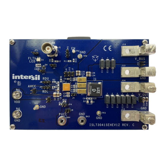
Page 4: Board Design
ISL73041SEHEV1Z Evaluation Board Manual Board Design Figure 2. Evaluation Board (Top) Figure 3. Evaluation Board (Bottom) R34UZ0012EU0101 Rev.1.01 Page 4 Jun 21, 2023... -
Page 5: Layout Guidelines
ISL73041SEHEV1Z Evaluation Board Manual Layout Guidelines PCB design files are available on the website to study or incorporate into your design. ▪ Use a multi-layer PCB with 2-ounce (70µm) copper outer layers to maximize PCB current capacitor and thermal handling. -
Page 6: Schematic Diagram
ISL73041SEHEV1Z Evaluation Board Manual Schematic Diagram UNNAMED_3_CONN2_I147_IN2 UNNAMED_3_SMCAP_I98_A UNNAMED_3_ISL73041SEH_I4_15 UNNAMED_3_CONN2_I40_IN2 UNNAMED_3_ISL73041SEH_I4_1 UNNAMED_3_ISL73041SEH_I4_8 UNNAMED_3_SMRES_I15_B UNNAMED_3_CONN2_I33_IN2 UNNAMED_3_SMRES_I6_B UNNAMED_3_NCHANNEL_I135_D UNNAMED_3_SMRES_I5_B Figure 4. ISL73041SEHEV1Z Board Schematics R34UZ0012EU0101 Rev.1.01 Page 6 Jun 21, 2023... -
Page 7: Bill Of Materials
ISL73041SEHEV1Z Evaluation Board Manual Bill of Materials Reference Designator Description Manufacturer Manufacturer Part PWB-PCB, ISL73041SEHEV1Z, REVC, Imagineering Inc ISL73041SEHEV1ZREVCPCB ROHS CAP, SMD, 0805, 1.0µF, C4, C7 C2012X7R1E105K 25V, 10%, X7R, ROHS C24, C26, C28, C30, CAP, SMD, 1206, 4.7µF, C3216X7R1E475K... - Page 8 ISL73041SEHEV1Z Evaluation Board Manual Reference Designator Description Manufacturer Manufacturer Part CONN-HEADER, 1×2, JP1, JP4 RETENTIVE, 2.54mm, BERG/FCI 69190-202HLF 0.230×0.120, RoHS CONN-HEADER, TH, 2×1, J1, J2, J3, J4, J6, J7, J8, BRKAWY, 0.100inCENTER, Samtec TSW-102-08-F-S J9, J10, J11, J12 0.230×0.200in, ROHS LED, SMD, 3×2.5mm, 4P,...
-
Page 9: Board Layout
DO NOT POPULATE OR PURCHASE DO NOT POPULATE OR D2 (B120B) PURCHASE DO NOT POPULATE OR L1 (XAL1580-612MEB) PURCHASE Board Layout Figure 5. ISL73041SEHEV1Z Top Assembly Layer Figure 6. ISL73041SEHEV1Z Bottom Assembly Layer R34UZ0012EU0101 Rev.1.01 Page 9 Jun 21, 2023... - Page 10 ISL73041SEHEV1Z Evaluation Board Manual Figure 7. ISL73041SEHEV1Z Layer 1 Figure 8. ISL73041SEHEV1Z Layer 2 R34UZ0012EU0101 Rev.1.01 Page 10 Jun 21, 2023...
- Page 11 ISL73041SEHEV1Z Evaluation Board Manual Figure 9. ISL73041SEHEV1Z Layer 3 Figure 10. ISL73041SEHEV1Z Layer 4 R34UZ0012EU0101 Rev.1.01 Page 11 Jun 21, 2023...
-
Page 12: Typical Performance Curves
ISL73041SEHEV1Z Evaluation Board Manual Typical Performance Curves LG to UG Dead Time (ns) UG to LG Dead Time (ns) LG to UG Dead Time (ns) UG to LG Dead Time (ns) RDU = RDL Resistance (kΩ) RDU = RDL Resistance (kΩ) Figure 11. - Page 13 IMPORTANT NOTICE AND DISCLAIMER RENESAS ELECTRONICS CORPORATION AND ITS SUBSIDIARIES (“RENESAS”) PROVIDES TECHNICAL SPECIFICATIONS AND RELIABILITY DATA (INCLUDING DATASHEETS), DESIGN RESOURCES (INCLUDING REFERENCE DESIGNS), APPLICATION OR OTHER DESIGN ADVICE, WEB TOOLS, SAFETY INFORMATION, AND OTHER RESOURCES “AS IS” AND WITH ALL FAULTS, AND DISCLAIMS ALL WARRANTIES, EXPRESS OR IMPLIED, INCLUDING, WITHOUT LIMITATION, ANY IMPLIED WARRANTIES OF MERCHANTABILITY, FITNESS FOR A PARTICULAR PURPOSE, OR NON-INFRINGEMENT OF THIRD PARTY INTELLECTUAL PROPERTY RIGHTS.
Need help?
Do you have a question about the ISL73041SEHEV1Z and is the answer not in the manual?
Questions and answers