Table of Contents
Advertisement
Quick Links
ISL73847SEHDEMO6Z
The ISL73847SEHDEMO6Z demonstration board
demonstrates the performance of two
dual-phase buck controller, four ISL73041SEH GaN
half-bridge drivers, and twelve ISL70020SEH 40V
GaN FETs in a 4-phase, 100A configuration. It is
designed for the VERSAL VC1902 VCCINT core rail.
The evaluation board is designed for a 5V PVIN
power rail and an auxiliary VDD supply for the
controller/driver VDD and on-board clock generator
circuits.
R34UZ0028EU0100 Rev.1.00
Jun 6, 2024
Features
ISL73847SEH
▪ On-board 2MHz clock generator for
▪ Power-Good (PG) LED indicator
▪ Integrated LDO (VCC)
▪ Load-line DROOP regulation
▪ Differential remote sensing
Specifications
▪ Buck power supply input (PVIN): 5V, ±5%
▪ Analog Supply input (VDD)
▪ Preset output voltage (no-load): 0.809V
▪ Preset Switching Frequency: 1MHz
▪ Maximum output current: 100A (25A/phase)
▪ Preset DROOP regulation: 2.6%
▪ Number of Board Layers: 8
▪ PCB Thickness: 2oz outer, 1oz inner
Demonstration Board Manual
synchronization
• 5V to 13.2V when clocks come from an off-board
external clock
• 9V to 13.2V when using the on-board clock
generator circuit
© 2024 Renesas Electronics
Page 1
Advertisement
Table of Contents

Related Manuals for Intersil ISL73847SEHDEMO6Z


Summary of Contents for Intersil ISL73847SEHDEMO6Z
- Page 1 Demonstration Board Manual ISL73847SEHDEMO6Z Features The ISL73847SEHDEMO6Z demonstration board demonstrates the performance of two ISL73847SEH ▪ On-board 2MHz clock generator for dual-phase buck controller, four ISL73041SEH GaN synchronization half-bridge drivers, and twelve ISL70020SEH 40V ▪ Power-Good (PG) LED indicator GaN FETs in a 4-phase, 100A configuration. It is ▪...
- Page 2 ISL73847SEHDEMO6Z Demonstration Board Manual VBUS Current Feedback Remote Voltage Feedback VOUT Half Bridge Driver ISL73041SEH VFB- PWM1 VREF ISEN1+ ISEN1- 2ph PWM Controller DROOP ISL73847 (Master) ISEN2+ VFB+ VBUS ISEN2- COMP PWM2 SYNC-I IMON Half Bridge Driver ISL73041SEH VBUS External Clock...
-
Page 3: Table Of Contents
ISL73847SEHDEMO6Z Demonstration Board Manual Contents Functional Description ..............4 Operating Range . -
Page 4: Functional Description
4-phase operation. Each phase delivers 25A RMS for a total 100A solution. Operating Range The ISL73847SEHDEMO6Z evaluation board requires two supply rails to operate properly. One rail for the two ISL73847SEH controller’s analog supply input, the four ISL73041SEH GaN half-bridge drivers, and clock generator circuits (VDD). -
Page 5: Quick-Start Guide
ISL73847SEHDEMO6Z Demonstration Board Manual To connect two ISL73847SEH controllers for a 4-phase configuration, use the following connections. ▪ For 90° phase shifted operation in a 4-phase Buck, an external Clock at twice the switching frequency with 50% duty cycle and its complimentary is necessary. See On-Board Clock Generator for Synchronization generating the clock and complementary signal for this demonstration board. -
Page 6: On-Board Clock Generator For Synchronization
ISL73847SEHDEMO6Z Demonstration Board Manual On-Board Clock Generator for Synchronization The ISL73847SEHDEMO6Z is designed with 1MHz switching frequency, therefore a 2MHz clock is needed. For proper 4-phase 90° phase shifted operation, the ISL73847SEHDEMO6Z uses an external clock synchronization circuit to output complimentary clocks on the SYNC-I pins of the ISL73847SEH controller. The external clock solution is implemented with an ISL78841ASRH current mode PWM controller. -
Page 7: Increasing The Maximum Output Current
Note: The dissipative elements in the power stage (GaN FETs and inductor) see a higher temperature rise due to the increased load current. 1. Operation of 140A on the ISL73847SEHDEMO6Z is recommended only for low duty cycle transient durations. If the customer requires 140A continuous operation, Renesas recommends using a separate PCB design to accommodate more GaN FETs in parallel and increase the number of PCB layers to manage the extra current. -
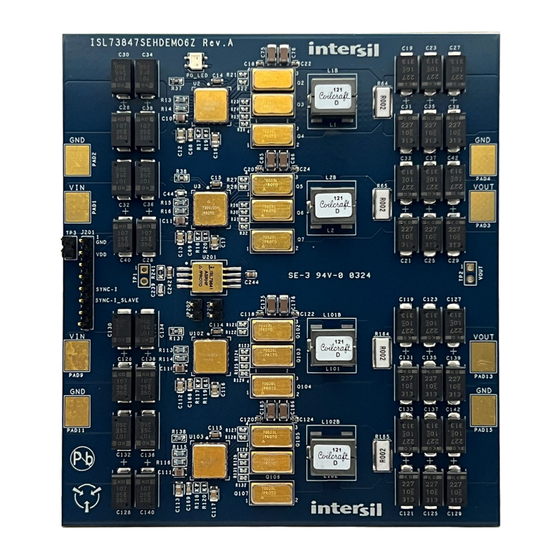
Page 8: Board Design
ISL73847SEHDEMO6Z Demonstration Board Manual Board Design Figure 4. ISL73847SEHDEMO6Z Evaluation Board (Top) R34UZ0028EU0100 Rev.1.00 Page 8 Jun 6, 2024... - Page 9 ISL73847SEHDEMO6Z Demonstration Board Manual Figure 5. ISL73847SEHDEMO6Z Evaluation Board (Bottom) R34UZ0028EU0100 Rev.1.00 Page 9 Jun 6, 2024...
-
Page 10: Schematic Diagrams
ISL73847SEHDEMO6Z Demonstration Board Manual Schematic Diagrams UNNAMED_1_SMRES_I342_A UNNAMED_1_ISL73041SEH_I277_15 UNNAMED_1_ISL73041SEH_I199_15 UNNAMED_1_NCHANNEL_I347_D UNNAMED_1_SMRES_I346_A UNNAMED_1_SMRES_I345_A Figure 6. ISL73847SEHDEMO6Z Schematic (Phases 1 & 2) R34UZ0028EU0100 Rev.1.00 Page 10 Jun 6, 2024... - Page 11 ISL73847SEHDEMO6Z Demonstration Board Manual UNNAMED_3_ISL73041SEH_I55_15 UNNAMED_3_ISL73041SEH_I94_15 Figure 7. ISL73847SEHDEMO6Z Schematic (Phases 3 & 4) R34UZ0028EU0100 Rev.1.00 Page 11 Jun 6, 2024...
- Page 12 FROM INPUT CAPS PHASE 3 FROM INPUT CAPS PHASE 4 DRAWN BY: TIM KLEMANN RELEASED BY: INPUT PHASES 1 TO 4 UPDATED BY: TIM KLEMANN Figure 8. ISL73847SEHDEMO6Z Schematic (Input Phases 1 to 4) R34UZ0028EU0100 Rev.1.00 Page 12 Jun 6, 2024...
- Page 13 ISL73847SEHDEMO6Z Demonstration Board Manual Figure 9. ISL73847SEHDEMO6Z Schematic (Output Phases 1 to 4 ) R34UZ0028EU0100 Rev.1.00 Page 13 Jun 6, 2024...
-
Page 14: Bill Of Materials
UNNAMED_6_ISL7884XA_I29_4 RTCT VSSP ISL70040SEHL/PROTO ISL78841ASRHF/PROTO J201 SYNC-I SYNC-I_SLAVE JP201 UNNAMED_6_JUMPER2_I36_IN1 CONN-1X8 Figure 10. ISL73847SEHDEMO6Z Schematic (Clock Synchronization Circuit) Bill of Materials Ref Des Description Manufacturer Part Number Multilayer Cap, 4700PF, 10%, Kemet C0603C472K3RAC7867 25V, 0603 C12, C13, C16, C17, C112, Multilayer Cap, 1µF, 10%, 25V,... - Page 15 ISL73847SEHDEMO6Z Demonstration Board Manual Ref Des Description Manufacturer Part Number Multilayer Cap (Automotive), C248 Kemet C0603C360K5HACAUTO 36pF, 10%, 50V, 0603 CERAMIC CHIP CAP C249, C252 (Automotive AEC-Q200), 4.7µF, Kemet C0805C475K3RACAUTO 10%, 25V, 0805 Ceramic Chip Cap, 1µF, 10%, C251 Murata...
- Page 16 ISL73847SEHDEMO6Z Demonstration Board Manual Ref Des Description Manufacturer Part Number Shielded Power Inductor (RoHS L1, L2, L101, L102 Compliant), 120nH, 10%, 86A, CoilCraft SLR1070-121KE (Do Not Populate) 4mm×4mm L1B, L2B, L101B, L102B Shielded Power Inductor, DNP, CoilCraft XAL1010-DNP 20%, SMD...
- Page 17 ISL73847SEHDEMO6Z Demonstration Board Manual Ref Des Description Manufacturer Part Number R34, R103, R105, R112, Metal Film Chip Resistor (Do Not Various Generic R134, R246 Populate), DNP, 1%, 0603 R4, R35, R36, R104, R135, Film Chip Resistor, 100k, 1%, Stackpole RMCF0603FT100K...
-
Page 18: Board Layout
ISL73847SEHDEMO6Z Demonstration Board Manual Board Layout Figure 11. Silkscreen Top Layer R34UZ0028EU0100 Rev.1.00 Page 18 Jun 6, 2024... - Page 19 ISL73847SEHDEMO6Z Demonstration Board Manual Figure 12. Top Layer R34UZ0028EU0100 Rev.1.00 Page 19 Jun 6, 2024...
- Page 20 ISL73847SEHDEMO6Z Demonstration Board Manual Figure 13. Layer 2 R34UZ0028EU0100 Rev.1.00 Page 20 Jun 6, 2024...
- Page 21 ISL73847SEHDEMO6Z Demonstration Board Manual Figure 14. Layer 3 R34UZ0028EU0100 Rev.1.00 Page 21 Jun 6, 2024...
- Page 22 ISL73847SEHDEMO6Z Demonstration Board Manual Figure 15. Layer 4 R34UZ0028EU0100 Rev.1.00 Page 22 Jun 6, 2024...
- Page 23 ISL73847SEHDEMO6Z Demonstration Board Manual Figure 16. Layer 5 R34UZ0028EU0100 Rev.1.00 Page 23 Jun 6, 2024...
- Page 24 ISL73847SEHDEMO6Z Demonstration Board Manual Figure 17. Layer 6 R34UZ0028EU0100 Rev.1.00 Page 24 Jun 6, 2024...
- Page 25 ISL73847SEHDEMO6Z Demonstration Board Manual Figure 18. Layer 7 R34UZ0028EU0100 Rev.1.00 Page 25 Jun 6, 2024...
- Page 26 ISL73847SEHDEMO6Z Demonstration Board Manual Figure 19. Bottom Layer R34UZ0028EU0100 Rev.1.00 Page 26 Jun 6, 2024...
- Page 27 ISL73847SEHDEMO6Z Demonstration Board Manual Figure 20. Silkscreen Bottom Layer R34UZ0028EU0100 Rev.1.00 Page 27 Jun 6, 2024...
-
Page 28: Typical Performance Graphs
ISL73847SEHDEMO6Z Demonstration Board Manual Typical Performance Graphs Unless otherwise noted, V = 12V, P = 5V = 0.807V; L = 120nH per phase, C = 1.54mF per phase, OUT(no-load) = 47nF, C = 100nF, R = 392Ω, R = 43.2kΩ, C = 22nF, C = 4.7nF, R... - Page 29 IMPORTANT NOTICE AND DISCLAIMER RENESAS ELECTRONICS CORPORATION AND ITS SUBSIDIARIES (“RENESAS”) PROVIDES TECHNICAL SPECIFICATIONS AND RELIABILITY DATA (INCLUDING DATASHEETS), DESIGN RESOURCES (INCLUDING REFERENCE DESIGNS), APPLICATION OR OTHER DESIGN ADVICE, WEB TOOLS, SAFETY INFORMATION, AND OTHER RESOURCES “AS IS” AND WITH ALL FAULTS, AND DISCLAIMS ALL WARRANTIES, EXPRESS OR IMPLIED, INCLUDING, WITHOUT LIMITATION, ANY IMPLIED WARRANTIES OF MERCHANTABILITY, FITNESS FOR A PARTICULAR PURPOSE, OR NON-INFRINGEMENT OF THIRD-PARTY INTELLECTUAL PROPERTY RIGHTS.
Need help?
Do you have a question about the ISL73847SEHDEMO6Z and is the answer not in the manual?
Questions and answers