
Related Manuals for Intersil ISL71026MEVAL1Z


Summary of Contents for Intersil ISL71026MEVAL1Z
- Page 1 ISL71026MEVAL1Z User’s Manual: Evaluation Board High Reliability Space Rev 0.00 May 2017...
-
Page 2: Ordering Information
The ISL71026MEVAL1Z board was designed to provide a quick and easy method for evaluating the ISL71026M 3.3V CAN transceiver. This device is a unique IC. Using this evaluation board properly requires a thorough knowledge of the operation of the IC. -
Page 3: Specifications
• CAN bus termination resistance of 60Ω across the CANH and CANL differential signal lines • Board temperature: +25°C Tx DATA IN CANH CANH CANL CANL 0.1µF µController ISL71026M Rx DATA OUT Figure 1.1 ISL71026MEVAL1Z Block Diagram UG121 Rev.0.00 Page 2 of 20 May 3, 2017... -
Page 4: Functional Description
2. Functional Description Functional Description The ISL71026MEVAL1Z evaluation board provides easy access to the pins of the ISL71026M IC and convenient connectors/test points for connecting test equipment. The schematic, bill of materials, and top silkscreen for the board are available in “PCB Layout Guidelines”... -
Page 5: Test Points
ISL71026MEVAL1Z 2. Functional Description 2.3.1 D Pin The D pin is the digital input to the driver of the transceiver. A digital bit pattern is applied at this pin. A logic 1 on the D pin puts the CANH and CANL differential pins in the recessive state. A logic 0 on the D pin, puts the CANH and CANL differential pins in the dominant state. - Page 6 ISL71026MEVAL1Z 2. Functional Description Board Component Definitions Designator Description ISL71026M TSSOP IC VCC power supply connection (nominal 3.3V Ground connection 9-pin male D-SUB connector (used to connect to another CAN evaluation board) Not populated - jumper on RS pin to connect mechanical potentiometer Jumper on the RS pin to connect it to VCC (a jumper installed at this location will put the transceiver in listen mode).
- Page 7 ISL71026MEVAL1Z 2. Functional Description FUNCTION GENERATOR 0V to 3.3V OSCILLOSCOPE 125kHz SQUARE WAVE 50Ω CANH CANL TP11 LOOP TP13 CANL CANH CONNECT PROBES AT THE FOLLOWING TEST POINTS ON THE EVALUATION BOARD DC POWER SUPPLY +3.3V Figure 2.1 Basic Evaluation Test Setup Block Diagram (Measuring Propagation Delay, Skew, and Rise/Fall Time) UG121 Rev.0.00...
- Page 8 ISL71026MEVAL1Z 3. Using the Board to Measure Propagation Delay, Skew, and Rise/Fall Time Using the Board to Measure Propagation Delay, Skew, and Rise/Fall Time Refer to Figure 2.1 on page Lab Equipment The equipment, external supplies, and signal sources needed to operate the board: •...
- Page 9 ISL71026MEVAL1Z 3. Using the Board to Measure Propagation Delay, Skew, and Rise/Fall Time (8) In fast speed mode (RS = 0V): • t should be around 75ns and no greater than 150ns. • t should be around 80ns and no greater than 155ns.
- Page 10 ISL71026MEVAL1Z 4. Waveforms Waveforms Figure 4.1 Oscilloscope Plot (Fast Speed) Waveforms and Measurements Figure 4.2 Oscilloscope Plot (Medium Speed) Waveforms and Measurements UG121 Rev.0.00 Page 9 of 20 May 3, 2017...
- Page 11 ISL71026MEVAL1Z 4. Waveforms Figure 4.3 Oscilloscope Plot (Slow Speed) Waveforms and Measurements UG121 Rev.0.00 Page 10 of 20 May 3, 2017...
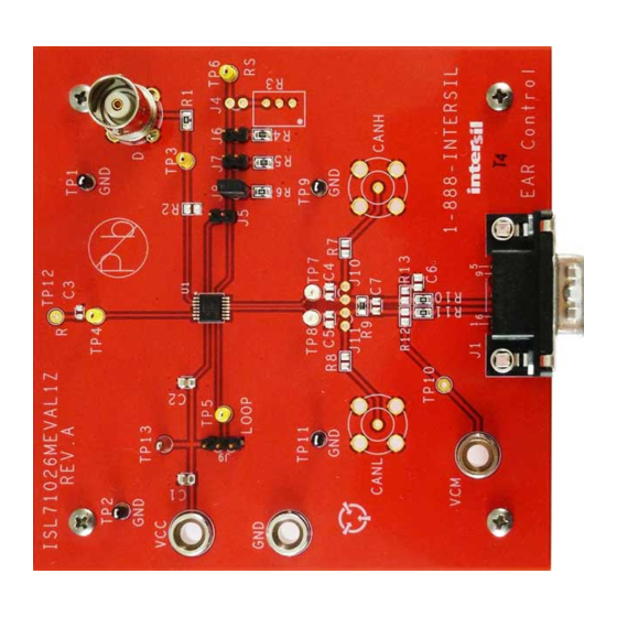
- Page 12 ISL71026MEVAL1Z 5. PCB Layout Guidelines PCB Layout Guidelines Evaluation Board Figure 5.1 ISL71026MEVAL1Z Evaluation Board UG121 Rev.0.00 Page 11 of 20 May 3, 2017...
- Page 13 Schematic Figure 5.2 ISL71026MEVAL1Z Circuit Schematic...
-
Page 14: Bill Of Materials
Bill of Materials Reference Qty Units Designator Description Manufacturer Part Number SEE LABEL - PWB-PCB, ISL71026MEVAL1Z, Rev A, ROHS Imagineering Inc ISL71026MEVAL1ZREVAPCB RENAME BOARD CAP, SMD, 0805, 0.1µF, 50V, 10%, X7R, ROHS KEMET C0805C104K5RACTU CAP, SMD, 0805, 10µF, 25V, 10%, X5R, ROHS C2012X5R1E106K CONN - BNC, RECEPTACLE, TH, 4 POST, 50Ω,... -
Page 15: Board Layout
ISL71026MEVAL1Z 5. PCB Layout Guidelines Board Layout Figure 5.3 Top Layer Figure 5.4 Bottom Layer Figure 5.5 Top Layer Silk Screen UG121 Rev.0.00 Page 14 of 20 May 3, 2017... -
Page 16: Typical Performance Curves
ISL71026MEVAL1Z 6. Typical Performance Curves Typical Performance Curves Unless noted: VCC = 3.3V, D = 125kHz, Square Wave, 0 to VCC, 50% Duty Cycle, t ≤6ns, T = +25°C = 10kΩ, R = 60Ω = GND, R = 60Ω CANH - CANL CANH - CANL TIME (1µs/DIV) - Page 17 ISL71026MEVAL1Z 6. Typical Performance Curves 1200 = 10kΩ, R = 60Ω = 10kΩ, R = 60Ω L TO H, V = 3V L TO H, V = 3V 1000 L TO H, V = 3.6V H TO L, V = 3.6V L TO H, V = 3.6V...
-
Page 18: Revision History
ISL71026MEVAL1Z 7. Revision History Revision History Description Rev. Date Page Summary 0.00 May 3, 2017 — Initial release UG121 Rev.0.00 Page 17 of 20 May 3, 2017... -
Page 19: Corporate Headquarters
IMPORTANT NOTICE AND DISCLAIMER RENESAS ELECTRONICS CORPORATION AND ITS SUBSIDIARIES (“RENESAS”) PROVIDES TECHNICAL SPECIFICATIONS AND RELIABILITY DATA (INCLUDING DATASHEETS), DESIGN RESOURCES (INCLUDING REFERENCE DESIGNS), APPLICATION OR OTHER DESIGN ADVICE, WEB TOOLS, SAFETY INFORMATION, AND OTHER RESOURCES “AS IS” AND WITH ALL FAULTS, AND DISCLAIMS ALL WARRANTIES, EXPRESS OR IMPLIED, INCLUDING, WITHOUT LIMITATION, ANY IMPLIED WARRANTIES OF MERCHANTABILITY, FITNESS FOR A PARTICULAR PURPOSE, OR NON-INFRINGEMENT OF THIRD PARTY INTELLECTUAL PROPERTY RIGHTS. - Page 20 ISL71026MEVAL1Z UG121...
- Page 21 Mouser Electronics Authorized Distributor Click to View Pricing, Inventory, Delivery & Lifecycle Information: Renesas Electronics ISL71026MEVAL1Z...
Need help?
Do you have a question about the ISL71026MEVAL1Z and is the answer not in the manual?
Questions and answers