Advertisement
Quick Links
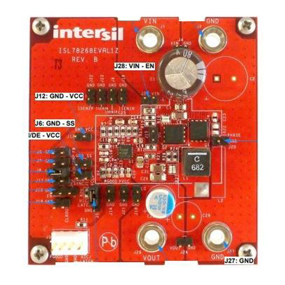
ISL78268EVAL1Z
Introduction
ISL78268 is an automotive grade synchronous buck controller
with the 2-A sourcing/3-A sinking Integrated MOSFET Drivers.
The device supports the wide input supply voltage range of 5V
to 55V for full operation and protected up to 60V when not
switching. The ISL78268EVAL1Z is a fully configured buck
converter evaluation board with ISL78268, MOSFETS, an
inductor, current sense resistors and other necessary
components. The evaluation board has been designed to
quickly evaluate the various features and performance of the
ISL78268.
Specification (Default Setting)
• V
= 14V to 55V
IN
• V
= 12V
OUT
• V
overvoltage protection = 58V (rising threshold to trigger
IN
hiccup or latch-off)
• Output overcurrent limit 1 (OC1: cycle-by-cycle) = 9.3A
• Output overcurrent limit 2 (OC2: hiccup/latch-off) = 12.4A
• Output average constant current limit = 4.05A (if activated)
• Switching frequency = 300kHz
• Peak efficiency > 95% (V
IN
IMON/DE:
V
= FORCED PWM MODE
CC
W/O ACL
GND = DE MODE W/O ACL
0V~2V = DE MODE W/ ACL
HIC/LATCH : CONNECT TO
V
FOR LATCH-OFF
CC
MODE OR GND FOR
HICCUP MODE
July 7, 2014
AN1946.0
Evaluation
Board User Guide
= 15V/ I
= 4A)
OUT
J12: VCC
J1: VIN
J28
J4
VCC
J2: GND
J10: EN
EN
VCC
J11: IMON/DE
IMON/DE
J8: IMON/DE
J17: FSYNC
FSYNC
ISL78268
PLL_COMP
J7: COMP
COMP
SLOPE
VCC
J13: HIC/LATCH
HIC/LATCH
J6: SS
SS
SGND
FIGURE 1. ISL78268EVAL1Z BLOCK DIAGRAM
1
CAUTION: These devices are sensitive to electrostatic discharge; follow proper IC Handling Procedures.
Key Features
• Wide operational input voltage range up to 55V (switching),
withstand 60V (non-switching)
• Average output constant current limiting
• Selectable diode emulation mode or forced PWM mode
• Selectable switching clock source: internal or external
• Low shutdown current: I
• Selectable latch-off or hiccup mode fault response
• Comprehensive fault protections:
- Input and output overvoltage protection
- Cycle-by-cycle overcurrent limit (OC1) and
protection (OC2)
- Average current overcurrent protection
- Over-temperature protection
• Monitor test points for key signals
Reference
•
ISL78268
Datasheet
Ordering Information
PART NUMBER
ISL78268EVAL1Z
J9
VIN
ISEN1P
ISEN1N
J16
PVCC
BOOT
UG
J15
PH
LG
J18
ISEN2P
J22
ISEN2N
J23
FB
VCC
PGOOD
CLKOUT
PGND
|
1-888-INTERSIL or 1-888-468-3774
Intersil (and design) is a trademark owned by Intersil Corporation or one of its subsidiaries.
All other trademarks mentioned are the property of their respective owners.
Application Note 1946
<10µA
Q
DESCRIPTION
ISL78268 Evaluation Board
J21: PVCC
J20: PHASE
J26: VOUT
J24
J27: GND
J5: FB
J14: PGOOD
J19: CLKOUT
Copyright Intersil Americas LLC 2014. All Rights Reserved
Advertisement

Related Manuals for Intersil ISL78268EVAL1Z


Summary of Contents for Intersil ISL78268EVAL1Z
- Page 1 CAUTION: These devices are sensitive to electrostatic discharge; follow proper IC Handling Procedures. 1-888-INTERSIL or 1-888-468-3774 Copyright Intersil Americas LLC 2014. All Rights Reserved AN1946.0 Intersil (and design) is a trademark owned by Intersil Corporation or one of its subsidiaries. All other trademarks mentioned are the property of their respective owners.
-
Page 2: Functional Description
FSYNC pin. The external clock frequency range will be 50kHz to 1.1MHz. • The output voltage of ISL78268EVAL1Z is fixed at 12V in default setting. This can be changed by replacing feedback resistor R . - Page 3 Application Note 1946 ISL78268EVAL1Z Evaluation Board J1: VIN J2: GND J28: VIN - EN J12: GND - VCC J6: GND - SS J11: IMON/DE - VCC J20: PHASE- GND J5 GND - FB J7: GND - COMP J8: GND - IMONDE...
- Page 4 Application Note 1946 Connector/Monitor-pin Description Table 1 shows the jumper/terminal configuration of the ISL78268EVAL1Z. TABLE 1. ISL78268EV1ZB CONNECTOR/MONITOR-PIN DESCRIPTION CONNECTOR/ TERMINAL SIGNAL NAME DESCRIPTIONS Positive input terminal of the system. Negative input terminal of the system (ground). J3-1 PGOOD PGOOD monitor pin...
-
Page 5: Quick Start Guide
Application Note 1946 TABLE 1. ISL78268EV1ZB CONNECTOR/MONITOR-PIN DESCRIPTION (Continued) CONNECTOR/ TERMINAL SIGNAL NAME DESCRIPTIONS ISEN2P - GND Test point to monitor ISEN2P waveform (Do Not short with jumper). For accurate monitoring of the voltage difference between ISEN2P and ISEN2N, place a differential probe between Pin 2 of J22 and Pin 2 of J23. ISEN2N - GND Test point to monitor ISEN2N waveform (Do Not short with jumper). - Page 6 Application Note 1946 1.2. Functional Confirmation and Measurement pin voltage reaches 1.6V, ACL will be triggered. While in ACL, On-duty becomes shorter and output voltage drops to • Normal Operation with DE Mode operation at light keep the output current at the same level. load.
- Page 7 Application Note 1946 TABLE 2. ISL78268EV1Z MODE SETTING EXAMPLE (Continued) SETTING EXAMPLE INTERNAL CLOCK/ SYNC WITH EXT HICCUP/ INTERNAL CLOCK/ INTERNAL CLOCK/ SYNC WITH EXT CLOCK/ DE MODE/ HICCUP/ LATCH-OFF/ CLOCK/ HICCUP/ LATCH-OFF/ CONNECTOR/ ACL ENABLED DE MODE/ FORCED PWM/ FORCED PWM/ DE MODE/ TERMINAL...
- Page 8 ISL78268EVAL1Z Schematic AON6246 VOUT PHASE +12V 0.005 0.005 4.7µH VOUT AON6246 100pF 220pF 100pF 100pF 220pF 100pF VOUT 0.1µF 0.022µF 100pF PVCC 6800pF 27.4k 0.22µF SLOPE BOOT PHASE COMP COMP ISL78268ARZ IMON/DE PVCC 0.01µF IMON/DE PVCC PGOOD PGOOD PGND 130k CLKOUT 0.1µF...
- Page 9 TABLE 3. ISL78268EVAL1Z BUILD OF MATERIALS LIST COMPONENT ACCURACY REFERENCE DESIGNATOR QTY UNITS TYPE VALUE RATING TYPE SIZE OTHER DESCRIPTION MANUFACTURER MANUFACTURER PART ISL78268EVAL1Z REV. B PWB-PCB, IMAGINEERING INC ISL78268EVAL1ZREVBPCB ISL78268EVAL1Z-REVB, ROHS Capacitor, 1.0µF 0603 SMD, ROHS C1608X7R1C105K Ceramic Capacitor, 4.7µF...
- Page 10 TABLE 3. ISL78268EVAL1Z BUILD OF MATERIALS LIST (Continued) COMPONENT ACCURACY REFERENCE DESIGNATOR QTY UNITS TYPE VALUE RATING TYPE SIZE OTHER DESCRIPTION MANUFACTURER MANUFACTURER PART C2,C29 Capacitor Not Placed. Place-holder for Placed additional input and output cap Inductor 6.8µH 7.5x7.2 SMD, 17.84mΩ, ROHS...
- Page 11 TABLE 3. ISL78268EVAL1Z BUILD OF MATERIALS LIST (Continued) COMPONENT ACCURACY REFERENCE DESIGNATOR QTY UNITS TYPE VALUE RATING TYPE SIZE OTHER DESCRIPTION MANUFACTURER MANUFACTURER PART Connector, 1x4, SOLID, VERTICAL, FRICTION MOLEX 22-11-2042 Header 2.54mm LOCK, GOLD pitch J10, J13 Connector, 1x3,...
- Page 12 Application Note 1946 Layout Pattern (4-layers) FIGURE 5. SILK PATTERN (TOP) FIGURE 6. TOP LAYER FIGURE 7. LAYER 2 FIGURE 8. LAYER 3 FIGURE 10. SILK PATTERN (BOTTOM) FIGURE 9. BOTTOM LAYER Submit Document Feedback AN1946.0 July 7, 2014...
-
Page 13: Typical Performance Curves
Application Note 1946 Typical Performance Curves 12.30 12.25 12.20 12.15 = 15V = 24V 12.10 = 36V 12.05 = 55V = 55V 12.00 11.95 = 36V 11.90 = 24V = 15V 11.85 = 12V, T = +25°C 11.80 FIGURE 11. EFFICIENCY (AT +25°C): DE MODE, V = 12V, FIGURE 12. - Page 14 Application Note 1946 Typical Performance Curves (Continued) : 5V/DIV : 5V/DIV SS: 1V/DIV SS: 1V/DIV FB: 1V/DIV FB: 1V/DIV PH: 10V/DIV PH: 10V/DIV 500µs/DIV 500µs/DIV FIGURE 17. SOFT-START (NON-PREBIASED): DE MODE, V = 36V, FIGURE 18. SOFT-START (NON-PREBIASED): DE MODE, V = 36V, = 12V, I = 2.5A, L = 4.7µH, C...
- Page 15 CHANGE = 50% Intersil Corporation reserves the right to make changes in circuit design, software and/or specifications at any time without notice. Accordingly, the reader is cautioned to verify that the Application Note or Technical Brief is current before proceeding.
- Page 16 Mouser Electronics Authorized Distributor Click to View Pricing, Inventory, Delivery & Lifecycle Information: Intersil ISL78268EVAL1Z...
Need help?
Do you have a question about the ISL78268EVAL1Z and is the answer not in the manual?
Questions and answers