
Related Manuals for Phytec L-820e.A2


Summary of Contents for Phytec L-820e.A2
- Page 1 L-820e.A2 phyBOARD-Segin i.MX 6UL/ULL Hardware Manual A product of PHYTEC Technology Holding Company...
- Page 2 L-820e.A2 phyBOARD-Segin i.MX 6UL/ULL Hardware Manual L-820e.A2 phyBOARD-Segin i.MX 6UL/ULL Hardware Manual Document Title L-820e.A2 phyBOARD-Segin i.MX 6UL/ULL Hardware Manual Article Number L-820e.A2 Release Date 18.07.2022 SOM Prod. No. PCM-063 SOM PCB No. 1468.x SBC Prod. No.: PB-02013-xxx CB PCB No.: ...
- Page 3 L-820e.A2 phyBOARD-Segin i.MX 6UL/ULL Hardware Manual © PHYTEC Messtecknik GmbH...
- Page 4 All phyBOARDs are rated for industry, cost-optimized, and offer long-term availability. The phyBOARD‑Segin i.MX 6UL/ULL is one of currently six industrial-grade carrier boards that are suitable for series production and that have been realized in accordance with PHYTEC's new SBCplus concept. It is an excellent example of this concept.
-
Page 5: Ordering Information
Modules (SOMs) that can be populated with different controllers and, hence, offers various functions and configurations. PHYTEC supports a variety of 8-/16- and 32-bit controllers in two ways: as the basis for Rapid Development Kits which serve as a reference and evaluation platform ®... - Page 6 Populated on the SOM / SBC With the purchase of a PHYTEC SOM / SBC, you will, in addition to our hardware and software possibilities, receive free obsolescence maintenance service for the hardware we provide. Our PCM (Product Change Management) team of developers is continuously processing all incoming PCNs (Product Change Notifications) from vendors and distributors concerning parts that are used in our products.
- Page 7 1.6 PHYTEC Documentation PHYTEC will provide a variety of hardware and software documentation for all of our products. This includes any or all of the following: •...
- Page 8 L-820e.A2 phyBOARD-Segin i.MX 6UL/ULL Hardware Manual After finishing the Quickstart Guide, we recommend working through the Development Environment Guide. This will give you a comprehensive overview of the features and functions of both the SOM and carrier board. © PHYTEC Messtecknik GmbH...
-
Page 9: Conventions, Abbreviations, And Acronyms
L-820e.A2 phyBOARD-Segin i.MX 6UL/ULL Hardware Manual 2 Conventions, Abbreviations, and Acronyms ® This hardware manual describes the PCM-063 System on Module in the following referred to as phyCORE -i.MX 6UL/ ® ULL. The manual specifies the phyCORE -i.MX 6UL/ULL's design and function. Precise specifications for the NXP®... - Page 10 L-820e.A2 phyBOARD-Segin i.MX 6UL/ULL Hardware Manual 2.2 Types of Signals Different types of signals are brought out at the phyCORE-Connector. The following table lists the abbreviations used to specify the type of a signal. TABLE 1: Signal Types used in this Manual...
- Page 11 L-820e.A2 phyBOARD-Segin i.MX 6UL/ULL Hardware Manual PCIe Output Differential line pairs 100 Ohm PCIe level output PCIe_O MIPI CSI‑2 Input Differential line pairs 100 Ohm MIPI CSI‑2 level input CSI‑2_I © PHYTEC Messtecknik GmbH...
-
Page 12: Abbreviations And Acronyms
Solder jumpers; these types of jumpers require solder equipment to remove and place. Solderless jumpers; these types of jumpers can be removed and placed by hand with no special tools. Printed circuit board. PHYTEC Display Interface; defined to connect PHYTEC display adapter boards, or custom adapters PHYTEC Extension Board PMIC Power management IC... - Page 13 L-820e.A2 phyBOARD-Segin i.MX 6UL/ULL Hardware Manual Real-time clock. Surface mount technology. ® System on Module; used in reference to the PCL-063 / phyCORE ‑i.MX 6UL/ULL module User button Sx (e.g. S1, S2, etc.) used in reference to the available user buttons, or DIP-Switches on the carrier board.
-
Page 14: Hardware Overview
The phyCORE‑i.MX 6UL/ULL (PCL-063) is a connector-less, BGA style System On Module (SOM) in a direct solder form factor. Unlike traditional Phytec SOM products that support high-density connectors, the PCL-063 SOM is directly soldered down to the phyBOARD‑Segin i.MX 6UL/ULL using Half-Hole Technology. This solution offers an ultra-low- cost Single Board Computer for the i.MX 6UL/ULL processor, while maintaining most of the advantages of the SOM... -
Page 15: Block Diagram
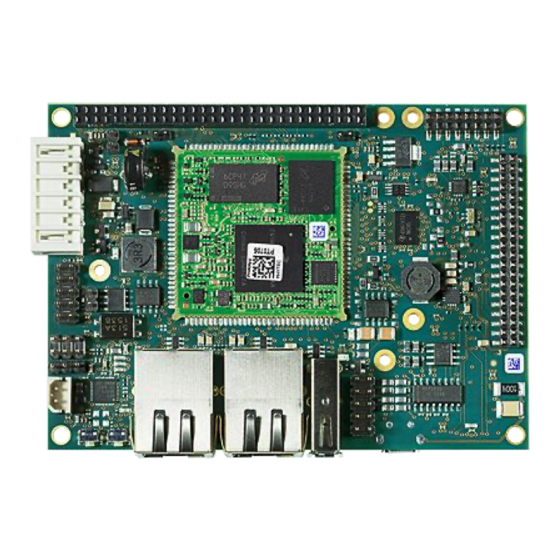
L-820e.A2 phyBOARD-Segin i.MX 6UL/ULL Hardware Manual 3.1.2 Block Diagram FIGURE 1: Block Diagram of the phyBOARD‑Segin i.MX 6UL/ULL © PHYTEC Messtecknik GmbH... - Page 16 L-820e.A2 phyBOARD-Segin i.MX 6UL/ULL Hardware Manual 3.1.3 View of the phyBOARD-Segin i.MX 6UL/ULL FIGURE 2: View of the phyBOARD‑Segin i.MX 6UL/ULL (top) © PHYTEC Messtecknik GmbH...
- Page 17 FIGURE 3: View of the phyBOARD‑Segin i.MX 6UL/ULL (bottom) 3.2 Accessing the phyBOARD-Segin i.MX 6UL/ULL Features PHYTEC phyBOARD‑Segin i.MX 6UL/ULL is fully equipped with all mechanical and electrical components necessary for a speedy and secure start-up. 3.3 Overview of the phyBOARD-Segin i.Mx 6UL/ULL Peripherals The phyBOARD‑Segin i.MX 6UL/ULL is depicted in...
- Page 18 L-820e.A2 phyBOARD-Segin i.MX 6UL/ULL Hardware Manual 3.3.1 Connectors and Pin Header The following table lists all available connectors on the phyBOARD‑Segin i.MX 6UL/ULL. View of the phyBOARD‑Segin i.MX 6UL/ULL (top) and View of the phyBOARD‑Segin i.MX 6UL/ULL (bottom) highlights the location of each connector for easy identification.
- Page 19 L-820e.A2 phyBOARD-Segin i.MX 6UL/ULL Hardware Manual A/V connector #2 (2×8 dual entry socket 2 mm pitch) Expansion connector (2×30 socket connector Expansion Connector (X16) 2 mm pitch) Mono Speaker output (2-pole Molex SPOX Audio Interface (X28 and X9) 2.5 mm pitch) Warning Ensure that all module connections must not exceed their expressed maximum voltage or current.
- Page 20 L-820e.A2 phyBOARD-Segin i.MX 6UL/ULL Hardware Manual 3.3.3 Buttons The phyBOARD-Segin i.MX 6UL/ULL is populated with two pushbuttons, one to reset the phyBOARD and another to power on and power off the NXP® Semiconductor i.MX 6UL/ULL CPU. View of the phyBOARD‑Segin i.MX 6UL/ULL (top) shows the location of the switches. Their function is listed in the table below: TABLE 5: phyBOARD-Segin i.MX 6UL/ULL Buttons Description...
-
Page 21: Power Supply
L-820e.A2 phyBOARD-Segin i.MX 6UL/ULL Hardware Manual Boot Selection Boot Mode (JP1) JTAG Mode Selection JTAG Interface CAN Termination Selection CAN Connectivity (X6, JP5) System Backup Voltage Selection Backup Voltage, RTC, and X3 Note Detailed descriptions of the assembled connectors, jumpers, and switches can be found in the following sections. - Page 22 L-820e.A2 phyBOARD-Segin i.MX 6UL/ULL Hardware Manual FIGURE 5: Power Supply Connectors(X2), Backup Voltage Connector (X3) Phoenix Contact 2-pole MINI COMBICON Base Strip (X2) The permissible input voltage is +5 V DC if your SBC is equipped with a 2-pole Phoenix Contact MINI COMBICON base strip.
- Page 23 L-820e.A2 phyBOARD-Segin i.MX 6UL/ULL Hardware Manual VCC3V3_PMOD +3.3 V power supply VCC_BL Backlight power supply (input voltage of power module) PMOD_PWRGOOD Power good signal (connected to reset nRESET_IN) nPMOD_PWRFAIL Power fail signal A detailed description of the Power Module for phyBOARDs including information on the minimum supply current can be found in the Application Guide for phyBOARD Expansion Boards (L-793e).
- Page 24 L-820e.A2 phyBOARD-Segin i.MX 6UL/ULL Hardware Manual The backup voltage source (either Gold cap at C1, or external battery via X3) supplies the external RTC at U2. Closing jumper JP7 connects the backup voltage source also to the backup voltage domain VDD_SNVS of the i.MX 6UL/ULL which supplies the RTC and some critical registers when the primary system power, VCC5V, is...
- Page 25 L-820e.A2 phyBOARD-Segin i.MX 6UL/ULL Hardware Manual TABLE 10: Pin Assignment of RS-232 /RS‑485 Interface Connector X5 Signal Signal X_UART5_RXD_RS232 X_UART5_RTS_RS232 X_UART5_TXD_RS232 X_UART5_CTS_RS232 X_UART5_RS485_A X_UART5_RS485_B An adapter cable is included in the phyBOARD‑Segin i.MX 6UL/ULL Kit to facilitate the use of the UART5 interface.
-
Page 26: Mac Address
MAC address. In order to guarantee that the MAC address is unique, all addresses are managed in a central location. Phytec has acquired a pool of MAC addresses. The MAC address of the phyBOARD‑Segin i.MX 6UL/ULL is located on the bar code sticker attached to the module. - Page 27 L-820e.A2 phyBOARD-Segin i.MX 6UL/ULL Hardware Manual FIGURE 9: USB Interfaces Connectors X8 and X7 LED D12 displays the status of USB_OTG1_VBUS and LED D11 indicates the status of X_USB_OTG2_VBUS (shown below). FIGURE 10: USB Host and OTG LEDs Two jumpers and a resistor allow configuring the USB1 interface according to your needs. Please refer to...
- Page 28 L-820e.A2 phyBOARD-Segin i.MX 6UL/ULL Hardware Manual FIGURE 11: Audio Interfaces at Connectors (X28 and X9) TABLE 12: Pin Assignment of Audio Connector X9 Signal Signal LINE_IN_L LINE_IN_R AGND AGND LINE_OUT_L LINE_OUT_R TABLE 13: Pin Assignment of Audio Connector X28 Signal...
- Page 29 L-820e.A2 phyBOARD-Segin i.MX 6UL/ULL Hardware Manual TABLE 14: Audio Codec Disable Jumper JP2 Mode Selection Description Audio reset signal (JP2 = 1+2) Audio codec normal operation JTAG mode (JP2 = 2+3) Audio codec disabled, JTAG interface can be used 3.4.6 CAN Connectivity (X6, JP5) ...
- Page 30 L-820e.A2 phyBOARD-Segin i.MX 6UL/ULL Hardware Manual TABLE 15: Pin Assignment of CAN Connector X6 Signal Signal X_CANL X_CANH Shield An adapter cable is included in the phyBOARD‑Segin i.MX 6UL/ULL Kit to facilitate the use of the CAN interface. The following figure shows the signal mapping of the adapter.
- Page 31 L-820e.A2 phyBOARD-Segin i.MX 6UL/ULL Hardware Manual FIGURE 13: SD/MM Card Interface at Connector X4 (backside) The phyBOARD-Segin i.MX 6UL/ULL provides a standard microSDHC card slot at X4 for connection to MMC/SD interface cards. It allows easy and convenient connection to peripheral devices such as SD- and MMC cards. Power to the SD interface is supplied by inserting the appropriate card into the MMC/SD connector, which features card detection, a lock mechanism, and a smooth extraction function by Push-in/Push-out of the card.
- Page 32 L-820e.A2 phyBOARD-Segin i.MX 6UL/ULL Hardware Manual FIGURE 15: Camera Interface (phyCAM-P) at Connector X12 The table below shows the pinout of the connector X12. PHYTEC Camera Connector X12 4. Only the i.MX 6UL/ULL microcontroller versions Y2, G2, and G3 are equipped with one parallel CMOS Sensor Interface (CSI) to process the signals from the parallel camera interface.
- Page 33 L-820e.A2 phyBOARD-Segin i.MX 6UL/ULL Hardware Manual FIGURE 16: Boot Mode Selection Jumper JP1 TABLE 17: Boot Jumper Configuration JP1 Boot Mode Description Boot mode 1 (JP1 = open) Boot from NAND Boot mode 2 (JP1 = closed) Boot from SD/MMC 1 3.4.10 CPU ON/OFF (S1) ...
- Page 34 L-820e.A2 phyBOARD-Segin i.MX 6UL/ULL Hardware Manual 3.4.11 System Reset Button (S2) The phyBOARD-Segin i.MX 6UL/ULL is equipped with a system reset button at S2. Pressing this button will toggle the X_nRESET_IN pin (X1-100) of the phyCORE SOM low, causing the module to reset. Additionally, the reset signal X_nRESET_OUT is generated on the module (X1-98) to also reset the peripherals on the carrier board.
-
Page 35: About This Section
L-820e.A2 phyBOARD-Segin i.MX 6UL/ULL Hardware Manual 4 System-Level Customizing 4.1 About this Section This section addresses advanced developers who want to design custom expansion boards or display adapters. It includes detailed information on the different interfaces and features of the phyBOARD-Segin i.MX 6UL/ULL at a system level. - Page 36 L-820e.A2 phyBOARD-Segin i.MX 6UL/ULL Hardware Manual X_GPIO5_1 3.3 V External RTC interrupt available on expansion connector X16 X_GPIO5_0 3.3 V Tamper pin on expansion connector X16 X_GPIO5_5 3.3 V Interrupt for AV adapter X_GPIO1_1 3.3 V Watchdog signal available on expansion connector X16 4.2.2 Soldering Jumpers Numerous jumpers and 0 Ohm resistors allow configuring the phyBOARD according to your needs.
- Page 37 L-820e.A2 phyBOARD-Segin i.MX 6UL/ULL Hardware Manual I2C Connectivity Changing the I C address of the touchscreen controller ABA_U1 J19, J20 Configuring the phyCAM-P control signals Configuring the CAM_CTRL Signals X_CAM_CTRL1 and X_CAM_CTRL2 J19, J20 Disabling the phyCAM-P bus transceiver Disabling the phyCAM-P Bus...
- Page 38 L-820e.A2 phyBOARD-Segin i.MX 6UL/ULL Hardware Manual AV-Adapter HDMI PEB-AV-01 HDMI Core 0x70 CEC Core 0x34 AV-Adapter Display PEB-AV-02 GPIO Expander 0x41 Evaluation Board PEB-EVAL-01 EEPROM 0x56 M2M Board PEB-C-01 GPIO Expander 0x20 GPIO Expander 0x21 GPIO Expander 0x22 4.2.4 USB OTG Connectivity ...
- Page 39 L-820e.A2 phyBOARD-Segin i.MX 6UL/ULL Hardware Manual 4.2.5.1 Configuring the CAM_CTRL Signals J19, J20 The different phyCAM-P camera modules offer various additional features such as I C address selection, strobe output, or trigger input to name a few. These are available via the CAM_CTRLx I/O pins. Jumpers J19 and J20 allow configuring the CAM_CTRLx I/Os according to the phyCAM-P camera module connected to X12.
- Page 40 L-820e.A2 phyBOARD-Segin i.MX 6UL/ULL Hardware Manual 4.2.5.2 Disabling the phyCAM-P Bus Transceiver J21 Jumper J21 allows disabling the phyCAM-P bus transceiver at U6. Closing J21 at 2+3 places both output ports of the transceiver into the high-impedance mode. TABLE 24: Disabling the phyCAM-P Bus Transceiver J21...
- Page 41 L-820e.A2 phyBOARD-Segin i.MX 6UL/ULL Hardware Manual TABLE 25: PHYTEC A/V Connector #1 (X14) Signal Name Type Description Ground X_LCD_D22_AV 3.3V LCD data 22 X_LCD_D23_AV 3.3 V LCD data 23 X_LCD_D12 3.3 V LCD data 12 X_LCD_D13 3.3 V LCD data 13 Ground X_LCD_D14 3.3 V...
- Page 42 L-820e.A2 phyBOARD-Segin i.MX 6UL/ULL Hardware Manual Ground X_LCD_D18_AV 3.3 V LCD data 18 X_LCD_D19_AV 3.3 V LCD data 19 X_LCD_D0 3.3 V LCD data 00 X_LCD_D1 3.3 V LCD data 01 Ground X_LCD_D2 3.3 V LCD data 02 X_LCD_D3 3.3 V LCD data 03 X_LCD_D4 3.3 V...
- Page 43 L-820e.A2 phyBOARD-Segin i.MX 6UL/ULL Hardware Manual Warning Please consider that the LCD data signals shown in the table above are boot configuration pins that must not be driven by any device on the baseboard during reset, to avoid accidental change of the boot configuration.
- Page 44 L-820e.A2 phyBOARD-Segin i.MX 6UL/ULL Hardware Manual TS_Y- 1.8 V Touch Y- VCC3V3 3.3 V 3.3 V power supply Ground X_I2C1_SCL 3.3 V I2C1 clock X_I2C1_SDA 3.3 V I2C1 data 9. Caution! The GPIO5 interface (GPIO5_0 to GPIO5_9) is multiplexed with the tamper detection inputs. These GPIOs can not be used as GPIO if the phyCORE-i.MX 6UL/ULL is equipped with the i.MX 6UL/ULL version G3.
- Page 45 L-820e.A2 phyBOARD-Segin i.MX 6UL/ULL Hardware Manual X_nRESET_OUT connected to X15 pin 8 X_LCD_RESET connected to X15 pin 8 4.2.6.2 Brightness The PWM signal at pin 38 allows changing the brightness of the display attached to the A/V connector. 4.2.6.3 I...
- Page 46 L-820e.A2 phyBOARD-Segin i.MX 6UL/ULL Hardware Manual TABLE 29: GPIOs available at A/V Connector X15 Pin # GPIO Name Default Usage Comment GPIO5_5 Can be used as A/V connector interrupt GPIO1_18 Warning The GPIO5 interface (GPIO5_0 to GPIO5_9) is multiplexed with the tamper detection inputs. Hence, GPIO5_5 is not available if the phyCORE-i.MX 6UL/ULL is equipped with the i.MX 6UL/ULL version G3.
- Page 47 L-820e.A2 phyBOARD-Segin i.MX 6UL/ULL Hardware Manual X_UART2_nCTS / 3.3 V ECSPI3 master output/slave input SPI3_MOSI X_UART2_RTS_B / 3.3 V ECSPI3 master input/slave output SPI3_MISO X_UART2_RX / 3.3 V ECSPI3 clock output SPI3_CLK Ground X_UART1_RX 3.3 V UART 1receive data (standard debug interface) X_I2C1_SDA 3.3 V...
- Page 48 L-820e.A2 phyBOARD-Segin i.MX 6UL/ULL Hardware Manual X_nRESET_OUT 3.3 V Reset Ground X_LCD_D18 / 3.3 V SD/MMC command SD2_CMD X_LCD_D20 / 3.3 V SD/MMC data 0 SD2_D0 X_LCD_D19 / 3.3 V SD/MMC clock SD2_CLK X_LCD_D21 / 3.3 V SD/MMC data 1 SD2_D1 Ground X_LCD_D22 / 3.3 V...
- Page 49 L-820e.A2 phyBOARD-Segin i.MX 6UL/ULL Hardware Manual X_RTC_nINT 3.3 V External RTC interrupt output Ground X_GPIO5_9 3.3 V [14] Power fail signal X_nRESET_IN 3.3 V Reset input X_GPIO1_3 / 3.3 V ADC input ADC_IN3 X_SNVS_PMIC_ON_RE Internal PMIC power on request Ground X_UART3_nCTS / 3.3 V CAN 1 transmit data...
- Page 50 L-820e.A2 phyBOARD-Segin i.MX 6UL/ULL Hardware Manual X_PMIC_STBY_REQ 3.3 V Internal PMIC standby request Ground VCC5V 5.0 V 5 V input supply voltage 10. Please find additional information on phyBOARD Expansion Boards in the corresponding application guide (L‑793e). 11. The standard kit comes with the I S interface available at A/V connector X15.
-
Page 51: Uart Interfaces
L-820e.A2 phyBOARD-Segin i.MX 6UL/ULL Hardware Manual Note The CAN signals are multiplexed with the hardware flow control signals (RTS, CTS) of UART3. Hence changing jumpers J1 and J2 to 1+2 also allows setting up a UART interface with hardware flow control on a [17] custom expansion board. -
Page 52: Jtag Interface
L-820e.A2 phyBOARD-Segin i.MX 6UL/ULL Hardware Manual Signals are routed as CSI data lines D0 and D1 to the transceiver at U6 and are used to build up the phyCAM-P camera interface Note The use of UART3 at expansion connector X16 requires changing the BSP and renders the phyCAM-P camera interface at X12 unusable. - Page 53 L-820e.A2 phyBOARD-Segin i.MX 6UL/ULL Hardware Manual 4.2.7.4 I C Connectivity Please refer to Connectivity. © PHYTEC Messtecknik GmbH...
-
Page 54: Revision History
L-820e.A2 phyBOARD-Segin i.MX 6UL/ULL Hardware Manual 5 Revision History TABLE 34: Date Version # Changes in this manual 26.07.2017 Manual First edition. L-820e_1 Describes the phyCORE‑i.MX 6UL/ULL SOM (PCB 1468.2) with phyBOARD‑Segin i.MX 6UL/ULL-Carrier Board (PCB 1472.1) 18.07.2022 L-820e.A2 Moved online PDF Version...
Need help?
Do you have a question about the L-820e.A2 and is the answer not in the manual?
Questions and answers