
Subscribe to Our Youtube Channel
Related Manuals for Phytec phyGATE Tauri-L


Summary of Contents for Phytec phyGATE Tauri-L
- Page 1 L-1028e.A2 i.MX 8 phyGATE-Tauri-L Kit Hardware and BSP Manual Manuals & Documentation Exported on 06/10/2022...
-
Page 2: Table Of Contents
Technical Product Information ................ 19 Block Diagram ......................... 19 Electrical Connection......................19 Mechanical Connection ......................22 Getting Started with the phyGATE Tauri-L Gateway ........24 Introduction ..........................24 Requirements.......................... 24 Prepare the SD Card for device boot..................25 Booting the Board........................26 5.4.1... - Page 3 Updating eMMC via SD Card in Linux on Target ....................40 RAUC ........................41 Device Tree (DT) ....................42 10.1 Introduction ..........................42 10.2 PHYTEC i.MX 8M Mini BSP Device Tree Concept ..............42 10.2.1 DT Structure ................................42 Accessing Peripherals ..................44 – 3...
- Page 4 Manuals & Documentation – L-1028e.A2 i.MX 8 phyGATE-Tauri-L Kit Hardware and BSP Manual 11.1 i.MX 8M Mini Pin Muxing......................44 11.2 Serial TTYs ..........................45 11.3 RS-485............................46 11.4 Network ........................... 46 11.5 SD / MMC Card ......................... 48 11.6 eMMC Devices.......................... 51 11.6.1 Extended CSD Register ............................
- Page 5 Block Diagram (see page 19) Electrical Connection (see page 19) Mechanical Connection (see page 22) Getting Started with the phyGATE Tauri-L Gateway (see page 24) Introduction (see page 24) Requirements (see page 24) Prepare the SD Card for device boot...
- Page 6 RAUC (see page 41) Device Tree (DT) (see page 42) Introduction (see page 42) PHYTEC i.MX 8M Mini BSP Device Tree Concept (see page 42) DT Structure (see page 42) Accessing Peripherals (see page 44) i.MX 8M Mini Pin Muxing...
- Page 7 Manuals & Documentation – L-1028e.A2 i.MX 8 phyGATE-Tauri-L Kit Hardware and BSP Manual USB Device (see page 67) (see page 69) PCIe (see page 70) CPU Core Management (see page 71) Thermal Management (see page 72) Revision History (see page 74) – ...
-
Page 8: Notes About This Manual
Notes about this Manual Usage The information in this manual is valid for all standard variants of the phyGATE Tauri-L industrial gateway from PHYTEC Messtechnik GmbH. An overview of all devices and variants to which the descriptions apply can be found in ... -
Page 9: Safety Instructions And Liability
Manuals & Documentation – L-1028e.A2 i.MX 8 phyGATE-Tauri-L Kit Hardware and BSP Manual Safety Instructions and Liability Intended Use The phyGATE Tauri-L gateway is designed for monitoring, processing, and communicating machine and sensor data in industrial environments. For data communication, the devices provide various typical industrial interfaces for connection to surrounding devices. -
Page 10: Disposal
Manuals & Documentation – L-1028e.A2 i.MX 8 phyGATE-Tauri-L Kit Hardware and BSP Manual 2.3 Disposal The operator of these devices must ensure that there is no danger to persons or property in the event of a defect or malfunction of the device. In case of non-repairable defects and device malfunctions, the devices must be taken out of operation and disposed of properly. -
Page 11: Product Information
3.1 Product Names and Variants The phyGATE Tauri-L gateway is available in different variants and expansion stages, which differ in the scope of performance and functions. The following table gives an overview of available variants of the gateway and an explanation for the identification of the article number. -
Page 12: Product Overview
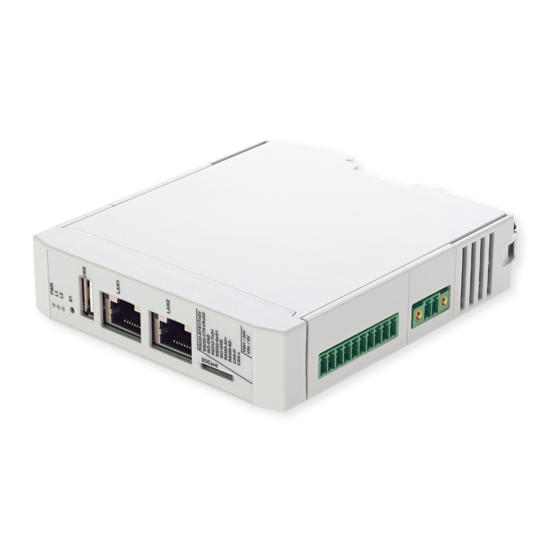
Manuals & Documentation – L-1028e.A2 i.MX 8 phyGATE-Tauri-L Kit Hardware and BSP Manual 3.2 Product Overview The phyGATE Tauri-L has several interfaces and controls/displays which are shown in the following figure. PB-03420-003.Ax PB-03420-001.Ax PB-03420-002.Ax Controls/Displays (25mm housing) (25mm housing) (50mm housing) 1. -
Page 13: Nameplate
(13.) SMA antenna connector (14.) internal miniPCIe slot (USB only) (15.) SIM card socket 3.3 Nameplate The nameplate of the phyGATE Tauri-L gateway is located on the side of the housing. Here you will find essential information about your device. Technical Data Warning All external circuits connected to the phyGATE Tauri-L terminals shall be SELV/PELV. - Page 14 Manuals & Documentation – L-1028e.A2 i.MX 8 phyGATE-Tauri-L Kit Hardware and BSP Manual PB-03420-002: max. 400 mA PB-03420-003: max. 2.5 A Power adapter type SELV/PELV Hardware Specification CPU type NXP i.MX 8M mini Quad-Core Cortex-A53 + Cortex-M4 max. 1,8 GHz (A53 core) / 400 MHz (M4 core) 2 GB eMMC 8 GB...
- Page 15 Manuals & Documentation – L-1028e.A2 i.MX 8 phyGATE-Tauri-L Kit Hardware and BSP Manual Software Specification Operating system Linux (Yocto) Security Features Device-Management / Cloud-Update concept Mechanical Data Housing type Phoenix ICS Housing material Polyamide Mounting type Top-hat rail mounting according to DIN EN 60715 IP protection class max.
- Page 16 Manuals & Documentation – L-1028e.A2 i.MX 8 phyGATE-Tauri-L Kit Hardware and BSP Manual Operating temperature -20 °C - +60 °C Humidity 10% - 95% non condensing Altitude max. 2000 m IP protection class control cabinet min. IP44 Product Information – 16...
-
Page 17: Package Contents/Accessories
1x LAN cable 2m 3.6 Certification The phyGATE Tauri-L has been approved for sale and use on the European market and meets the criteria for CE marking according to: • DIN EN 61000-6-2:2019-11 EMV Interference immunity for industrial areas •... -
Page 18: Technical Documentation And Support
Modification of the device, such as adjustments to the software or the use of additional devices in conjunction with the phyGATE Tauri-L Gateway, can influence the electrical properties of the device. In this case, the validity of the CE declaration of conformity is void. For a valid CE marking, a renewed approval by the operator must be carried out in this case. -
Page 19: Technical Product Information
Manuals & Documentation – L-1028e.A2 i.MX 8 phyGATE-Tauri-L Kit Hardware and BSP Manual 4 Technical Product Information Block Diagram Electrical Connection The phyGATE Tauri-L gateway has various interfaces for connection to the surrounding infrastructure. The following table lists the connections with the matching mating connectors. Technical Product Information – 19... - Page 20 Manuals & Documentation – L-1028e.A2 i.MX 8 phyGATE-Tauri-L Kit Hardware and BSP Manual phyGATE Tauri-L Interfaces Reference Connection Device Socket Mating Connector DC supply Phoenix MC 1,5/ 2-GF-3,81 Phoenix MC 1,5/ 2-STF-3,81 Phoenix FMC1.5/2-STF-3.81 Ethernet 1 RJ45 RJ45 Ethernet 0...
- Page 21 Manuals & Documentation – L-1028e.A2 i.MX 8 phyGATE-Tauri-L Kit Hardware and BSP Manual Boot-Switch Power-LED (green) D10 / D11 User-LEDs (red / yellow) (X23) Antenna connector SMA (female) SMA (male) Pinout of non-standard interfaces Reference Connection Function +24 VDC DC supply Device GND RS232_0_TX RS232_0_RX...
-
Page 22: Mechanical Connection
Cables with minimum size of AWG22 must be used for connection at the power supply terminal X28. Use copper conductor, only. All connected cables must have a temperature resistance of at least 90 °C. For the phyGATE Tauri-L variants with RS232 / RS485 / CAN, the function of the pins can be configured by the application software. - Page 23 Manuals & Documentation – L-1028e.A2 i.MX 8 phyGATE-Tauri-L Kit Hardware and BSP Manual To prevent malfunction or destruction of the device due to overheating, it is essential to ensure that the ventilation slots are not covered by surrounding components, cables, and other objects. The air must be able to circulate freely around the housing to dissipate heat.
-
Page 24: Getting Started With The Phygate Tauri-L Gateway
5 Getting Started with the phyGATE Tauri-L Gateway Introduction To easily get started with your phyGATE Tauri-L device, you'll find a description with the necessary tools and provision of the know-how to work with the Linux Board Support Package (BSP) for the phyCORE-i.MX 8M Mini below. -
Page 25: Prepare The Sd Card For Device Boot
To prepare the microSD card for the device boot, please follow the steps mentioned below. If you have a prepared SD card from the phyGATE Tauri-L Kit, this section can be skipped. If you are using your own SD Card, you'll have to download the prebuilt image file and burn it to the SD card first: Choose the right pre-built image from the phytec-ftp-server. -
Page 26: Booting The Board
5.4.2 Set Boot Switch The phyGATE Tauri-L provides a boot switch to choose the boot source of the device. You can choose either eMMC (DIP at position '1') or SD Card (DIP at position 'ON') as a boot source. ... -
Page 27: Powering The Board
Do not make any electrical changes with the interfaces and cables while the board is connected to power. This is to avoid damage to the device! Be aware that as soon as the phyGATE Tauri-L is supplied with power, the SD Card boot sequence will begin. Ensure that all cables are connected on the board! -
Page 28: Connecting The Os Via Ssh
Once the board is done booting, you can connect to the board via Ethernet and SSH. Therefore, you need to connect an RJ45 Ethernet cable between the phyGATE Tauri-L and your computer. Make sure that the IP configuration of your computer is configured as follows: •... -
Page 29: Setup Device Interfaces
> /sys/class/gpio/gpio89/value After that, you are able to configure the interface itself: target$ stty -F /dev/ttymxc3 115200 -brkint -icrnl -imaxbel -opost -onlcr -isig -icanon -iexten -echo -echoe -echok -echoctl -echoke raw Getting Started with the phyGATE Tauri-L Gateway – 29... -
Page 30: Connecting To Can
123#ab.cd.ef target$ candump can0 5.6.4 Connecting to USB The driver will detect USB-Devices automatically. To mount a USB-Flash for example, use the following commands: target$ mount /dev/disk/by-id/usb_san_disk_0:-part1 /mnt/ target$ cd /mnt Getting Started with the phyGATE Tauri-L Gateway – 30... -
Page 31: Building The Bsp
This section will guide you through the general build process of the i.MX 8M Mini BSP using the phyLinux script. If you want to use our software without phyLinux and the Repo tool managed environment instead, you can find all Git repositories on: git://git.phytec.de Used u-boot repository: git://git.phytec.de/u-boot-imx Our u-boot version is based on the u-boot-imx and adds only a few patches which will be sent upstream in future... -
Page 32: Finding The Right Software Platform
Finding the Right Software Platform The i.MX 8M Mini BSP is planned as a unified BSP, which means, in the future, it will support a set of different PHYTEC carrier boards (CB) with different Systems on Module (SOMs). However, this ALPHA BSP supports the PHYTEC machine:... -
Page 33: Bsp Images
• Kernel: Image • Kernel device tree file: oftree • Root filesystem: phytec-headless-image-phygate-tauri-l-imx8mm-1.tar.gz, phytec-headless-image- phygate-tauri-l-imx8mm-1.manifest • SD card image: phytec-headless-image-phygate-tauri-l-imx8mm-1.sdcard The default Linux image phytec-headless-image will start a Wayland Weston, even if there is no display connected. Building the BSP – 33... -
Page 34: System Booting
It contains all BSP files in correctly preformatted partitions and can be copied to the SD card easily using the single Linux command dd. The created file phytec-headless-image-phygate-tauri-l-imx8mm-2.sdcard is only a link to a file like phytec- headless-image-phygate-tauri-l-imx8mm-2-<BUILD-TIME>.rootfs.sdcard. Warning To create your bootable SD card with the dd command, you must have root privileges. -
Page 35: Four Individual Images (Imx-Boot, Kernel Image, Device Tree Image, Root Filesystem)
/dev/<your_device><number> • After having unmounted all devices with an appended number (<your_device><number>), you can create your bootable SD card with: host$ sudo dd of=/dev/<your_device> if=phytec-headless-image-phygate-tauri-l- imx8mm-2.sdcard bs=1MB conv=fsync status=progress • If you use the image file created by Bitbake instead: host$ sudo dd of=/dev/<your_device>... - Page 36 Manuals & Documentation – L-1028e.A2 i.MX 8 phyGATE-Tauri-L Kit Hardware and BSP Manual • Create a new Linux partition with partition id 83. Make sure you start this partition after the last sector of partition 1! By default, fdisk will try to use the first partition available on the disk, which in this example is 1000.
-
Page 37: Booting The Kernel From Network
Manuals & Documentation – L-1028e.A2 i.MX 8 phyGATE-Tauri-L Kit Hardware and BSP Manual • Then untar <IMAGENAME>-<MACHINE>.tar.gz rootfs image to it: host$ sudo mount /dev/sd<X>2 /media host$ sudo tar xfz <IMAGENAME>-<MACHINE>.tar.gz -C /media/ • Do not forget to properly unmount the SD card with: host$ sudo umount /media Booting the Kernel from Network Booting from the network means loading the kernel over TFTP and the root filesystem over NFS. - Page 38 Manuals & Documentation – L-1028e.A2 i.MX 8 phyGATE-Tauri-L Kit Hardware and BSP Manual host$ ifconfig eth1 You will receive: eth1 Link encap:Ethernet HWaddr 00:11:6b:98:e3:47 inet addr:192.168.3.10 Bcast:192.168.3.255 Mask:255.255.255.0 • Restart the services to pick up the configuration changes: host$ sudo service tftpd-hpa restart •...
-
Page 39: Updating Software
Take an uncompressed or compressed image on the host and send it with ssh through the network (then uncompress it, if necessary) to the eMMC of the target with a one-line command: target$ ssh <USER>@192.168.3.10 "dd if=<path_to_file>/phytec-headless-image-phygate- tauri-l-imx8mm-2.sdcard" | dd of=/dev/mmcblk2 8.1.2 Updating eMMC in Linux on Host It is also possible to update the eMMC from your Linux host. -
Page 40: Updating Emmc Via Sd Card
Resizing ext4 Root Filesystem (see page 53) 8.2.1 Updating eMMC via SD Card in Linux on Target You can also update the eMMC under Linux. You only need a complete image saved on the SD card (e.q. phytec- headless-image-phygate-tauri-l-imx8mm-2.sdcard). • Show your saved image files on the SD card: target$ ls phytec-headless-image-phygate-tauri-l-imx8mm-2.sdcard... -
Page 41: Rauc
Manuals & Documentation – L-1028e.A2 i.MX 8 phyGATE-Tauri-L Kit Hardware and BSP Manual RAUC The Robust Auto-Update Controller (RAUC) mechanism is a new addition to Yogurt. PHYTEC has written an online manual on how we have intergraded RAUC into our BSPs (L-1006e.A0 RAUC Update &... -
Page 42: Device Tree (Dt)
10.2 PHYTEC i.MX 8M Mini BSP Device Tree Concept The following sections explain some rules we have defined on how to set up device trees for our i.MX 8M Mini SoC- based boards. http://devicetree.org... -
Page 43: Dt Structure
Manuals & Documentation – L-1028e.A2 i.MX 8 phyGATE-Tauri-L Kit Hardware and BSP Manual 10.2.1 DT Structure The module includes file Modul .dtsi which contains all devices which are mounted on the module, such as PMIC and RAM. Devices which come from the i.MX 8M Mini SoC but are just routed down to the carrier board are not part of the Module .dtsi. -
Page 44: Accessing Peripherals
Manuals & Documentation – L-1028e.A2 i.MX 8 phyGATE-Tauri-L Kit Hardware and BSP Manual Accessing Peripherals To find out which boards and modules are supported by the release of PHYTEC’s i.MX8 BSP described herein, visit our web page at http://www.phytec.de/produkte/software/yocto/phytec-unified-yocto-bsp-releases/ and click the corresponding BSP release. -
Page 45: Serial Ttys
11.2 Serial TTYs The i.MX 8M Mini SoC provides up to 4 so-called UART units. PHYTEC boards support different numbers of these UART units. To use UART1 in the Alpha Kit, the S1 POS3 has to be set to ON. -
Page 46: Rs-485
Manuals & Documentation – L-1028e.A2 i.MX 8 phyGATE-Tauri-L Kit Hardware and BSP Manual [...] &iomuxc { imx8mm-phyGATE-Tauri { [...] pinctrl_uart4: uart4grp { fsl,pins = < MX8MM_IOMUXC_UART4_RXD_UART4_DCE_RX 0x49 MX8MM_IOMUXC_UART4_TXD_UART4_DCE_TX 0x49 MX8MM_IOMUXC_SAI5_MCLK_GPIO3_IO25 0x49 >;... - Page 47 Manuals & Documentation – L-1028e.A2 i.MX 8 phyGATE-Tauri-L Kit Hardware and BSP Manual The DT Ethernet setup might be split into two files depending on your hardware configuration: the module DT, and the board-specific DT. Module DT, arch/arm64/boot/dts/freescale/phytec-imx8mm-phycore-som.dtsi: […] #include <dt-bindings/net/ti-dp83867.h>...
-
Page 48: Sd / Mmc Card
If it does not contain one, the whole device can be used as a file system (”floppy” like handling). In this case, /dev/mmcblk1 must be used for formatting and mounting. The cards are always mounted as being writable. DT configuration for the MMC (SD card slot) interface in arch/arm64/boot/dts/freescale/phytec-imx8mm-phyGATE- Tauri.dtsi: […] ... - Page 49 Manuals & Documentation – L-1028e.A2 i.MX 8 phyGATE-Tauri-L Kit Hardware and BSP Manual pinctrl-1 = <&pinctrl_usdhc2_100mhz>, <&pinctrl_usdhc2_gpio>; pinctrl-2 = <&pinctrl_usdhc2_200mhz>, <&pinctrl_usdhc2_gpio>; cd-gpios = <&gpio2 GPIO_ACTIVE_LOW>; bus-width = <4>; status = "okay"; no-1-8-v; […] &iomuxc { imx8mm-phyGATE-Tauri { ...
- Page 50 Manuals & Documentation – L-1028e.A2 i.MX 8 phyGATE-Tauri-L Kit Hardware and BSP Manual >; […] DT configuration for the eMMC interface in arch/arm64/boot/dts/freescale/phytec-imx8mm-phycore-som.dtsi: […] &usdhc3 { vqmmc-supply = <®_sw6>; pinctrl-names = "default", "state_100mhz", "state_200mhz"; pinctrl-0 = <&pinctrl_usdhc3>; pinctrl-1 = <&pinctrl_usdhc3_100mhz>;...
-
Page 51: Emmc Devices
11.6 eMMC Devices PHYTEC modules like phyCORE-i.MX 8M Mini are populated with an eMMC memory chip as main storage. eMMC devices contain raw MLC memory cells combined with a memory controller that handles ECC and wear leveling. They are connected via an MMC/SD interface to the i.MX 8M Mini and are represented as block devices in the Linux kernel like SD cards, flash drives, or hard disks. -
Page 52: Enabling Background Operations (Bkops)
Manuals & Documentation – L-1028e.A2 i.MX 8 phyGATE-Tauri-L Kit Hardware and BSP Manual • In the Linux user space, you can query the registers with: target$ mmc extcsd read /dev/mmcblk2 You will see: ============================================= Extended CSD rev (MMC 5.1) ============================================= Card Supported Command sets [S_CMD_SET: 0x01] [...] 11.6.2 Enabling Background Operations (BKOPS) In contrast to raw NAND Flash, an eMMC device contains a Flash Transfer Layer (FTL) that handles the wear leveling,... -
Page 53: Reliable Write
Manuals & Documentation – L-1028e.A2 i.MX 8 phyGATE-Tauri-L Kit Hardware and BSP Manual Where value 0x00 means BKOPS_EN is disabled and device write performance suffers. Where value 0x01 means BKOPS_EN is enabled and the host will issue background operations from time to time. • To set the BKOPS_EN bit, execute: target$ mmc bkops enable /dev/mmcblk0 •... - Page 54 Manuals & Documentation – L-1028e.A2 i.MX 8 phyGATE-Tauri-L Kit Hardware and BSP Manual target$ fdisk -l /dev/mmcblk2 • The output looks like: Disk /dev/mmcblk2: 15913189376 bytes, 31080448 sectors 485632 cylinders, heads, sectors/track Units: sectors of bytes Device Boot StartCHS EndCHS StartLBA EndLBA Sectors Size Id Type /dev/mmcblk2p1 * 64,0,1 762,2,28 8192 97627 89436 43.6M c Win)
-
Page 55: Erasing The Device
Manuals & Documentation – L-1028e.A2 i.MX 8 phyGATE-Tauri-L Kit Hardware and BSP Manual Last sector or +size{,K,M,G,T} (98304-31080447, default 31080447): Using default value 31080447 Command (m help): p Disk /dev/mmcblk2: 15913189376 bytes, 31080448 sectors 485632 cylinders, heads, sectors/track Units: sectors of bytes ... -
Page 56: Gpios
It lists all MTD devices and the corresponding partition names. The flash node is defined inside the SPI master node in the module DTS. The SPI node contains all devices connected to this SPI bus which is in this case only the SPI NOR Flash. Definition of the SPI master node in imx6qdl-phytec-phycore-som.dtsi : &flexspi { pinctrl-names = "default";... - Page 57 Manuals & Documentation – L-1028e.A2 i.MX 8 phyGATE-Tauri-L Kit Hardware and BSP Manual The GPIOs are identified as GPIO<X>_<Y> (e.g. GPIO5_07). <X> identifies the GPIO bank and counts from 1 to 5, while <Y> stands for the GPIO within the bank. <Y> is being counted from 0 to 31 (32 GPIOs on each bank). By contrast, the Linux kernel uses a single integer to enumerate all available GPIOs in the system.
-
Page 58: Leds
Some of the user IOs are used for special functions. Before using a user IO, refer to the schematic or the hardware manual of your board to ensure that it is not already in use. Pinmuxing of some GPIO pins in the device tree phytec-imx8mm-phyGATE-Tauri.dtsi: pinctrl_leds: leds1grp { fsl,pins = <... - Page 59 Manuals & Documentation – L-1028e.A2 i.MX 8 phyGATE-Tauri-L Kit Hardware and BSP Manual target$ echo > /sys/class/leds/led-red/brightness • To toggle OFF: target$ echo > /sys/class/leds/led-red/brightness • User I/O configuration in device tree file arch/arm64/boot/dts/freescale/phytec-imx8mm-phyGATE-Tauri.dtsi: leds { compatible = "gpio-leds"; pinctrl-names = "default"; pinctrl-0 = <&pinctrl_leds>; led-red { label = "red-emmc";...
-
Page 60: I2C Bus
11.10 C Bus The i.MX 8M Mini contains three Multimaster fast-mode I²C modules called I2C1, I2C2, I2C3, and I2C4. PHYTEC boards provide plenty of different I²C devices connected to the I²C modules of the i.MX 8M Mini. This chapter will describe the basic device usage and its DT representation of some of the I²C devices integrated on our phyGATE-... -
Page 61: Eeprom
To fill the whole EEPROM with zeros, use: target$ dd if=/dev/zero of=/sys/class/i2c-dev/i2c-0/device/0-0051/eeprom bs=4096 count=1 This operation takes some time because the EEPROM is relatively slow. DT representation, e.g. in phyCORE-i.MX 8M Mini file phytec-imx8mm-phycore-som.dtsi: &i2c1 { clock-frequency = <400000>; pinctrl-names = "default"; pinctrl-0 = <&pinctrl_i2c1>;... -
Page 62: Can Fd
Manuals & Documentation – L-1028e.A2 i.MX 8 phyGATE-Tauri-L Kit Hardware and BSP Manual 11.12 CAN FD The phyBOARD-Polis is populated with an mcp2517fd SPI to CAN FD chip. The chip is supported with the Linux standard CAN framework which builds upon then the Linux network layer. Using this framework, the CAN interfaces behave like an ordinary Linux network device, with some additional features special to CAN. - Page 63 Manuals & Documentation – L-1028e.A2 i.MX 8 phyGATE-Tauri-L Kit Hardware and BSP Manual Field Description can0 Interface Name NOARP CAN cannot use ARP protocol Maximum Transfer Unit RX packets Number of Received Packets TX packets Number of Transmitted Packets RX bytes Number of Received Bytes TX bytes Number of Transmitted Bytes...
- Page 64 Manuals & Documentation – L-1028e.A2 i.MX 8 phyGATE-Tauri-L Kit Hardware and BSP Manual target$ ip link set can0 txqueuelen up type can bitrate 500000 sample-point 0.75 dbitrate 4000000 dsample-point fd on You can send messages with cansend or receive messages with candump: target$ cansend can0 123#45.67 target$ candump can0 To generate random CAN traffic for testing purpose, use cangen:...
-
Page 65: Rtc
>; [...] 11.13 RTCs can be accessed via /dev/rtc*. Because PHYTEC boards have often more than one RTC, there might be more than one RTC device file. • To find the name of the RTC device, you can read its sysfs entry with: target$ cat /sys/class/rtc/rtc*/name •... -
Page 66: Usb Host Controller
Due to udev, all mass storage devices connected get unique IDs and can be found in /dev/disks/by-id. These IDs can be used in /etc/fstab to mount the different USB memory devices in different ways. User USB2 (host) configuration is in the kernel device tree phytec-imx8mm-phyGATE-Tauri.dtsi: […] ... -
Page 67: Usb Otg
USB OTG Most PHYTEC boards provide a USB OTG interface. USB OTG ports automatically act as a USB device or USB host. The mode depends on the USB hardware attached to the USB OTG port. If, for example, a USB mass storage device is attached to the USB OTG port, the device will show up as /dev/sda. - Page 68 If your system has more than one USB Device or OTG port, you can pass the right one to the USB Device Controller (UDC). • To stop the USB gadget and unbind the used functions execute: target$ echo "" > /sys/kernel/config/usb_gadget/g1/UDC User USB OTG configuration in the kernel device tree phytec-imx8mm-phyGATE-Tauri.dtsi: [...] reg_usb_otg1_vbus: regulator-usb-otg1-vbus { pinctrl-names = "default"; pinctrl-0 = <&pinctrl_usbotg1pwrgrp>;...
-
Page 69: Tpm
The TPM is connected over the SPI interface. Currently, we support a basic driver implementation. Bootlog output: tpm_tis_spi spi1.0: TPM (device-id 0x1B, rev-id 16) TPM configuration in the kernel device tree phytec-imx8mm-phyGATE-Tauri.dtsi: /* TPM */ &ecspi2 { #address-cells = <1>;... -
Page 70: Pcie
Manuals & Documentation – L-1028e.A2 i.MX 8 phyGATE-Tauri-L Kit Hardware and BSP Manual interrupt-parent = <&gpio2>; interrupts = <11 IRQ_TYPE_LEVEL_LOW>; #endif 11.17 PCIe The phyCORE-i.MX 8M Mini has one Mini-PCIe slot. In general, PCIe autodetects new devices on the bus. After connecting the device and booting up the system, you can use the command lspci to see all PCIe devices recognized. -
Page 71: Cpu Core Management
Manuals & Documentation – L-1028e.A2 i.MX 8 phyGATE-Tauri-L Kit Hardware and BSP Manual • In order to activate the driver, use: host$ bitbake virtual/kernel -c menuconfig For some devices like the WLAN card, additional binary firmware blobs are needed. These firmware blobs have to be placed in /lib/firmware/ before the device can be used. -
Page 72: Thermal Management
Manuals & Documentation – L-1028e.A2 i.MX 8 phyGATE-Tauri-L Kit Hardware and BSP Manual [...] Here the system has four processor cores. By default, all available cores in the system are enabled to get maximum performance. • To switch off a single-core, execute: target$ echo >... - Page 73 Manuals & Documentation – L-1028e.A2 i.MX 8 phyGATE-Tauri-L Kit Hardware and BSP Manual These trip points are used by the kernel thermal management to trigger events and change the cooling behavior. The following thermal policies (also named thermal governors) are available in the kernel: Step Wise, Fair Share, Bang Bang, and Userspace. The default policy used in the BSP is step_wise. If the value of the SoC temperature in the sysfs file temp is above trip_point_0 (greater than 85 °C), the CPU frequency is set to the lowest CPU frequency.
-
Page 74: Revision History
Manuals & Documentation – L-1028e.A2 i.MX 8 phyGATE-Tauri-L Kit Hardware and BSP Manual 12 Revision History Date Version # Changes in this manual 17.06.2021 L-1028e.A0 Preliminary Version 28.09.2021 L-1028e.A1 Updated Power Information 15.03.2022 L-1028e.A2 Updated housing information Revision History – 74...
Need help?
Do you have a question about the phyGATE Tauri-L and is the answer not in the manual?
Questions and answers