
Related Manuals for Phytec L-863e.A2 phyCORE-i.MX 8M


Summary of Contents for Phytec L-863e.A2 phyCORE-i.MX 8M
- Page 1 L-863e.A2 phyCORE-i.MX 8M / phyBOARD-Polaris (1497.3 / 1501.2) Hardware Manual A product of PHYTEC Technology Holding Company...
- Page 2 L-863e.A2 phyCORE-i.MX 8M / phyBOARD-Polaris (1497.3 / 1501.2) Hardware Manual © PHYTEC Messtecknik GmbH...
-
Page 3: Information On This Manual
The schematics shown in this hardware manual are believed to be correct. However, correctness can not be guaranteed. The schematics have been pulled from PHYTEC's designs that have been built, tested, and is known to work. The schematics have been re-formatted to fit better in this hardware manual. -
Page 4: Ordering Information
Production-ready Board Support Packages (BSPs) and Design Services for our hardware will further reduce development time and risk and allows for increased focus on product expertise. Take advantage of PHYTEC products to shorten time-to-market, reduce development costs, and avoid substantial design issues and risks. With this new innovative, full-system solution, new ideas can be brought to market in the most timely and cost-efficient manner. - Page 5 Populated on the SOM / SBC With the purchase of a PHYTEC SOM / SBC, you will, in addition to our hardware and software possibilities, receive free obsolescence maintenance service for the hardware we provide. Our PCM (Product Change Management) team of developers is continuously processing all incoming PCNs (Product Change Notifications) from vendors and distributors concerning parts that are used in our products.
- Page 6 2.5 PHYTEC Documentation PHYTEC will provide a variety of hardware and software documentation for all of our products. This includes any or all of the following: •...
- Page 7 L-863e.A2 phyCORE-i.MX 8M / phyBOARD-Polaris (1497.3 / 1501.2) Hardware Manual On top of these standard manuals and guides, PHYTEC will also provide Product Change Notifications, Application Notes, and Technical Notes. These will be done on a case-by-case basis. Most of the documentation can be found on the applicable download page of our products.
- Page 8 L-863e.A2 phyCORE-i.MX 8M / phyBOARD-Polaris (1497.3 / 1501.2) Hardware Manual 3 Conversions, Abbreviations, and Acronyms ® This hardware manual describes the PCL-066 System on Module, referred to as phyCORE -i.MX 8M, and the ® PB-02419-xxxI.Ax, referred to as phyBOARD -Polaris. This manual also specifies the phyCORE-i.MX 8M and phyBOARD-Polaris' design and function.
- Page 9 L-863e.A2 phyCORE-i.MX 8M / phyBOARD-Polaris (1497.3 / 1501.2) Hardware Manual Signal Type Description Abbreviation Input Digital input Output Digital output IO Bidirectional input/output OC-Bidir Open collector input/output with pull up OC-BI OC-Output Open collector output without pull-up, requires an external pull up OD-Bidir PU ...
-
Page 10: Abbreviations And Acronyms
L-863e.A2 phyCORE-i.MX 8M / phyBOARD-Polaris (1497.3 / 1501.2) Hardware Manual 3.3 Abbreviations and Acronyms Many acronyms and abbreviations are used throughout this manual. Use the following table to navigate unfamiliar terms used in this document. TABLE 2: Abbreviations and Acronyms Used in this Manual... - Page 11 L-863e.A2 phyCORE-i.MX 8M / phyBOARD-Polaris (1497.3 / 1501.2) Hardware Manual Abbreviation Definition Single Board Computer Surface mount technology ® System on Module; used in reference to the PCL-066 /phyCORE -i.MX 8M module User button Sx (e.g. S1, S2, etc.) used in reference to the available user buttons,...
- Page 12 L-863e.A2 phyCORE-i.MX 8M / phyBOARD-Polaris (1497.3 / 1501.2) Hardware Manual 4 phyCORE-i.MX 8M Introduction The phyCORE‑i.MX 8M belongs to PHYTEC’s phyCORE System on Module family. The phyCORE SOMs represent the continuous development of PHYTEC System on Module technology. Like its mini-, micro-, and nanoMODUL...
- Page 13 Grades) 1. The maximum memory size listed as of the printing of this manual. Please contact PHYTEC for more information about additional or new module configurations available. 2. Please refer to the order options described in the Preface or contact PHYTEC for more information about additional module configurations.
- Page 14 L-863e.A2 phyCORE-i.MX 8M / phyBOARD-Polaris (1497.3 / 1501.2) Hardware Manual 4.3 phyCORE-i.MX 8M Component Placement FIGURE 2: phyCORE-i.MX 8M Component Placement (Top View) © PHYTEC Messtecknik GmbH...
- Page 15 L-863e.A2 phyCORE-i.MX 8M / phyBOARD-Polaris (1497.3 / 1501.2) Hardware Manual FIGURE 3: phyCORE-i.MX 8M Component Placement (Bottom View) 4.4 phyCORE-i.MX 8M Minimum Operating Requirements Warning We recommend connecting all available +3.3 V input pins to the power supply system on a custom carrier board housing the phyCORE-i.MX 8M and, at minimum, the matching number of GND balls neighboring the...
-
Page 16: Pin Description
L-863e.A2 phyCORE-i.MX 8M / phyBOARD-Polaris (1497.3 / 1501.2) Hardware Manual 5 Pin Description Warning Module connections must not exceed their expressed maximum voltage or current. Maximum signal input values are indicated in the corresponding controller manuals/datasheets. As damage from improper... - Page 17 L-863e.A2 phyCORE-i.MX 8M / phyBOARD-Polaris (1497.3 / 1501.2) Hardware Manual Tips • Most of the controller pins have multiple multiplexed functions. As most of these pins are connected directly to the phyCORE-Connector, the alternative functions are available by using the i.MX 8M's pin muxing options.
- Page 18 L-863e.A2 phyCORE-i.MX 8M / phyBOARD-Polaris (1497.3 / 1501.2) Hardware Manual 6 Jumpers For configuration purposes, the phyCORE‑i.MX 8M has several solder jumpers, some of which have been installed prior to delivery. Typical Jumper Pad Numbering Scheme illustrates the numbering scheme for the various solder jumper pads. Jumper Locations (Top View)
- Page 19 L-863e.A2 phyCORE-i.MX 8M / phyBOARD-Polaris (1497.3 / 1501.2) Hardware Manual FIGURE 5: Jumper Locations (Top View) FIGURE 6: Jumper Locations (Bottom View) © PHYTEC Messtecknik GmbH...
- Page 20 L-863e.A2 phyCORE-i.MX 8M / phyBOARD-Polaris (1497.3 / 1501.2) Hardware Manual Pay special attention to the “TYPE” column to ensure you are using the correct type of jumper (0 Ohms, 10k Ohms, etc…). The jumpers are 0201 packages with a 1/8 W or better power rating.
- Page 21 L-863e.A2 phyCORE-i.MX 8M / phyBOARD-Polaris (1497.3 / 1501.2) Hardware Manual Jumper Position Description Type Section GPIO1_IO09 available on BGA Ball (Default if WIFI/ BT is not mounted) WIFI_WLAN_RF_KIL L_L available on BGA Ball RMGII IO Voltage set to 1.8V. 0201...
- Page 22 L-863e.A2 phyCORE-i.MX 8M / phyBOARD-Polaris (1497.3 / 1501.2) Hardware Manual Jumper Position Description Type Section GPIO1_IO14 available on BGA Ball (Default if WIFI/ BT is not mounted) PMIC_nSDWN available on BGA Ball internal use only 0201 © PHYTEC Messtecknik GmbH...
- Page 23 Connector X1. Warning As a general design rule, PHYTEC recommends connecting all GND pins neighboring signals which are being used in the application circuitry. For maximum EMI performance, all GND pins should be connected to a solid ground plane.
- Page 24 L-863e.A2 phyCORE-i.MX 8M / phyBOARD-Polaris (1497.3 / 1501.2) Hardware Manual • VDD_IN_3V3 3.3 V main supply voltage • USB0_VBUS USB0 bus voltage must be supplied with 5 V if USB0 is used (does not exceed 5.25V) • USB1_VBUS USB1 bus voltage must be supplied with 5 V if USB1 is used (does not exceed 5.25V) •...
- Page 25 L-863e.A2 phyCORE-i.MX 8M / phyBOARD-Polaris (1497.3 / 1501.2) Hardware Manual 8 Reset The X_nRESET_IN signal (Pin A62) on the phyCORE-Connector is designated as the reset input. Holding this pin low triggers a hard reset of the module. The external reset signal has a 10ms debouncing circuit. X_POR_B Signal (Pin A61) can be used to prevent bootup of the i.MX8M.
-
Page 26: System Boot Configuration
L-863e.A2 phyCORE-i.MX 8M / phyBOARD-Polaris (1497.3 / 1501.2) Hardware Manual 9 System Boot Configuration Most features of the i.MX 8 microcontroller are configured and/or programmed during the initialization routine. Other features, which impact program execution, must be configured prior to initialization via pin termination. - Page 27 L-863e.A2 phyCORE-i.MX 8M / phyBOARD-Polaris (1497.3 / 1501.2) Hardware Manual pins. On the phyCORE‑i.MX 8M, the GPIOs have 10 kΩ pull-up and pull-down resistors preinstalled to configure eFUSEs BOOT_CFGx[7:0] in accordance with the module features. The specific boot configuration settings, which are set by the onboard configuration resistors, can be changed by modifying the resistors on the module or by connecting a configuration resistor (e.g.
- Page 28 L-863e.A2 phyCORE-i.MX 8M / phyBOARD-Polaris (1497.3 / 1501.2) Hardware Manual Boot Addres BOOT_ BOOT_ BOOT_ BOOT_ BOOT_ BOOT_ BOOT_ BOOT_ Source CFG[15 CFG[14 CFG[13 CFG[12 CFG[11 CFG[10 CFG[9] CFG[8] QSPI SDR SMP: 100 - QSPI Instanc 000: Default 001 - 111...
- Page 29 L-863e.A2 phyCORE-i.MX 8M / phyBOARD-Polaris (1497.3 / 1501.2) Hardware Manual Boot Addres BOOT_ BOOT_ BOOT_ BOOT_ BOOT_ BOOT_ BOOT_ BOOT_ Source CFG[15 CFG[14 CFG[13 CFG[12 CFG[11 CFG[10 CFG[9] CFG[8] Speed 000 - Normal/SDR12 001 - High/SDR25 SD/eSD 010 - SDR50...
- Page 30 L-863e.A2 phyCORE-i.MX 8M / phyBOARD-Polaris (1497.3 / 1501.2) Hardware Manual Boot Addres BOOT_ BOOT_ BOOT_ BOOT_ BOOT_ BOOT_ BOOT_ BOOT_ Source CFG[15 CFG[14 CFG[13 CFG[12 CFG[11 CFG[10 CFG[9] CFG[8] HSPHS: HSDLY: FSPHS: FSDLY: Half- Half- Full Full Speed Speed Speed...
-
Page 31: System Memory
The three lower address bits are fixed to zero which means that the EEPROM can be accessed at I C address 0x52. The EEPROM has a second address on 0x5A, which is called Identification Page, and is reserved for internal PHYTEC uses only. - Page 32 L-863e.A2 phyCORE-i.MX 8M / phyBOARD-Polaris (1497.3 / 1501.2) Hardware Manual 10.4 QSPI NOR Flash (U40) The QSPI NOR Flash memory of the phyCORE-i.MX 8M at U40 can be used to store configuration data or any other general-purpose data. It can also be used as a boot device and recovery boot device. The device is accessed through QSPIA SS0 on the i.MX 8.
-
Page 33: Serial Interfaces
L-863e.A2 phyCORE-i.MX 8M / phyBOARD-Polaris (1497.3 / 1501.2) Hardware Manual 11 Serial Interfaces The phyCORE‑i.MX 8M provides numerous dedicated serial interfaces, some of which are equipped with a transceiver to enable direct connection to external devices: 1x 4-bit SDIO interface 4x high-speed UARTs 2x USB 3.0/2.0 OTG interfaces... - Page 34 L-863e.A2 phyCORE-i.MX 8M / phyBOARD-Polaris (1497.3 / 1501.2) Hardware Manual SOM Signal Name SOM Voltage Signal Level Signal Type Description Connector Domain Pin / phyBOARD- Polaris Carrier Board Connector Pin X_SD2_CMD_EXT 3.3V/1.8V SD2 Command X_SD2_DATA3_EXT 3.3V/1.8V SD2 DATA3 X_SD2_DATA2_EXT 3.3V/1.8V SD2 DATA2 ...
-
Page 35: Usb Interfaces
L-863e.A2 phyCORE-i.MX 8M / phyBOARD-Polaris (1497.3 / 1501.2) Hardware Manual SOM Connector SOM Signal SOM Voltage Signal Level Signal Type Description Pin / Name Domain phyBOARD- Polaris Carrier Board Connector Pin X_UART2_RXD NVCC_UART 3.3 V UART2 Receive Data X_UART2_TXD NVCC_UART 3.3 V... - Page 36 L-863e.A2 phyCORE-i.MX 8M / phyBOARD-Polaris (1497.3 / 1501.2) Hardware Manual TABLE 10: USB 1 Signal Locations SOM Connector SOM Signal SOM Voltage Signal Level Signal Type Description Pin / Name Domain phyBOARD- Polaris Carrier Board Connector Pin X_USB1_DP USB_P0_VDD3 USB 1 Data+...
-
Page 37: Ethernet Interface
L-863e.A2 phyCORE-i.MX 8M / phyBOARD-Polaris (1497.3 / 1501.2) Hardware Manual SOM Connector SOM Signal SOM Voltage Signal Level Signal Type Description Pin / Name Domain phyBOARD- Polaris Carrier Board Connector Pin X_USB2_TX_N USB_P1_VPH USB 2 Transmit Data- X_USB2_RX_P USB_P1_VPH USB 2 Receive... - Page 38 L-863e.A2 phyCORE-i.MX 8M / phyBOARD-Polaris (1497.3 / 1501.2) Hardware Manual TABLE 12: Ethernet Signal Locations SOM Signal Name SOM Voltage Signal Level Signal Type Description Connector Domain Pin / phyBOARD- Polaris Carrier Board Connector Pin X_ETH0_LED2_ACT Activity X_ETH0_LED0_LINK Link X_ETH0_A+ Data A+...
- Page 39 MAC address. In order to guarantee that the MAC address is unique, all addresses are managed in a central location. PHYTEC has acquired a pool of MAC addresses. The MAC address of the phyCORE‑i.MX 8M is located on the bar code sticker attached to the module. This number is a 12-digit HEX value.
- Page 40 L-863e.A2 phyCORE-i.MX 8M / phyBOARD-Polaris (1497.3 / 1501.2) Hardware Manual SOM Signal Name SOM Voltage Signal Level Signal Type Description Connector Domain Pin / phyBOARD- Polaris Carrier Board Connector X_ENET0_RGMII_RX_CTL 1.8 V (*3.3 V) Receive Control X_ENET0_RGMII_RXC 1.8 V (*3.3 V)
- Page 41 L-863e.A2 phyCORE-i.MX 8M / phyBOARD-Polaris (1497.3 / 1501.2) Hardware Manual TABLE 14: SPI Interface Signal Locations SOM Connector SOM Signal SOM Voltage Signal Level Signal Type Description Pin / Name Domain phyBOARD- Polaris Carrier Board Connector Pin X_ECSPI1_MOSI NVCC_ECSPI 3.3 V...
-
Page 42: Audio Interface
L-863e.A2 phyCORE-i.MX 8M / phyBOARD-Polaris (1497.3 / 1501.2) Hardware Manual TABLE 15: I2C Interface Signal Locations SOM Connector SOM Signal SOM Voltage Signal Type Signal Level Description Pin / Name Domain phyBOARD- Polaris Carrier Board Connector Pin X_I2C2_SCL 3.3 V I2C2 Clock X_I2C2_SDA 3.3 V... - Page 43 L-863e.A2 phyCORE-i.MX 8M / phyBOARD-Polaris (1497.3 / 1501.2) Hardware Manual 11.7.1 I S Audio Interface (SAI) The phyCORE-i.MX 8M features a Synchronous Audio Interface that supports full-duplex serial interfaces with frame synchronization such as I2S, AC97, and TDM. The interface is divided into four sub-interfaces SAI1, SAI2, SAI3, and SAI5.
- Page 44 L-863e.A2 phyCORE-i.MX 8M / phyBOARD-Polaris (1497.3 / 1501.2) Hardware Manual SOM Connector SOM Signal SOM Voltage Signal level Signal Type Description Pin / Name Domain phyBOARD- Polaris Carrier Board Connector Pin X_SAI1_RXD7/ NVCC_SAI1 3.3 V SAI1 RXD7 BOOT_CFG7 X_SAI1_RXD6/ NVCC_SAI1 3.3 V...
- Page 45 L-863e.A2 phyCORE-i.MX 8M / phyBOARD-Polaris (1497.3 / 1501.2) Hardware Manual SOM Connector SOM Signal SOM Voltage Signal Level Signal Type Description Pin / Name Domain phyBOARD- Polaris Carrier Board Connector Pin X_SAI2_RXD0 NVCC_SAI2 3.3 V SAI2 RXD0 X_SAI2_TXD0 NVCC_SAI2 3.3 V...
- Page 46 Gbit/s operations. Furthermore, the interfaces are fully backward compatible with the 2.5 Gbit/s Gen. 1.1 specifications. Additional control signals which might be required (e.g. “present” and “wake”) can be implemented with GPIOs. Please refer to the schematic of a suitable PHYTEC carrier board (e.g. phyBOARD‑Polaris) for a circuit example.
- Page 47 L-863e.A2 phyCORE-i.MX 8M / phyBOARD-Polaris (1497.3 / 1501.2) Hardware Manual TABLE 22: PCIe Interface Signal Locations SOM Connector SOM Signal SOM Voltage Signal Level Signal Type Description Pin / Name Domain phyBOARD- Polaris Carrier Board Connector Pin A107 X_PCIE1_TXN_N PCIE0_VPH PCIe1 TXN-...
-
Page 48: General Purpose I/Os
L-863e.A2 phyCORE-i.MX 8M / phyBOARD-Polaris (1497.3 / 1501.2) Hardware Manual 12 General Purpose I/Os All pins not used by any of the other interfaces specifically described in this manual and can be used as GPIO without harming other features of the phyCORE‑i.MX 8M. These pins are shown below:... - Page 49 L-863e.A2 phyCORE-i.MX 8M / phyBOARD-Polaris (1497.3 / 1501.2) Hardware Manual SOM Connector SOM Signal SOM Voltage Signal Level Signal Type Description Pin / Name Domain phyBOARD- Polaris Carrier Board Connector Pin X_GPIO1_IO11 NVCC_GPI01 3.3 V GPIO1_11 (only available if WIFI is not mounted...
-
Page 50: Debug Interface
L-863e.A2 phyCORE-i.MX 8M / phyBOARD-Polaris (1497.3 / 1501.2) Hardware Manual 13 Debug Interface The phyCORE‑i.MX 8M is equipped with a JTAG interface to download program code into the external flash, internal controller RAM, or any debugging programs being executed. The locations of the JTAG pins on the phyCORE-... -
Page 51: Display Interfaces
L-863e.A2 phyCORE-i.MX 8M / phyBOARD-Polaris (1497.3 / 1501.2) Hardware Manual 14 Display Interfaces 14.1 High Definition Multimedia Interface (HDMI) The High Definition Multimedia Interface (HDMI) of the phyCORE-i.MX 8M is compliant with HDMI 2.0a as well as DP 1.3 and eDP 1.4. It supports a maximum pixel clock of up to 596 MHz for up to 2160p at 60 Hz UHDTV display resolutions and a graphic display resolution works up to 4096x2160 (QFHD). - Page 52 L-863e.A2 phyCORE-i.MX 8M / phyBOARD-Polaris (1497.3 / 1501.2) Hardware Manual SOM Signal Name SOM Voltage Signal Level Signal Type Description Connector Domain Pin / phyBOARD- Polaris Carrier Board Connector Pin X_HDMI_DDC_SDA HDMI_AVDDIO Display Data Channel SDA X_HDMI_HPD HDMI_AVDDIO Hot Plug Detect...
-
Page 53: Camera Connections
L-863e.A2 phyCORE-i.MX 8M / phyBOARD-Polaris (1497.3 / 1501.2) Hardware Manual 15 Camera Connections The phyCORE-i.MX 8M offers 2 MIPI-CSI interfaces to connect digital cameras with a resolution of up to 4k at 30fps. The two MIPI/CSI‑2 camera interfaces of the i.MX 8M extend to the phyCORE‑Connector X31 with 4 data lanes and one clock lane. - Page 54 L-863e.A2 phyCORE-i.MX 8M / phyBOARD-Polaris (1497.3 / 1501.2) Hardware Manual SOM Signal Name SOM Voltage Signal Level Signal Type Description Connector Domain Pin / phyBOARD- Polaris Carrier Board Connector Pin A101 X_MIPI_CSI1_CLK_P CSI_P1_VDDHA CSI1 Clock+ A102 X_MIPI_CSI1_CLK_N CSI_P1_VDDHA CSI1 Clock- A103...
- Page 55 L-863e.A2 phyCORE-i.MX 8M / phyBOARD-Polaris (1497.3 / 1501.2) Hardware Manual SOM Signal Name SOM Voltage Signal Level Signal Type Description Connector Domain Pin / phyBOARD- Polaris Carrier Board Connector Pin A124 X_MIPI_DSI_D2_N DSI_VDDHA DSI DATA2- A131 X_MIPI_DSI_D3_P DSI_VDDHA DSI DATA3+...
- Page 56 16 WIFI/Bluetooth 16.1 WIFI The i.MX8M is the first SOM in the PHYTEC phyCORE family with onboard Wifi/Bluetooth support. This feature is made possible with a Sterling-LWB module soldered onto the SOM. This module supports Wifi according to IEEE 802.11 b/g/n and Bluetooth v4.2 BR /DR/LE.
- Page 57 L-863e.A2 phyCORE-i.MX 8M / phyBOARD-Polaris (1497.3 / 1501.2) Hardware Manual TABLE 30: J6 Settings Options BT_EN X_GPIO1_IO11 GPIO1_IO11 X_BT_EN TABLE 31: J7 Settings Options WIFI_HCI_UART/WAKEHOST_L X_GPIO1_IO08 GPIO1_IO08 X_WIFI_HCI_UART/WAKEHOST_L TABLE 32: J8 Settings Options WIFI_WLAN_RF_KILL_L X_GPIO1_IO09 GPIO1_IO09 X_WIFI_WLAN_RF_KILL_L © PHYTEC Messtecknik GmbH...
- Page 58 The i.MX 8M has an onboard, externally mounted RTC. The RV-3028 is the newest generation of RTC from Micro Crystal with an extremely low backup current of typically 40nA at 25 degrees. PHYTEC uses the most optimal implementation in each phyCORE design to give the most optimal usage for all customers.
- Page 59 L-863e.A2 phyCORE-i.MX 8M / phyBOARD-Polaris (1497.3 / 1501.2) Hardware Manual 18 CPU Core Frequency Scaling The phyCORE-i.MX 8M on the phyBOARD‑Polaris is able to scale the clock frequency and voltage. This is used to save power when the full performance of the CPU is not needed. Scaling the frequency and voltage is referred to as 'Dynamic Voltage and Frequency Scaling' (DVFS).
-
Page 60: Technical Specifications
L-863e.A2 phyCORE-i.MX 8M / phyBOARD-Polaris (1497.3 / 1501.2) Hardware Manual 19 Technical Specifications Warning Due to changes in functionality and design that are currently being developed, there are several values that cannot be determined in time for the release of this manual. All values with "TBD (To Be Determined)"... - Page 61 L-863e.A2 phyCORE-i.MX 8M / phyBOARD-Polaris (1497.3 / 1501.2) Hardware Manual Storage Temperature: -40 to +85deg Operating Temperature: i.MX8M Product Temperature Grades Humidity: Operating Voltage: 3.3V +/- 5% Power Consumption: phyCORE-i.MX8M Power Consumption These specifications describe the standard configuration of the phyCORE‑i.MX 8M as of the printing of this manual.
- Page 62 L-863e.A2 phyCORE-i.MX 8M / phyBOARD-Polaris (1497.3 / 1501.2) Hardware Manual Case 1 Case 2 Case 3 Case 4 Case 5 Case 6 Case 7 Case 8 CPU-Load (4x dd from /dev/ urandom to /dev/ null) RAM-Load (Memtester) VPU-Load (video: 800x480 24fps VP8)
- Page 63 Relaxed fit in regards to onboard circuitry • Easy to design in any application • Low profile • Cost-efficient For more information about BGA soldering, please refer to the PHYTEC BGA Soldering Guide (LAN-093e.A0 i.MX 8 BGA Soldering Information). © PHYTEC Messtecknik GmbH...
- Page 64 Successful integration in user target circuitry greatly depends on the adherence to the layout design rules for the GND connections of the phyCORE module. For maximum EMI performance, PHYTEC recommends, as a general design rule, connecting all GND pins to a solid ground plane. At a minimum, all GND pin neighboring signals which are being used in the application circuitry should be connected to GND.
-
Page 65: Hardware Overview
Recombining these function blocks allows PHYTEC to develop a customer-specific SBC within a short time. We are able to deliver production-ready custom Single Board Computers within a few weeks at very low costs. The already developed SBCs, such as the phyBOARD-Polaris, each represent a combination of different customer wishes. - Page 66 L-863e.A2 phyCORE-i.MX 8M / phyBOARD-Polaris (1497.3 / 1501.2) Hardware Manual For further information, please contact PHYTEC sales. 21.3 phyBOARD-Polaris Features The phyBOARD‑Polaris supports the following features : • Developed in accordance with PHYTEC's SBCplus concept (SBCplus Concept) • Populated with PHYTEC’s phyCORE-i.MX 8M SOM (via BGA mounting) •...
-
Page 67: Block Diagram
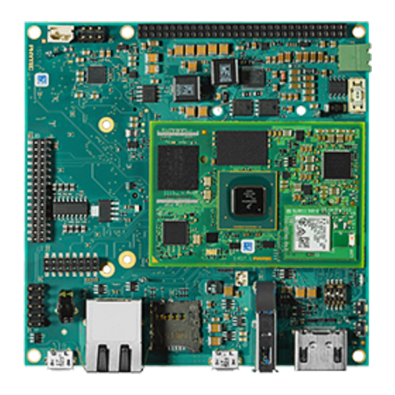
L-863e.A2 phyCORE-i.MX 8M / phyBOARD-Polaris (1497.3 / 1501.2) Hardware Manual 21.4 Block Diagram FIGURE 8: phyBOARD-Polaris Block Diagram © PHYTEC Messtecknik GmbH... - Page 68 L-863e.A2 phyCORE-i.MX 8M / phyBOARD-Polaris (1497.3 / 1501.2) Hardware Manual 22 phyBOARD-Polaris Components Note For easy reference, Pin 1 for each component has been highlighted. 22.1 phyBOARD-Polaris Component Placement Diagram FIGURE 9: phyBOARD-Polaris Components (Top) © PHYTEC Messtecknik GmbH...
- Page 69 L-863e.A2 phyCORE-i.MX 8M / phyBOARD-Polaris (1497.3 / 1501.2) Hardware Manual FIGURE 10: phyBOARD-Polaris Components (Bottom) 22.2 phyBOARD-Polaris Component Overview The phyBOARD-Polaris features many different interfaces and is equipped with the components listed in table phyBOARD-Polaris Connectors and Pin Header. For a more detailed description of each component, refer to the appropriate section listed in the table below. phyBOARD-Polaris Components (Top)
- Page 70 L-863e.A2 phyCORE-i.MX 8M / phyBOARD-Polaris (1497.3 / 1501.2) Hardware Manual Reference Designator Description Section PCI Express connector (Mini PCI PCIe Express) Expansion connector (2×30 socket Expansion Connector connector 2 mm pitch) UART RS-232 with RTS and CTS, or RS-485 UART (UART3 2×5 pin header 2.54 mm...
- Page 71 L-863e.A2 phyCORE-i.MX 8M / phyBOARD-Polaris (1497.3 / 1501.2) Hardware Manual Warning Ensure that all module connections do not exceed their expressed maximum voltage or current. Maximum signal input values are indicated in the corresponding controller User's Manual/Data Sheets. As damage...
- Page 72 Warning Due to the small footprint of the solder jumpers (J), PHYTEC does not recommend manual jumper modifications. This may also render the warranty invalid. Only the removable jumper (JP) is described in this section. Contact our sales team if you need jumper configurations different from the default configuration.
- Page 73 L-863e.A2 phyCORE-i.MX 8M / phyBOARD-Polaris (1497.3 / 1501.2) Hardware Manual 23 phyBOARD-Polaris SBC Component Detail This section provides a more detailed look at the phyBOARD‑Polaris components. Each subsection details a particular connector/interface and associated jumpers for configuring that interface. ...
-
Page 74: Rtc Backup Supply
L-863e.A2 phyCORE-i.MX 8M / phyBOARD-Polaris (1497.3 / 1501.2) Hardware Manual FIGURE 12: Power Supply Connector (X33) The phyBOARD‑Polaris is available with one power supply connector, a 2-pole Phoenix Contact MINI COMBICON base strip 3.5 mm connector (X33) suitable for a single 24 V supply voltage. The required current load capacity for all... - Page 75 L-863e.A2 phyCORE-i.MX 8M / phyBOARD-Polaris (1497.3 / 1501.2) Hardware Manual FIGURE 13: RTC Hold Time (at 25 C) However, this can not be guaranteed. The theoretical value is far below the measurement. The following table shows the calculation: TABLE 42: X33 Pin Assignment Calculation of the RTC backup supply time @ 25 deg...
- Page 76 L-863e.A2 phyCORE-i.MX 8M / phyBOARD-Polaris (1497.3 / 1501.2) Hardware Manual 23.4 UART (X8 and X9) FIGURE 14: UART Connector (X9) The phyCORE-i.MX 8M supports up to 4 UART units. On the phyBOARD-Polaris, TTL level signals of UART1 and UART3 (the standard console) are routed to expansion connector X8 (see...
- Page 77 L-863e.A2 phyCORE-i.MX 8M / phyBOARD-Polaris (1497.3 / 1501.2) Hardware Manual Interface Pin # Signal Interface Pin # Signal 23.4.1 UART Debug Interface The main debug interface is UART1. The UART is connected to a UART-to-USB Converter (U66) via a Multiplexer (U61).
- Page 78 L-863e.A2 phyCORE-i.MX 8M / phyBOARD-Polaris (1497.3 / 1501.2) Hardware Manual TABLE 44: X1 Pin Assignment Interface Pin # Signal name Signal Type Signal Level Description MDCT2 Analog center tap transformer Pair 2 MD2- Ethernet Analog Pair 2- MD2+ Ethernet Analog...
- Page 79 L-863e.A2 phyCORE-i.MX 8M / phyBOARD-Polaris (1497.3 / 1501.2) Hardware Manual 23.5.1 Ethernet Design Consideration The data lanes should be routed with a differential impedance of 100 Ohm. The center taps of each pair's transformer have to be connected to GND through a 100nF capacitor. The LED pins are open-drain outputs of the SOM without a resistor, so they should be connected to the cathodes of the LEDs through a resistor.
- Page 80 L-863e.A2 phyCORE-i.MX 8M / phyBOARD-Polaris (1497.3 / 1501.2) Hardware Manual Interface Pin # Signal name Signal Type Signal Level Description X_USB1_DN Analog USB 2.0 Negative Lane X_USB1_DP Analog USB 2.0 Positive Lane X_USB1_ID Analog ID Pin of USB OTG Port...
- Page 81 L-863e.A2 phyCORE-i.MX 8M / phyBOARD-Polaris (1497.3 / 1501.2) Hardware Manual Interface Pin # Signal name Signal Type Signal Level Description USB_HUB_DN1_D+ Analog USB High-Speed Data positive Ground USB_HUB_DN1_SSR Analog USB SuperSpeed X-_CON Receive Data negative USB_HUB_DN1_SSR Analog USB SuperSpeed X+_CON...
- Page 82 L-863e.A2 phyCORE-i.MX 8M / phyBOARD-Polaris (1497.3 / 1501.2) Hardware Manual 23.6.2 USB Debug (X30) FIGURE 17: USB Debug with LED (X30 / D34) The phyBOARD-Polaris is equipped with a USB Debug interface for downloading program code into the external flash, internal controller RAM, or for debugging programs currently executing.
- Page 83 L-863e.A2 phyCORE-i.MX 8M / phyBOARD-Polaris (1497.3 / 1501.2) Hardware Manual Interface Pin # Signal name Signal Type Signal Level Description SHIELD1 Shield connected to Ground over 2,2 nF parallel to 1 MOhm SHIELD2 Shield connected to Ground over 2,2 nF...
- Page 84 L-863e.A2 phyCORE-i.MX 8M / phyBOARD-Polaris (1497.3 / 1501.2) Hardware Manual 23.7 Secure Digital Memory Card / MultiMedia Card (X4) FIGURE 18: SD / MM Card Interface (X4) The phyBOARD‑Polaris provides a standard microSDHC card slot at X4 for use with SD/MMC interface cards. It allows for a fast, easy connection to peripheral devices like SD and MMC cards.
- Page 85 L-863e.A2 phyCORE-i.MX 8M / phyBOARD-Polaris (1497.3 / 1501.2) Hardware Manual Interface Pin # Signal name Signal Type Signal Level Description Ground SD2_DATA0_EXT 1.8 V / 3.3 V Data Lane 0 SD2_DATA1_EXT 1.8 V / 3.3 V Data Lane 1 X_SD2_CD_B 1.8 V / 3.3 V...
- Page 86 L-863e.A2 phyCORE-i.MX 8M / phyBOARD-Polaris (1497.3 / 1501.2) Hardware Manual 23.8 PCIe (X6) FIGURE 19: PCIe Interface (X6) The 1-lane PCI express interface provides PCIe Gen. 2.0 functionality, which supports 5 Gbit/s operations. The interface is fully backward compatible with the 2.5 Gbit/s Gen. 1.1 specification. Various control signals are implemented with GPIOs.
- Page 87 L-863e.A2 phyCORE-i.MX 8M / phyBOARD-Polaris (1497.3 / 1501.2) Hardware Manual Interface Pin # Signal name Signal Type Signal Level Description X_SAI1_TXD7/ 3.3 V RSVD2 BOOT_CFG15 VCC_1V5 1.5 V Supply miniPCIe_nCLKREQ 3.3 V Inverted Clock Request Ground miniPCIe_REFCLK10 PCIe Ref. Clock...
- Page 88 L-863e.A2 phyCORE-i.MX 8M / phyBOARD-Polaris (1497.3 / 1501.2) Hardware Manual Interface Pin # Signal name Signal Type Signal Level Description X_PCIE2_RXN_N PCIe Analog SOM Receive Negative Lane VCC_3V3 3.3 V Supply X_PCIE2_RXN_P PCIe Analog SOM Receive Positive Lane Ground Ground VCC_1V5 1.5 V Supply...
- Page 89 L-863e.A2 phyCORE-i.MX 8M / phyBOARD-Polaris (1497.3 / 1501.2) Hardware Manual Interface Pin # Signal name Signal Type Signal Level Description VCC_3V3 3.3 V Supply Ground VCC_1V5 1.5 V Supply Ground VCC_3V3 3.3 V Supply Ground Ground 23.8.1 PCIe Design Considerations 100nF AC-Coupling capacitors are placed at the output of the phyCORE-i.MX 8M in series to the TX-Lanes.
- Page 90 L-863e.A2 phyCORE-i.MX 8M / phyBOARD-Polaris (1497.3 / 1501.2) Hardware Manual 23.9 Camera Connectivity (X10 and X11) FIGURE 20: phyCAM-M MIPI CSI-2 Camera Interfaces (X10 and X11) The phyCORE-imMX 8M on the phyBOARD-Polaris offers 2 independent interfaces to connect digital camera boards with the MIPI CSI-2 interface.
- Page 91 L-863e.A2 phyCORE-i.MX 8M / phyBOARD-Polaris (1497.3 / 1501.2) Hardware Manual X_MIPI_CSI1_D1_N MIPI CSI-2 Analog MIPI-CSI-2 Data 1 Negative Lane Ground X_MIPI_CSI1_CLK_P MIPI CSI-2 Analog MIPI-CSI-2 Clock Positive Lane X_MIPI_CSI1_CLK_N MIPI CSI-2 Analog MIPI-CSI-2 Clock Negative Lane Ground X_MIPI_CSI1_D2_P MIPI CSI-2...
- Page 92 L-863e.A2 phyCORE-i.MX 8M / phyBOARD-Polaris (1497.3 / 1501.2) Hardware Manual CSI1_I2C_ADR GPIO 3.3 V Choose the I2C address of the Camera CSI1_ nRESET GPIO 3.3 V CSI1_VCC_SELECT GPIO 3.3 V Interface voltage selection Ground VCC_CAM_CSI1 Supply of Camera VCC_CAM_CSI1 Supply of Camera...
- Page 93 L-863e.A2 phyCORE-i.MX 8M / phyBOARD-Polaris (1497.3 / 1501.2) Hardware Manual X_MIPI_CSI2_D2_P MIPI CSI-2 Analog MIPI-CSI-2 Data 2 Positive Lane X_MIPI_CSI2_D2_N MIPI CSI-2 Analog MIPI-CSI-2 Data 2 Negative Lane Ground X_MIPI_CSI2_D3_P MIPI CSI-2 Analog MIPI-CSI-2 Data 3 Positive Lane X_MIPI_CSI2_D3_N MIPI CSI-2...
- Page 94 R542 has to be mounted for this to be possible. General information and design guidelines for PHYTEC camera interfaces can be found here: https:// www.phytec.de/fileadmin/user_upload/downloads/Manuals/L-748e_10.pdf → phyCAM Concept and Design-In Specific information for each PHYTEC camera module can be found on that module's download page: https:// www.phytec.de/produkte/embedded-imaging/phycam/ © PHYTEC Messtecknik GmbH...
- Page 95 L-863e.A2 phyCORE-i.MX 8M / phyBOARD-Polaris (1497.3 / 1501.2) Hardware Manual 23.10 HDMI (X32) FIGURE 21: HDMI Connector (X32) The phyBOARD‑Polaris provides a High-Definition Multimedia Interface (HDMI) which is compliant with HDMI 2.0a and HDCP 1.4/2.2. It supports one display at a maximum pixel clock of up to 596 MHz and a maximum resolution of 4096x2160 at 60Hz.
- Page 96 L-863e.A2 phyCORE-i.MX 8M / phyBOARD-Polaris (1497.3 / 1501.2) Hardware Manual TABLE 52: X32 Pin Assignment Interface Pin # Signal Name Signal Type Signal Level Description X_HDMI_TX_P_LN_2 HDMI Analog HDMI TX Data 2 Positive Lane Ground X_HDMI_TX_M_LN_2 HDMI Analog HDMI TX Data 2...
- Page 97 L-863e.A2 phyCORE-i.MX 8M / phyBOARD-Polaris (1497.3 / 1501.2) Hardware Manual X_HDMI_DDC_SDA HDMI DDC Data Ground VCC_5V_HDMI 5 V Supply for HDMI Device X_HDMI_AUX_N HPD/ HEAC- 5V / 3.3V Hot Plug detect/ Audio Return Channel Negative Lane SHIELD_1 Shield connected to Ground over 2,2...
- Page 98 L-863e.A2 phyCORE-i.MX 8M / phyBOARD-Polaris (1497.3 / 1501.2) Hardware Manual 23.11 Audio Interface (X14 and X15) FIGURE 22: Speaker Connection (X14) / Line In - Line Out (X15) The audio interface provides a method of exploring and using i.MX 8M's audio capabilities. The phyBOARD-Polaris is populated with an audio codec at U60.
- Page 99 L-863e.A2 phyCORE-i.MX 8M / phyBOARD-Polaris (1497.3 / 1501.2) Hardware Manual LINE_IN_L Audio Analog Line In left channel LINE_IN_R Audio Analog Line In right channel AGND Analog Ground AGND Analog Ground HP_OUT_L Audio Analog Headphone output left HP_OUT_R Audio Analog Headphone output right 23.12 Audio/Video Connectors (X16 and X18)
- Page 100 L-863e.A2 phyCORE-i.MX 8M / phyBOARD-Polaris (1497.3 / 1501.2) Hardware Manual while X18 provides signals for audio and touch screen connectivity as well as an I2C bus and additional control signals. The tables below show the pin assignment of connectors X16 and X18.
- Page 101 L-863e.A2 phyCORE-i.MX 8M / phyBOARD-Polaris (1497.3 / 1501.2) Hardware Manual Interface Pin # Signal Name Signal Type Signal Level Description X_MIPI_DSI_D0_N MIPI DSI Analog MIPI DSI Data 0 Negative Lane TABLE 56: X18 Pin Assignment Interface Pin # Signal Name...
- Page 102 L-863e.A2 phyCORE-i.MX 8M / phyBOARD-Polaris (1497.3 / 1501.2) Hardware Manual Interface Pin # Signal Name Signal Type Signal Level Description X_SAI5_RXD1 SAI5 3.3 V RXD1 X_SAI5_MCLK SAI5 3.3 V MCLK X_SAI5_RXD0 SAI5 3.3 V RXD0 Ground X_I2C2_SDA 3.3 V Data...
- Page 103 L-863e.A2 phyCORE-i.MX 8M / phyBOARD-Polaris (1497.3 / 1501.2) Hardware Manual 23.13 Expansion Connector (X8) FIGURE 24: Expansion Connector (X8) The expansion connector X8 provides an easy way to add other functions and features to the phyBOARD‑Polaris. Standard interfaces such as QSPI, USB, SPDIF, JTAG, UART, SPI, and I C are available at the expansion connector.
- Page 104 L-863e.A2 phyCORE-i.MX 8M / phyBOARD-Polaris (1497.3 / 1501.2) Hardware Manual Interface Pin # Signal Name Signal Type Signal Level Description X_ECSPI1_MOSI 3.3 V MOSI X_ECSPI1_MISO 3.3 V MISO X_ECSPI1_SCLK 3.3 V Clock Ground UART1_RX_EXP UART 3.3 V SOM Receive X_I2C2_SDA 3.3 V...
- Page 105 L-863e.A2 phyCORE-i.MX 8M / phyBOARD-Polaris (1497.3 / 1501.2) Hardware Manual Interface Pin # Signal Name Signal Type Signal Level Description X_SPDIF_RX SPDIF 3.3 V SOM receive X_SPDIF_EXT_CLK SPDIF 3.3 V X_NAND_DATA07 GPIO 3.3 V Ground X_NAND_DATA06 GPIO 3.3 V UART3_RXD_EXP UART 3.3 V...
- Page 106 L-863e.A2 phyCORE-i.MX 8M / phyBOARD-Polaris (1497.3 / 1501.2) Hardware Manual Interface Pin # Signal Name Signal Type Signal Level Description X_NAND_DATA00 GPIO 3.3 V Only available when SOM is without NOR Flash X_NAND_READY_B GPIO 3.3 V Ground X_NAND_CE0_B GPIO 3.3 V...
- Page 107 L-863e.A2 phyCORE-i.MX 8M / phyBOARD-Polaris (1497.3 / 1501.2) Hardware Manual Interface Pin # Signal Name Signal Type Signal Level Description VCC_5V_REG 5.0 V Supply 23.14 Multicolor (RGB) LED (D11) The phyBOARD-Polaris provides one multicolor (RGB) LED (D11) (see phyBOARD-Polaris Components (Top)).
- Page 108 L-863e.A2 phyCORE-i.MX 8M / phyBOARD-Polaris (1497.3 / 1501.2) Hardware Manual 23.15 Switches FIGURE 25: phyBOARD-Polaris Switch Locations 23.15.1 Boot Switch (S1) The phyBOARD‑Polaris has three defined boot sources which can be selected with DIP switch S1: TABLE 59: Boot Switch Configuration Options (S1)
- Page 109 L-863e.A2 phyCORE-i.MX 8M / phyBOARD-Polaris (1497.3 / 1501.2) Hardware Manual 23.15.2 ystem Reset Button (S2) The phyBOARD‑Polaris is equipped with a system reset button at S2. Pressing this button will toggle the X_nRESET_IN pin (X31 Pin A64) of the phyCORE SOM low, causing the module to reset with a complete power cycle.
- Page 110 L-863e.A2 phyCORE-i.MX 8M / phyBOARD-Polaris (1497.3 / 1501.2) Hardware Manual 24 Additional System Level Hardware Information 24.1 I C Connectivity The I2C1 interface of the i.MX 8M is only available on the phyCORE module and is not connected to the phyBOARD‑Polaris. The table below provides a list of the connectors and pins with I...
- Page 111 L-863e.A2 phyCORE-i.MX 8M / phyBOARD-Polaris (1497.3 / 1501.2) Hardware Manual Board Prod. No. Device Address used (7 MSB) Onboard miniPCIe Con. (X6) check your miniPCIe card (! SMBus) Display Adapter PEB_AV_09 A/V-CON. (X18) with PEB- 0x2C AV-09 © PHYTEC Messtecknik GmbH...
-
Page 112: Revision History
L-863e.A2 phyCORE-i.MX 8M / phyBOARD-Polaris (1497.3 / 1501.2) Hardware Manual 25 Revision History TABLE 62: Revision History Release Date Version # Changes in this manual Preliminary Manual Describes the phyCORE‑i.MX 8M 25.10.2019 L-863e.A0 SOM Version: 1497.2 Describes the phyBOARD-Polaris PCB Version: 1501.2 14.05.2020...
Need help?
Do you have a question about the L-863e.A2 phyCORE-i.MX 8M and is the answer not in the manual?
Questions and answers