Table of Contents
Advertisement
Quick Links
Advertisement
Table of Contents

Subscribe to Our Youtube Channel
Related Manuals for Toa NF-2S


Summary of Contents for Toa NF-2S
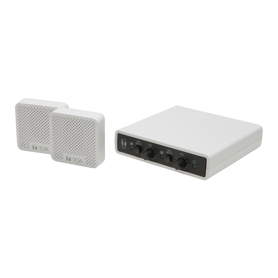
- Page 1 INSTRUCTION MANUAL WINDOW INTERCOM SYSTEM NF-2S EXPANSION SET NF-CS1 Base Unit Sub-Unit Distributor Thank you for purchasing TOA’s Window Intercom System. Please carefully follow the instructions in this manual to ensure long, trouble-free use of your equipment.
-
Page 2: Table Of Contents
3. FEATURES ..........................5 4. USAGE PRECAUTIONS ......................6 5. INSTALLATION PRECAUTIONS ..................6 6. NOMENCLATURE ........................7 6.1. NF-2S ..........................7 6.2. NF-CS1 ..........................11 7. CONNECTIONS ........................12 7.1. Basic System Configuration ..................... 12 7.2. Connection of Commercially Available Headsets ............ -
Page 3: Safety Precautions
• Should the following irregularity be found during use, immediately switch off the power, disconnect the power supply plug from the AC outlet and contact your nearest TOA dealer. Make no further attempt to operate the unit in this condition as this may cause fire or electric shock. - Page 4 Applicable to NF-2S only • Use the unit only with the voltage specified on the unit. Using a voltage higher than that which is specified may result in fire or electric shock. • Do not cut, kink, otherwise damage nor modify the power supply cord. In addition, avoid using the power cord in close proximity to heaters, and never place heavy objects -- including the unit itself -- on the power cord, as doing so may result in fire or electric shock.
-
Page 5: General Description
2. GENERAL DESCRIPTION [NF-2S] Consisting of one Base Unit and two Sub-Units, the NF-2S Window Intercom system is designed to relieve problems in understanding face-to-face conversations through a partition or face masks. Since the Sub-Units’ built-in magnets allow them to be easily attached to both sides of a partition, they can be used even in locations without ample mounting space. -
Page 6: Usage Precautions
NF-CS1 and NF-2S. • Up to three Sub-Units (two Distributors) can be connected to each of the NF-2S Base Unit’s A and B Sub-Unit jacks, including the Sub-Unit supplied with the NF-2S. Do not connect more than three Sub-Units at one time. -
Page 7: Nomenclature
6. NOMENCLATURE 6.1. NF-2S 6.1.1. Base Unit [Front] 1. Power indicator (green) 3. Mute buttons Lights when the Power switch (5) is turned Used to mute the Sub-Unit microphones ON, and extinguishes when turned OFF. connected to the Sub-Unit jacks A (8), B (7), or headset microphones. - Page 8 [Rear] 5. Power switch 8. Sub-Unit jack A Press to turn ON the power to the unit, and Connect the Sub-Units using the dedicated press again to turn the power OFF. cable. When using the NF-CS1, use the dedicated 6. Socket for AC adapter cable to connect the Distributor to this jack.
- Page 9 10. DIP switch This switch allows selection of the device being connected to Sub-Unit jack A (8), and enables/disables the low-cut filter of the Sub-Unit speaker. • Switch 1 [ ] Selects type of device being connected to Sub-Unit jack A (8). Note Be sure the Power is turned OFF before performing this operation.
- Page 10 6.1.2. Sub-Unit [Front] [Rear] [Bottom] 1. Speaker 4. Rubber feet Outputs the voice signal picked up by the Reduce the transmission of vibration to the other paired Sub-Unit. Sub-Unit. Do not remove these rubber feet. 2. Microphone 5. Cable connector Picks up voice sounds, which are then output Connects to the Base Unit or Distributor by from the other paired Sub-Unit.
-
Page 11: Nf-Cs1
Cable connector or another Distributor’s I/O connector. 6.2.2. Sub-Unit These are identical to the Sub-Units that come with the NF-2S. (See "Sub-Unit" on p. 10.) Although their labels may appear slightly different from those of the NF-2S’s Sub-Units, operation and performance are exactly the same. -
Page 12: Connections
7. CONNECTIONS 7.1. Basic System Configuration The basic system configuration of NF-2S is as follows. Sub-Unit (bottom) Sub-Unit (bottom) Dedicated cables (accessories) Base Unit (rear) To AC mains Power cord* AC adapter* (accessory) (accessory) 1. AC adapter connection 2. Sub-Unit connection... -
Page 13: Connection Of Commercially Available Headsets
7.2. Connection of Commercially Available Headsets When using commercially available headsets, connect only to Sub-Unit jack A and turn ON switch 1 of the DIP switch. Please note that the Sub-Unit or NF-CS1 Distributor cannot be connected to Sub-Unit jack A while switch 1 is ON. -
Page 14: Connection Of Mute Switch
7.3. Connection of Mute Switch Any commercially available push-button switch can be connected to the external control input terminal. Note If the external mute function is not to be used, do not connect any switch to the external control input terminal. -
Page 15: Sub-Unit Expansion
To prevent howling, ensure at least 1 m distance between connected Sub-Units. Connection Example: One Distributor (and two Sub-Units) connected to Sub-Unit jack A and two Distributors (and three Sub-Units) connected to Sub-Unit jack B. (Use of one NF-2S and three NF-CS1s.) Sub-Unit Sub-Unit... -
Page 16: Installation
8. INSTALLATION 8.1. Base Unit Installation When placing the Base Unit on a desk or similar surface, attach the supplied rubber feet to the circular indents in the Base Unit’s bottom surface. 8.2. Sub-Unit Installation 8.2.1. Mounting on both sides of a partition Attach the Sub-Units to both sides of a partition by sandwiching it between the magnets built into their rear panels. - Page 17 8.2.2. Use of the Metal Plates Use the supplied metal plates to mount the Sub-Units in the following cases: • When the partition onto which the Sub-Units are to be mounted is over 10 mm (0.39") in thickness. • When the two Sub-Units are not to be magnetically attached to each other. •...
-
Page 18: Changing Audio Output Settings
8.2.3. For cable arrangement Cables can be neatly arranged during installation by using the supplied mounting bases and zip ties. Sub-Unit Mounting base Zip tie After securing the cables, cut the zip ties at the base. Partition 9. CHANGING AUDIO OUTPUT SETTINGS Audio output settings can be changed by switching ON switch 2 of the DIP switch. -
Page 19: Volume Adjustment
The NF-2S utilizes software based on the Open Source Software license. If more detailed information regarding the Open Source Software employed by the NF-2S is required, please download it from the above download site. Also, no information will be provided about the actual contents of the source... -
Page 20: Specifications
Rubber foot for Base Unit ..........4 Mounting base ..............4 Zip tie ................4 No AC adapter and power cord are supplied with the version W. For usable AC adapter and power cord, consult your nearest TOA dealer. • Optional products 5m Extension cable: YR-NF5S... -
Page 21: Nf-Cs1
Note: The design and specifications are subject to change without notice for improvement. • Accessories Dedicated cable (4 pins, 2 m or 6.56 ft) ......2 Metal plate ..............1 Mounting base ..............4 Zip tie ................4 URL: https://www.toa.jp/ 202203...
Need help?
Do you have a question about the NF-2S and is the answer not in the manual?
Questions and answers