Toa N-8000MI CE Installation Manual
Multi interface unit
Hide thumbs
Also See for N-8000MI CE:
- Installation manual (12 pages) ,
- Specifications (2 pages) ,
- Operating instructions manual (269 pages)
Table of Contents
Advertisement
Quick Links
MULTI INTERFACE UNIT
TABLE OF CONTENTS
1. SAFETY PRECAUTIONS ............................. 2
2. GENERAL DESCRIPTION ........................... 5
3. FEATURES ................................................... 5
4. SPECIFICATIONS ........................................ 6
5. SYSTEM CONFIGURATION EXAMPLE ..... 7
6. NOMENCLATURE AND FUNCTIONS ......... 8
Front .............................................................. 8
Rear ............................................................... 8
Thank you for purchasing TOA's Multi Interface Unit.
Please carefully follow the instructions in this manual to ensure long, trouble-free use of your equipment.
N-8000MI CE, N-8000MI CE-GB
INSTALLATION MANUAL
7. INSTALLATION ............................................ 9
7.1. Equipment Rack Mounting ...................... 9
7.2. Desk-Top Installation ............................ 11
8. WIRING ....................................................... 12
8.1. Connection Diagram ............................. 12
8.2. Type of Cable ....................................... 15
8.3. Connector Connection ......................... 15
9. ACCESSORIES .......................................... 16
Advertisement
Table of Contents

Subscribe to Our Youtube Channel
Related Manuals for Toa N-8000MI CE


Summary of Contents for Toa N-8000MI CE
-
Page 1: Table Of Contents
6. NOMENCLATURE AND FUNCTIONS ..8 8.3. Connector Connection ......15 Front .............. 8 9. ACCESSORIES .......... 16 Rear ............... 8 Thank you for purchasing TOA's Multi Interface Unit. Please carefully follow the instructions in this manual to ensure long, trouble-free use of your equipment. -
Page 2: Safety Precautions
AC outlet and · When connecting the unit's power cord to an AC contact your nearest TOA dealer. Make no further outlet, use the AC outlet with current capacity attempt to operate the unit in this condition as this allowable to the unit. - Page 3 Indique une situation risquant d’entraîner des fiche du cordon d’alimentation de la prise secteur blessures graves, voire la mort, en cas de et contacter le représentant TOA le plus proche. mauvaise manipulation. Ne pas essayer pas d’utiliser l’appareil dans ces conditions sous peine de provoquer un incendie ou une électrocution.
- Page 4 • Respecter les instructions ci-dessous pour monter ATTENTION l’appareil en bâti. Risque d’incendie ou de blessure corporelle. Indique une situation risquant d’entraîner des · Installer le bâti sur un sol stable. Le fixer à l’aide blessures moyennement graves ou mineures, et/ de boulons d’ancrage ou prendre des mesures ou des dommages matériels.
-
Page 5: General Description
2. GENERAL DESCRIPTION The N-8000MI is a multi interface unit designed for use with TOA’s packet intercom system (IP network- compatible intercom system) that employs the packet audio technology*. Connecting the multi interface to a local area network permits the ideal system for in-house or wide-area information transmission applications, such as paging, periodical broadcasts, and background music broadcasts, to be built between the multi interface and IP intercom exchange or other multi interface unit. -
Page 6: Specifications
4. SPECIFICATIONS Number of Units Connectable to LAN: Maximum 192 (a total of Exchanges and Multi Interface Units) Speech Link Capacity 2 links Speech (through the PBX or tie-line): Maximum 2 links Audio input: Maximum 2 links Audio output: Maximum 2 links Note The above links can be simultaneously used. -
Page 7: System Configuration Example
5. SYSTEM CONFIGURATION EXAMPLE To LAN N-8000MI EXES-2000 EXES-6000 BGM player, digital Amplifier announcer, or other sound source Contact input Contact output (door remote control) Speaker Having 2 channels each for audio input and output, and 16 contacts each for control input and output, the N-8000MI performs the following interface functions*. -
Page 8: Nomenclature And Functions
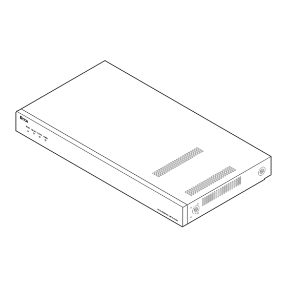
6. NOMENCLATURE AND FUNCTIONS [Front] 1 2 3 4 5 00-05-F9-FF-00-00 1. Reset key [RESET] 4. Power indicator [POWER] (Green) Pressing this key reactivates the exchange. Lights when power is supplied to the unit. 2. LNK/ACT indicator [LNK/ACT] (Green) 5. MAC address Lights when connected to a network, and flashes This is the address* used by the unit. -
Page 9: Installation
7. INSTALLATION The N-8000MI can be installed in any of two ways: Equipment rack mounting and Desk-top installation. 7.1. Equipment Rack Mounting A) Elevated Operating Ambient - If installed in a closed or multi-unit rack assembly, the operating ambient temperature of the rack environment may be greater than room ambient. Therefore, consideration should be given to installing the equipment in an environment compatible with the maximum ambient temperature (Tma) specified by the manufacturer. - Page 10 7.1.2. Caution when installing the unit CAUTION Do not block the ventilation slots in the unit’s cover. Doing so may cause heat to build up inside the unit and result in fire. Do not stack up 3 units or more. If 2 or more units are mounted in the Equipment rack, be sure to mount the perforated panel of 1 U size (PF-013B) or more above and below every 2 units.
-
Page 11: Desk-Top Installation
7.2. Desk-Top Installation When installing the N-8000MI on a desk, Machine screw M4 x 20 secure the supplied plastic feet to the unit’s (accessory) bottom using the supplied tapping screws. Vis de mécanique M4 x 20 (accessoire) Installation sur un bureau Plastic foot N-8000MI Pour installer l’unité... -
Page 12: Wiring
8. WIRING 8.1. Connection Diagram N-8000MI Be sure to ground this terminal unless the unit 9P removable terminal connects to a PBX. plug (accessory) To AC mains or a UPS (Uninterruptible power supply)* Contact input signals Contact output signals Note If there is a danger of lightning strikes, insert an appropriate surge arrester into the power... - Page 13 N-8000MI RJ-45 connector 8P removable terminal plug To network (accessory) Mini-clamp connector (accessory) To the tie-line unit of intercom system or the PBX's OD trunks Control input Line input * Line input * Note Control input You can use only either of the Audio input/output CH1 terminals BGM player, etc.
- Page 14 [Connecting to the PBX's OD trunk] Connect the PBX's transmitting line to the unit's RX terminal, and the PBX's receiving line to the TX terminal. Also connect the PBX's M (Mouth) line to the unit's E (Ear) terminal, and the PBX's E line to the M terminal. N-8000MI's PBX interface terminal To PBX's ground point To PBX OD trunk's M and E lines...
-
Page 15: Type Of Cable
8.2. Type of Cable The types of cables are to be determined according to the following conditions. • Twisted pair wires (such as those used for electronic push-button telephone) are to be used for wiring to the audio input/output terminals and PBX interface terminal. •... -
Page 16: Accessories
For example, when placing the CD in the "d" drive, d:\index.html Version update information • Download our TOA Products Data, web site (https://www.toa-products.com/international/) to get the up-to-date version for N-8000 software, firmware, and Instruction manuals. • The software version number can be confirmed using the Help menu.
Need help?
Do you have a question about the N-8000MI CE and is the answer not in the manual?
Questions and answers