Toa N-8000EX Operating Instructions Manual
N-8000 series packet intercom system
Hide thumbs
Also See for N-8000EX:
- Installation manual (20 pages) ,
- Specifications (12 pages) ,
- Supplementary manual (8 pages)

Related Manuals for Toa N-8000EX


Summary of Contents for Toa N-8000EX
- Page 1 OPERATING INSTRUCTIONS PACKET INTERCOM SYSTEM N-8000 SERIES Thank you for purchasing TOA's Packet Intercom system. Please carefully follow the instructions in this manual to ensure long, trouble-free use of your equipment.
-
Page 2: Table Of Contents
TABLE OF CONTENTS SAFETY PRECAUTIONS (For N-8000EX and N-8000MI) OPERATING INSTRUCTIONS CONFIGURATION Chapter 1 : GENERAL DESCRIPTION 1. GENERAL DESCRIPTION 2. FEATURES ... 1-2 3. HANDLING PRECAUTIONS 4. SPECIFICATIONS 5. SYSTEM CONFIGURATION 5.1. System Configuration Example 5.1.1. Exchange 5.1.2. Peripheral components 5.1.3. - Page 3 7. SYSTEM FUNCTION TABLE 7.1. Basic Functions ... 1-28 7.2. Multi Interface Unit's Functions 8. PAGING FUNCTION OUTLINES 8.1. Paging Types 8.1.1. PA paging (Only when the N-8000EX/8000MI is used) 8.1.2. Station paging ... 1-33 8.2. Paging Functions 8.2.1. Zone paging ... 1-34 8.2.2.
- Page 4 9.6.3. Contact bridge function (external contact interlock) 9.6.4. Paging busy input 9.6.5. System diagnosis Chapter 2 : FUNCTIONS AND OPERATION 1. BASIC USAGE 1.1. Calling from a Master Station 1.2. Calling from a Door Station 1.3. Receiving a Call 1.3.1. Receiving a call at the master station 1.3.2.
- Page 5 3.3. Responding to Paging 3.3.1. Automatic response 3.3.2. Zone number designation response 4. OTHER FUNCTIONS AND OPERATION 4.1. Scan Monitor ... 2-29 4.2. PBX Connection (only when the N-8000MI is used) 4.2.1. Calling the PBX extension telephone 4.2.2. Being called from a PBX extension telephone 4.2.3.
- Page 6 3. INSTALLATION OF STATIONS 3.1. When Mounting the Station on a Wall 3.1.1. N-8000MS/8010MS/8500MS 3.1.2. N-8020MS ... 3-8 3.2. On-Wall Mounting 3.2.1. N-8000MS/8010MS/8020MS/8500MS 3.2.2. N-8011MS ... 3-11 3.3. Desk-Top Installation 3.3.1. N-8000MS/8010MS/8020MS/8500MS 3.3.2. N-8011MS ... 3-14 3.4. In-Wall Mounting Using an Electrical Box 3.4.1.
- Page 7 1.4. IP Stations 1.4.1. Network settings 1.4.2. Function settings 1 1.4.3. Function settings 2 1.4.4. Speed dialing ... 4-9 1.4.5. Scan monitor ... 4-10 1.5. Stations 1.5.1. Function settings 1.5.2. Speed dialing ... 4-11 1.5.3. Scan monitor ... 4-11 1.5.4. Paging ...
- Page 8 5. SYSTEM SETTING FUNCTION 5.1. Screen Description ... 5-16 5.2. Menu 5.2.1. File ... 5-17 5.2.2. Setting ... 5-17 5.2.3. Help ... 5-17 5.3. Overall System Configuration Settings 5.3.1. Equipment registration 5.3.2. Station number and type settings 5.3.3. Network communications registration 5.3.4.
- Page 9 2. MENU ITEMS ... 6-2 3. DISPLAYING THE MENU SCREEN 4. NETWORK SETTING ... 6-5 5. OPERATION STATUS DISPLAY 5.1. N-8000EX/8010EX ... 6-6 5.2. N-8000MI ... 6-7 5.3. N-8500MS ... 6-9 5.4. N-8540DS ... 6-11 6. LINE STATUS INDICATION (Only for the Exchange) 7.
- Page 10 N-8000 Software Program 1.3. Unicast vs. Multicast Communications 1.4. Network Paging Restrictions 1.5. Unit Scan and Broadcast Communications Domains 1.6. Sampling Frequency Correction (N-8000EX/8010EX/8000MI only) 2. IF TROUBLE OCCURS: 3. INDICATOR STATUS & TROUBLESHOOTING 4. SPECIFICATIONS 4.1. N-8000EX IP Intercom Exchange 4.2.
-
Page 11: Safety Precautions (For N-8000Ex And N-8000Mi)
• Should the following irregularity be found during use, immediately disconnect the power supply plug from the AC outlet and contact your nearest TOA dealer. Make no further attempt to operate the unit in this condition as this may cause fire or electric shock. - Page 12 · Install the equipment rack on a stable, hard floor. Fix it with anchor bolts or take other arrangements to prevent it from falling down. · To mount the unit on the TOA equipment rack, use the rack mounting hardware supplied with the unit.
-
Page 13: Operating Instructions Configuration
OPERATING INSTRUCTIONS CONFIGURATION This operating instruction consists of Chapter 1 – 8 as follows. Please read the necessary chapter as required. To all users To the person who operates the equipment To the person who installs and wires the equipment To the person who designs and maintains the system To the person who installs and... -
Page 14: Chapter 1 : General Description
Chapter 1 GENERAL DESCRIPTION This chapter describes the Exchange, Multi interface unit and IP station system configurations, station types, and functions of the N-8000 Series Packet Intercom System. -
Page 15: General Description
• System maintenance (verifying operation log and Line supervision) can also be performed with a personal computer and Internet browser. • Both types of exchanges differ in the following points. N-8000EX: Internal 4 links* N-8010EX: Internal 1 link* , external 2 links* •... -
Page 16: Specifications
Audio output: Maximum 2 links Note The above links can be simultaneously used. (Refer to the table on 1-6.) Maximum 160 Maximum 160 (When 80 N-8000EX Exchanges or Multi interface units are connected) 2 outputs 2 outputs Multicast paging: Maximum 4 links Unicast paging:... -
Page 17: System Configuration
N-8500MS * Connecting the station to a PoE (Power over Ethernet) switching hub eliminates the need for an AC adapter. In such a case, connect the switching hub to a UPS. N-8000EX/8010EX (N-8000EX only) To AC Mains N-8011MS N-8020MS N-8000MI... -
Page 18: Exchange
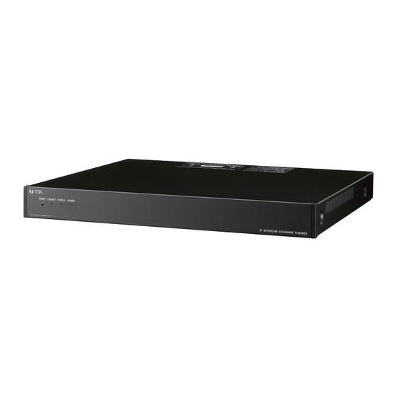
5.2. Component Description 5.2.1. Exchange [N-8000EX IP Intercom Exchange] The Exchange permits connection of up to sixteen N-8000 Series stations and features two outputs for public address paging. The speech links consist of 4 internal links and 8 external links. The exchange is equipped with a networking interface, allowing connection with IP stations, multi interface units, and other IP intercom exchanges. -
Page 19: Peripheral Components
5.2.2. Peripheral components [N-8000MI Multi Interface Unit] Having 2 channels each for audio input and output, and 16 contacts each for control input and output, the N- 8000MI performs the following interface functions*. • Tie-line interface for connection with the EXES-2000 and EXES-6000 systems. •... -
Page 20: Stations
5.2.4. Stations Speech Method Type of Stations Handset Hands- free N-8000MS: Multifunctional Master Station N-8010MS: Standard Master Station N-8011MS: Standard Hands-Free Master Station N-8020MS: Industrial-Use Master Station N-8031MS: Flush-Mount Master Station N-8050DS: Door Station The front operation panel can be inclined 16° from the desk surface by attaching the YC-280 Wall Mounting Bracket to its bottom surface. -
Page 21: Rack Mounting Examples For Exchanges
5.3. Rack Mounting Examples for Exchanges Note: The Exchange N-8000EX in these examples can be replaced with the N-8010EX Exchange. 5.3.1. A 128-line exchange system One CR-273 Equipment Rack is used. Blower unit (BU-412) Terminal board (E-7000TB) Terminal board (E-7000TB) -
Page 22: A 1280-Line Exchange System
5.3.4. A 1280-line exchange system Seven CR-413 Equipment Racks are used. Blower unit (BU-412) Rack No. 1 No. 3 Exchange (N-8000EX) Exchange (N-8000EX) Exchange (N-8000EX) Exchange (N-8000EX) Perforated panel Perforated panel Exchange (N-8000EX) Exchange (N-8000EX) Exchange (N-8000EX) Exchange (N-8000EX) Perforated panel... -
Page 23: Nomenclature And Functions
6. NOMENCLATURE AND FUNCTIONS 6.1. N-8000EX IP Intercom Exchange [Front] 1 2 3 4 5 1. Reset key [RESET] Pressing this key reactivates the exchange. 2. LNK/ACT indicator [LNK/ACT] (Green) Lights when connected to a network, and flashes while transmitting or receiving data. -
Page 24: N-8010Ex Ip Intercom Exchange [Front]
6.2. N-8010EX IP Intercom Exchange [Front] 1 2 3 4 5 1. Reset key [RESET] Pressing this key reactivates the exchange. 2. LNK/ACT indicator [LNK/ACT] (Green) Lights when connected to a network, and flashes while transmitting or receiving data. 3. Status indicator [STATUS] (Red) Continuously lights while data is written to an internal storage medium (FlashMemory), and flashes to indicate such exchange malfunctions as... -
Page 25: N-8000Mi Multi Interface Unit [Front]
6.3. N-8000MI Multi Interface Unit [Front] 1 2 3 4 5 1. Reset key [RESET] Pressing this key reactivates the exchange. 2. LNK/ACT indicator [LNK/ACT] (Green) Lights when connected to a network, and flashes while transmitting or receiving data. 3. Status indicator [STATUS] (Red) Continuously lights while data is written to an internal storage medium (FlashMemory). -
Page 26: N-8500Ms Ip Multifunctional Master Station [Top]
6.4. N-8500MS IP Multifunctional Master Station [Top] 1. Handset Lift the handset for handset conversation. Lifting the handset disconnects both the hands-free microphone and the speaker. 2. Auto-dial key Used to call or register the party to be called. (Refer to 2-9.) 3. -
Page 27: [Rear]
11. Push-to-talk key [PTT] Pressing this key while calling a party by means of a continuous call tone permits a voice call to be made. (Refer to 2-7.) Also, pressing this key during a hands-free conversation establishes a one-way conversation from the party who pressed the key. -
Page 28: [Bottom]
[Bottom] 28. MAC address This is the address* used by the IP station. Since the relationship of each IP station location to its MAC address is established when setting the network attributes, keep track of this relationship for later use. * The inherent address assigned to each network component, expressed in 12-digit hexadecimal notation. -
Page 29: N-8540Ds Ip Door Station [Front]
6.5. N-8540DS IP Door Station [Front] [Top] 1. Speaker Outputs call tones and used for hands-free conversations. 2. Status indicator (Red) Flashes when a call or paging announcement is received, continuously lights during conversation, and is off while in standby mode. The indicator also continuously lights while data is written to an internal storage memory (FlashMemory), and flashes if there is a failure. -
Page 30: N-8000Ms Multifunctional Master Station [Top]
6.6. N-8000MS Multifunctional Master Station [Top] 1. Handset Lift the handset for handset conversation. Lifting the handset disconnects both the hands-free microphone and the speaker. 2. Auto-dial key Used to call or register the party to be called. (Refer to 2-9.) 3. -
Page 31: [Rear]
9. Redial key [REDIAL] Permits the last called number to be dialed. (Refer to p.2-6.) 10. Function key [FUNCTION] Use this key to perform function settings such as assigning call transfer recipients or programming one-touch dialing. 11. Push-to-talk key [PTT] Pressing this key while calling a party by means of a continuous call tone permits a voice call to be made. -
Page 32: [Bottom]
[Bottom] 22. Speaker selector switch [INT.SP/EXT.SP] Used to select either an internal (INT.SP) or an external (EXT.SP) speaker. 23. Microphone Used for hands-free conversation. Note Avoid placing obstacles close to the microphone that might block sound and prevent conversations. Chapter 1: GENERAL DESCRIPTION 24. -
Page 33: N-8010Ms Standard Master Station [Top]
6.7. N-8010MS Standard Master Station [Top] 1. Handset Lift the handset for handset conversation. Lifting the handset disconnects both the hands-free microphone and the speaker. 2. Dial directory Writes the dial registration of the party to be called to this directory. 3. -
Page 34: [Rear]
[Rear] 14. Line connection terminal [LINE] Connects to the exchange. (RJ-11 modular jack) [Bottom] 15. Microphone Used for hands-free conversation. Note Avoid placing obstacles close to the microphone that might block sound and prevent conversations. Chapter 1: GENERAL DESCRIPTION 16. Wall bracket mounting slots Hang the hooks of the mounting bracket to these slots when using the YC-280 Wall Mounting Bracket. -
Page 35: N-8011Ms Standard Hands-Free Master Station [Top]
6.8. N-8011MS Standard Hands-free Master Station [Top] 1. Paging response key [RESP.] Responds to a paging. (Refer to 2. Paging key [CALL] Makes a paging. (Refer to 2-23.) 3. Hold key [HOLD] Places the conversation on hold. (Refer to 2-11.) 4. -
Page 36: [Rear]
[Rear] 12. Line connection terminal [LINE] Connects to the exchange. (RJ-11 modular jack) [Bottom] 13. Microphone Used for hands-free conversation. Note Avoid placing obstacles close to the microphone that might block sound and prevent conversations. Chapter 1: GENERAL DESCRIPTION 14. Wall bracket mounting slots Hang the mounting bracket hooks to these slots when using the YC-290 Wall mounting bracket. -
Page 37: N-8020Ms Industrial-Use Master Station [Top]
6.9. N-8020MS Industrial-Use Master Station [Top] 1. Handset Lift the handset for handset conversation. Lifting the handset disconnects both the hands-free microphone and the speaker. 2. Status indicator (Red) Flashes when a call is received, continuously lights during a conversation, and is off while in standby mode. -
Page 38: [Rear]
[Rear] Protection cover 13. Line connection cable [LINE] Connects to the exchange. (3 m-length cable with RJ-11 modular plug) Note: Do not remove the protection cover. 14. External speaker terminal [EXT.SP.] An external speaker (8 Ω, 0.6 W) can be connected to this terminal. -
Page 39: N-8031Ms Flush-Mount Master Station [Front]
6.10. N-8031MS Flush-Mount Master Station [Front] 1. Status indicator (Red) Flashes when a call is received, continuously lights during a conversation, and is off while in standby mode. The indicator also continuously lights while receiving a paging announcement. 2. Paging key [CALL] Makes a paging. -
Page 40: N-8050Ds Door Station [Front]
14. Handset connection terminals [CN302] A dedicated RS-191 Option Handset can be connected. (Refer to 3-24.) 6.11. N-8050DS Door Station [Front] 1. Speaker Outputs call tones and used for hands-free conversations. 2. Status indicator (Red) Flashes when a call is received, continuously lights during a conversation, and is off while in standby mode. -
Page 41: System Function Table
7. SYSTEM FUNCTION TABLE 7.1. Basic Functions IP stations or the system consisting of Exchanges and stations makes the following functions available. Function Hands-free conversation Handset conversation Conversation PTT conversation Individual call Redialing Recall Call Voice calling Group call Master station call Automatic connection... - Page 42 Function Auto-dialing (N-8000MS/ 8500MS only) Speed Dialing One-touch dialing Mic Off Hold Call hold Call transfer* Group hunting Absence transfer Automatic Transfer Call forwarding Remote Response* Executive Priority* * The stations connected to the N-8010EX Exchange have restrictions on use of these functions. Description The dial operation (up to 20-digit numbers) programmed into the station's auto dialer can be...
- Page 43 Function Zone paging Selectable Paging paging All-call paging Automatic response Paging Zone number Response designation paging Scan Monitor Door Remote Control (Only when the N-8050DS/8540DS is used.) Call- and Talk-Interlocked Contact Output (only when the N-8050DS/8540DS is used) Time-Out Group Blocking Station Speaker Output Setting Ambient Noise Control Description...
-
Page 44: Multi Interface Unit's Functions
7.2. Multi Interface Unit's Functions The addition of the N-8000MI Multi-interface unit makes the following functions available: Function External Input Paging PBX Connection Tie-Line Connection One-shot make output External Equipment Control Make/break output Calling Station Indication/CCTV Interlock Door Remote Control Remote Dial Control Contact Bridge Description... - Page 45 Function Paging Busy Input System Diagnosis Chapter 5: SYSTEM SETTINGS BY SOFTWARE Description Notifies the busy status of connected external PA paging equipment. The Multi interface unit diagnoses the system condition via the network, and provides its results at the contact output terminal as open or closed contact.
-
Page 46: Paging Function Outlines
8.1. Paging Types 8.1.1. PA paging (Only when the N-8000EX/8000MI is used) Connecting PA equipment to the N-8000EX exchange's or N-8000MI multi interface unit's output terminal permits PA paging to be made by dial operation at the station. 8.1.2. Station paging Performing dial operation at a station permits paging to be made to other stations' internal speakers. -
Page 47: Paging Functions
8.2. Paging Functions 8.2.1. Zone paging Calls can be made to one of the pre-programmed zones. For PA paging, assign a PA paging output to the zone number. For station paging, assign a station to the zone number. One of the following three settings can be selected: PA paging only, station paging only, or a combination of PA paging and station paging. -
Page 48: Responding To Paging
PA paging output are connected to. Zone 1 Speaker Building B Zone 2 Zone 3 Speaker (Zone number with 3-digit length) Chapter 1: GENERAL DESCRIPTION Building C Hello, Mr. TOA. Please respond. Zone 2 Hello, Mr. TOA. Please respond to Response 002. 1-35... -
Page 49: Multi Interface Function Outlines
9. MULTI INTERFACE FUNCTION OUTLINES Functions that are available with the use of the N-8000MI Multi interface unit are described below. 9.1. External Input Paging Microphone announcements or background music can be broadcast to any desired channel by connecting a Remote microphone or playback components to the N-8000MI unit. -
Page 50: Pbx Interface (E And M Interface)
9.4. PBX Interface (E and M Interface) Connecting the N-8000MI unit to a PBX permits conversations to be made between the intercom station and the telephone, or paging calls to be initiated from the telephone. The N-8000MI is connected to a standard PBX analog E&M interface using 3 pairs of cables per line. -
Page 51: Contact Input And Output Functions
Chapter 1: GENERAL DESCRIPTION 9.6. Contact Input and Output Functions The following functions can be realized by using the N-8000MI's contact input and output. 9.6.1. External equipment control External equipment can be controlled by a one-shot make signal or a make/break signal provided at the N- 8000MI's contact output through either interlock with received calls or station operation. -
Page 52: Paging Busy Input
Diagnosis is performed at the set time intervals*. Therefore, the diagnosis results are not obtained in real time. The system condition, even if a change occurs, cannot be detected in the intervals from a diagnosis to the next diagnosis. * Diagnosis results are renewed every 20 seconds or less. N-8000EX Chapter 1: GENERAL DESCRIPTION N-8000MI Busy signal... -
Page 53: Chapter 2 : Functions And Operation
Chapter 2 FUNCTIONS AND OPERATION This chapter describes the system functions and operation of the N-8000 Series Packet Intercom System. -
Page 54: Basic Usage
1. BASIC USAGE Operation is the same for both the stations connected to the exchange and the IP stations connected to a LAN. 1.1. Calling from a Master Station Step 1. Dial the number of the station to be called. •... -
Page 55: Calling From A Door Station
1.2. Calling from a Door Station Step 1. Press the call button to call the pre-programmed master station. The calling station's internal speaker sounds an audible call tone. • If the door station is not set to door station mode, a busy tone is heard when the called master station is busy. -
Page 56: Receiving A Call
1.3. Receiving a Call 1.3.1. Receiving a call at the master station Step 1. Responding to a Received Call. 1-1. If the called station is set to Automatic connection mode*, the call tone sounds only once, after which the calling party's voice is heard immediately through the internal speaker. -
Page 57: Conversation Functions And Operation
2. CONVERSATION FUNCTIONS AND OPERATION 2.1. Conversation 2.1.1. Hands-free conversation Permits conversations to be made without holding the handset when another party is called or when a call is received in automatic connection mode. [Ambient Noise Level Measurement] The master station has a function to measure ambient noise level at its installation site, automatically making the internal setting for proper hands-free conversation. -
Page 58: Ptt Conversation
2.1.3. PTT conversation This function makes announcements and conversations possible to areas with a high ambient noise level. Pressing the Push-to-talk key during a conversation enables one-way conversation from the party who pressed the Push-to-talk key. Conversation flow is reversed when the key is released. -
Page 59: Recall
Chapter 2: FUNCTIONS AND OPERATION ] key regardless of whether the call was ] key to perform the Continuous call tone Hello, Mr. TOA. [Example] R e d i a l i n g 0 : 1 0 0 1... -
Page 60: Group Calls
2.2.6. Group calls • When a station is assigned to group call member station, if the station is called, this station (representative station) and all member stations are simultaneously called by a continuous call tone regardless of their call receiving mode settings. •... -
Page 61: Speed Dialing
2.4. Speed Dialing 2.4.1. Auto-dialing (N-8000MS/8500MS only) The dial operation (up to 20-digit numbers) programmed into the station's auto dialer can be performed by one- touch dialing. • Auto Dial keys can be programmed individually at each station. • The contents programmed into each Auto Dial key can be confirmed at each station. -
Page 62: One-Touch Dialing
2.4.2. One-touch dialing The dial operation (up to 20-digit numbers) programmed into the station's [7], [8], [9], [0], or [Off-Hook*] keys can be called by one-touch dialing. * The action to lift up the handset. Notes • Perform one-touch dial programming when using the external dial input terminal on the N-8031MS. -
Page 63: Hold
2.5. Hold 2.5.1. Mic off Disabling the microphone during a conversation places the line on hold. [Mic off] Hold down any key of [0] through [9] continuously during a conversation. [Mic off release] If the key hold down is released, the original conversation is restored. -
Page 64: Call Transfer
2.6. Call Transfer During a conversation, either party can call another station to speak with a third party (temporarily placing the original conversation partner on hold) and then either return to the original conversation or transfer the conversation with the third party to the original conversation partner. Note The stations connected to the N-8010EX will not perform the Call Transfer function. - Page 65 [Transferring calls to a third party] Step 3. To connect the third party to the original conversation partner (who has been placed on hold), either press the Clear key or replace the handset. This permits conversation between the second and third parties.
-
Page 66: Automatic Transfer
Chapter 2: FUNCTIONS AND OPERATION 2.7. Automatic Transfer Note Calls cannot be automatically transferred to the station connected via the multi interface unit. 2.7.1. Group hunting Calls to a busy station are automatically transferred to another designated station. This Group hunting function also applies to the call transfer 2-12) performed during conversation. - Page 67 Programming or erasure can be performed at your station. Function designation number [Programming] [Erasure] [Setting example] Settings can be performed to permit calls to be transferred to designated stations in a cyclical manner. Call received Group hunting No. 62 Notes •...
-
Page 68: Absence Transfer
2.7.2. Absence transfer When no response is made to a call to the station for a set period of time, the call is automatically transferred to another designated station. Calls received during conversation can be transferred. (Refer to The station to which a Absence transfer is to be transferred can be set either by a dialing operation (see below) or using the supplied N-8000 Software program. -
Page 69: Call Forwarding
2.7.3. Call forwarding Calls to stations are automatically transferred to another designated station without sounding a call tone. Two different modes are available: one is call forwarding, in which calls are manually rerouted to the selected station, and the other is time-based call forwarding, which transfer calls only when the preset time is reached. This Call forwarding function also applies to the call transfer The station to which a Call forwarding is to be transferred can be set either by dialing operation (see below 2-18) or using the supplied N-8000 Software program. - Page 70 [Calls to stations set for time-based call forwarding] Step 1. When the preset transfer time is reached, the station's display shows the station (e.g. number 62) has entered the Time-based Call forwarding mode (N-8000MS/8500MS only). Transfer destination station number Transfer destination station name 6 3 M a i n e n t r a n c e Step 2.
-
Page 71: Remote Response
2.8. Remote Response Calls to a station can be answered, provided both stations are assigned to the same group. Up to 16 stations can be set to a Response group. The Remote Response function can only be used while calls are being made by a continuous call tone. The Remote response function cannot be used for answering a group call made by the group call function. - Page 72 [Remote response group new programming] Function designation number [Remote response group member addition] Member station number [Remote response group erasure] [Remote response group member erasure] Member station number Notes • Stations currently set for other Remote Response groups can not establish a different Remote Response group.
-
Page 73: Executive Priority
2.9. Executive Priority If a called station is busy, as indicated by a busy tone, performing Priority operation from a call station transmits a short priority call tone, then forcibly terminates the current conversation, allowing the call to go through. Access to priority call operation or refusal of priority calls can be set individually for each station. Use the supplied N-8000 Software program to perform the setting. -
Page 74: Group Blocking
2.11. Group Blocking Stations can be blocked into groups (up to 31 groups) which can or cannot make calls to each other. Paging zone numbers available among such groups can also be set. Note Use the supplied N-8000 software to set the station groups, calls that can be made among groups, and paging zones that can be mutually called. -
Page 75: Paging Function And Operation
3. PAGING FUNCTION AND OPERATION 3.1. Paging Paging stations are preprogrammed. Paging durations can be limited by preprogramming the time limit (between 10 and 999 seconds in 10-second units) for each exchange or IP station. Note Use the supplied N-8000 Software program to enable or disable the paging operation and to set the paging duration. -
Page 76: Selectable Paging
3.1.2. Selectable paging Paging calls can be made to up to 10 zones. Use the supplied N-8000 Software program to set the paging zones. (Refer to p.5-61.) Step 1. Press the Paging key, then [ Note Enter a zone number with the same digit length (1 – 3 digits) set with the N-8000 Software program. Step 2. -
Page 77: All-Call Paging
3.1.3. All-call paging Paging calls can be made simultaneously to all of the pre-programmed zones. Use the supplied N-8000 Software program to set the paging zones. (Refer to p.5-61.) Step 1. Press the Paging key, followed by he paging zone number 0 (for all-call paging). A paging tone is transmitted to all zones. -
Page 78: External Input Paging (Only When The N-8000Mi Is Used)
3.2. External Input Paging (only when the N-8000MI is used) Activating the control input after connecting the Remote microphone or playback components to the Multi interface unit enables broadcasting to the preprogrammed zone(s). There are two methods of activation: one is to use the Audio input terminal (A in the following figure), and the other is to use the Contact input terminal (B). -
Page 79: Responding To Paging
• Since each paging zone is independent, responding from any station where a paging is audible connects the paged party to the paging party. 5-30, 5-49.) Building B Zone 2 Zone 3 Speaker Chapter 2: FUNCTIONS AND OPERATION Building C Hello, Mr. TOA. Please respond. 2-27... -
Page 80: Zone Number Designation Response
• Station connected to the same exchange as the station assigned to the paged zone or the PA paging output are connected to. Chapter 2: FUNCTIONS AND OPERATION Zone 2 Hello, Mr. TOA. Please respond to Response 002. (Zone number with 3-digit length) -
Page 81: Other Functions And Operation
4. OTHER FUNCTIONS AND OPERATION 4.1. Scan Monitor The station can scan an arbitrary group of pre-programmed stations for auditory monitoring. Stations are monitored in preprogrammed sequence at specified time intervals. Manual control from the monitoring station can also be performed. Up to 16 stations can be programmed to the same monitor group. -
Page 82: Pbx Connection (Only When The N-8000Mi Is Used)
Step 2. Manual Scan 2-1. Stopping and restarting automatic scan To continuously monitor a specified station, press the [0] key when that station is displayed to stop automatic scan operation. Pressing the [0] key again restores automatic scan operation. 2-2. Advancing a scan Pressing the [ ] key advances the scan by one station. -
Page 83: Being Called From A Pbx Extension Telephone
4.2.2. Being called from a PBX extension telephone Dialing the intercom access number as well as the N-8000 system's station number at the PBX extension telephone permits the N-8000 system's station to be called. The method for receiving a call from the PBX extension telephone at the N-8000 system's station is the same as when it is called by another station within the system. -
Page 84: Tie-Line Connection (Only When The N-8000Mi Is Used)
4.3. Tie-Line Connection (only when the N-8000MI is used) Using the Multi interface unit for tie-line connection between the N-8000 Series intercom system exchange and other series intercom system exchanges via 4-wire private lines permits calls, conversations, or paging calls to be mutually made between stations connected to the tie-line connected exchanges. 4.3.1. -
Page 85: Making Paging Calls To Another Intercom System
4.3.3. Making paging calls to another intercom system Step 1. Press the tie-line access number. The called intercom system can be connected. Step 2. After confirming that a dial tone from the connected intercom system is heard, dial the paging operation number of the connected intercom system, and make a paging call to the connected intercom system. -
Page 86: Bgm (Only When The N-8000Mi Is Used)
4.4. BGM (only when the N-8000MI is used) Connecting playback components to the Multi interface unit permits Background music selectable from up to 8 programs to be heard from each station speaker while in standby mode. It is possible to make or receive calls at the station even in BGM mode. In this event, BGM broadcasts are automatically interrupted. -
Page 87: External Equipment Control (Only When The N-8000Mi Is Used)
[BGM volume adjustment] BGM volume can be adjusted in 5 increments. • Press [Function key][1][9][ Function designation number • Press [Function key][1][9][ Function designation number 4.5. External Equipment Control (only when the N-8000MI is used) By transmitting a one-shot make signal or make/break signal to the designated contact of the Multi interface unit through operation of the station, external equipment can be controlled. - Page 88 [One-shot make output operation] Press [Function key][3][0] and then the access number for the contact corresponding to the external equipment to be controlled. Function designation number Contact access No. (2 – 4 digits) [Make output operation] Press [Function key][3][1] and then the access number for the contact corresponding to the external equipment to be controlled.
-
Page 89: Calling Station Indication/Cctv Interlock (Only When The N-8000Mi Is Used)
4.6. Calling Station Indication/CCTV Interlock (only when the N-8000MI is used) By installing a lamp type indication board* at the specified station, conversation partners and calling stations that made calls to the specified station during conversation can be displayed on the board. The indication board can be shared among multiple stations (up to 8 stations) to indicate which station within the group has been called. -
Page 90: Door Remote Control (Only When The N-8050Ds/8540Ds/8000Mi Is Used)
4.7. Door Remote Control (only when the N-8050DS/8540DS/8000MI is used) N-8050DS/8540DS's contact outputs can be shorted for a set period of time by the dial operation at the master station engaged in conversation with the N-8050DS Door Station or N-8540DS IP Door Station of which "Door station contact output"... -
Page 91: Call- And Talk-Interlocked Contact Output (Only When The N-8050Ds/8540Ds Is Used)
4.8. Call- and Talk-Interlocked Contact Output (only when the N-8050DS/8540DS is used) The contact output of the N-8050DS Door Station or N-8540DS IP Door Station is closed depending on its own station's operating status. The timing that the contact output is closed can be selected from 3 patterns; contact closed during call, during talk, and during call and talk. -
Page 92: Remote Dial Control (Only When The N-8000Mi Is Used)
Chapter 2: FUNCTIONS AND OPERATION 4.9. Remote Dial Control (only when the N-8000MI is used) When the N-8000MI's contact input terminal is closed, a station is made to automatically perform dial operation. A set of up to 20 dial codes (including dial numbers and key operations) can be assigned to each contact input terminal. -
Page 93: Contact Bridge (Only When The N-8000Mi Is Used)
4.10. Contact Bridge (only when the N-8000MI is used) Contact signals can be transmitted by way of a network. N-8000MI Contact output Either of the following 2 control input's operation modes can be selected to perform this function. [Input interlock level] 50 ms Input Output... -
Page 94: System Diagnosis (Only When The N-8000Mi Is Used)
* Diagnosis results are renewed every 20 seconds or less. 4.12.1. Line status diagnosis If the N-8000EX or N-8010EX exchange's line to be diagnosed shows the status below, the N-8000MI judges the line to be abnormal. • Station's CPU failure •... -
Page 95: Master Station Operation Table
5. MASTER STATION OPERATION TABLE Function Item Call/Response Call Redialing Recall Voice Calling Response Conversation Handset conversation Hands-free conversation PTT conversation Speed dialing Auto-dialing One-touch dialing Hold Mic Off Call hold Call hold release Call transfer Call transfer Returning to the original conversation Call Programming... -
Page 96: Multifunctional Master Station's Lcd Display Table
Function Item Channel selection Volume up Volume down External One-shot make output equipment Make output control Break output 6. MULTIFUNCTIONAL MASTER STATION'S LCD DISPLAY TABLE • In standby mode Current time Your station number 1 0 : 0 8 A M 2 0 0 0 •... - Page 97 Chapter 3 INSTALLATION & WIRING This chapter describes installation and wiring procedures, including the installation and connection of the Exchange, Multi interface unit, and stations.
-
Page 98: Chapter 3: Installation & Wiring
1. INSTALLATION OF THE EXCHANGE The Exchange can be installed in any of three ways: (1) equipment rack mounting, (2) wall mounting, and (3) desk-top installation. 1.1. Equipment Rack Mounting A) Elevated Operating Ambient - If installed in a closed or multi-unit rack assembly, the operating ambient temperature of the rack environment may be greater than room ambient. -
Page 99: Exchange Mounting
1.1.3. Exchange mounting Rack mounting bracket (supplied with the N-8000EX/8010EX) Step 1. Install the rack-mounting bracket to the Exchange. Step 2. Mount the Exchange on the Equipment rack. 1.2. Desk-Top Installation When installing the Exchange on a desk, secure the supplied plastic feet to bottom surface of the Exchange using the supplied machine screws. -
Page 100: Wall Mounting
Notes • Use appropriate screws for the construction of wall. • Wood screws 3.5 x 20 are supplied with the N-8000EX/8010EX. • The socket-outlet shall be installed near the equipment and shall be easily accessible. Protect against disconnection (Power supply plug) Unlock cable clip and run the power supply cord through cable clip. -
Page 101: Installation Of The Multi Interface Unit
2. INSTALLATION OF THE MULTI INTERFACE UNIT The N-8000MI can be installed in any of three ways: (1) equipment rack mounting, (2) wall mounting, and (3) desk-top installation. 2.1. Equipment Rack Mounting A) Elevated Operating Ambient - If installed in a closed or multi-unit rack assembly, the operating ambient temperature of the rack environment may be greater than room ambient. -
Page 102: N-8000Mi Mounting
2.1.3. N-8000MI mounting Rack mounting bracket (supplied with the N-8000MI) Step 1. Install the rack-mounting bracket to the N-8000MI. Step 2. Mount the N-8000MI on the Equipment rack. 2.2. Desk-Top Installation When installing the N-8000MI on a desk, secure the supplied plastic feet to the unit's bottom using the supplied machine screws. -
Page 103: Wall Mounting
2.3. Wall Mounting Step 1. Install the supplied wall-mounting bracket to the N-8000MI using 4 removed screws from the case. Step 2. Mount the N-8000MI on the wall. Notes • Use appropriate screws for the construction of wall. • Wood screws 3.5 x 20 are supplied with the N-8000MI. •... -
Page 104: Installation Of Stations
3. INSTALLATION OF STATIONS Stations can be installed in either of two ways: (1) wall mounting or (2) desk-top installation. Note When using the PA paging function, keep the station as far away from the PA paging speaker as possible to avoid acoustic feedback. -
Page 105: On-Wall Mounting
3.2. On-Wall Mounting 3.2.1. N-8000MS/8010MS/8020MS/8500MS The station can be mounted on a wall using an optional YC-280 Wall-mounting bracket. The YC-280 can be installed to a one-gang electrical box. [Mounting example] Station The figure shows the N-8000MS. Step 1. Install the YC-280 wall mounting bracket to the wall. Notes •... - Page 106 [YC-280 dimensional drawing] Rubber foot mounting position (desk-top application) [Installation completion drawing] • N-8000MS/8010MS/8500MS YC-280 • N-8020MS YC-280 4.6 x 6 2-ø4.5 4.5 x 10 Chapter 3: INSTALLATION & WIRING Unit: mm Unit: mm YC-280 72.1 83.5 Unit: mm YC-280 76.2 106.5 3-10...
-
Page 107: N-8011Ms
3.2.2. N-8011MS The station can be mounted on a wall using an optional YC-290 Wall mounting bracket. The YC-290 can be installed to a one-gang electrical box. [Mounting example] Station Step 1. Install the YC-290 Wall mounting bracket to the wall. Notes •... - Page 108 [YC-290 dimensional drawing] Rubber foot mounting position (desk-top application) [Installation completion drawing] • N-8011MS YC-290 4.6 x 6 2-ø4.5 4.5 x 10 Chapter 3: INSTALLATION & WIRING Unit: mm Unit: mm YC-290 72.1 3-12...
-
Page 109: Desk-Top Installation
3.3. Desk-Top Installation 3.3.1. N-8000MS/8010MS/8020MS/8500MS In desktop installations, the front operation panel can be inclined 16˚ from the desk surface for easier operation by attaching the YC-280 Wall mounting bracket to its bottom surface. [Mounting example] Hang the wall mounting bracket hook on the station's wall bracket mounting slot to install. Push up the Wall mounting bracket in the direction indicated by the arrow. -
Page 110: N-8011Ms
3.3.2. N-8011MS In desktop installations, the front operation panel can be inclined 16˚ from the desk surface for easier operation by attaching the YC-290 Wall mounting bracket to its bottom surface. [Mounting example] Station Hang the Wall mounting bracket hook on the station's wall bracket mounting slot to install. Push up the Wall mounting bracket in the direction indicated by the arrow. -
Page 111: In-Wall Mounting Using An Electrical Box
3.4. In-Wall Mounting Using an Electrical Box 3.4.1. N-8031MS Attach the N-8031MS to the YC-241 Back box or an electrical box installed in a wall. Acoustic material Note Lay it down along the inside of the box. N-8031MS Oval head combination screw M4 x 25 (suppplied with the N-8031MS) Accessory screws The N-8031MS comes with 2 types of screws: oval head... -
Page 112: N-8050Ds/8540Ds
• When installing the N-8050DS/8540DS under difficult environmental conditions such as in coastal areas or at humid locations, cover the inside of the N-8050DS/8540DS with coating. For the coating method, consult your TOA dealer. Wall surface N-8050DS) YC-150 Back box... -
Page 113: On-Wall Mounting Using A Wall-Mount Box
3.5. On-Wall Mounting Using a Wall-Mount Box 3.5.1. N-8031MS Attach the N-8031MS to the YC-251 Wall-mount box installed on a wall. Acoustic material (supplied with the Note Lay it down along the inside of the box. Oval head combination screw M4 x 25 (suppplied with the N-8031MS) Accessory screws The N-8031MS comes with 2 types of screws: oval head... -
Page 114: N-8050Ds/8540Ds
• When installing the N-8050DS/8540DS under difficult environmental conditions such as in coastal areas or at humid locations, cover the inside of the N-8050DS/8540DS with coating. For the coating method, consult your TOA dealer. Chapter 3: INSTALLATION & WIRING N-8050DS) -
Page 115: Wiring
8-Port 10M/100M Switching Hub: 10W (Differs depending on products.) Chapter 3: INSTALLATION & WIRING 16 lines Mini-clamp connector 232D-02S1B-DA5 (DDK) (Supplied with the N-8000EX/8010EX) Lines should be twisted Both upper and lower terminals (clip terminals) are internally connected. Note Once the station line connected between a station and... - Page 116 Mains or a UPS (Uninterruptible power supply feeder). About power supply cord handling The supplied power supply cord is designed for exclusive use with the N-8000EX/8010EX. Use the supplied power supply cord only with the Exchange. 2. Line terminal connection The line terminals have no polarity.
-
Page 117: Station Connection
The cables from the N-8000EX Exchange to the Station have no polarity. [N-8000MS/8010MS/8011MS] To connect the cables from the N-8000EX Exchange to the Master Station, use the connection cable supplied with each station and a commercially available RJ-11 modular jack. -
Page 118: Headset Plug Connection (N-8000Ms Only)
[N-8031MS] To connect the cables from the N-8000EX Exchange to the Master station, use the removable terminal plug (2P) supplied with the N-8031MS. Refer to p. 3-32 "Terminal plug connection." N-8031MS (Rear) [N-8050DS] Directly connect the cable coming from the Terminal Board to the N-8050DS's line connection terminals. -
Page 119: External Speaker Terminals And Control Output Terminals Connections
4.2.3. External speaker terminals and control output terminals connections [N-8000MS] These terminals are designed for exclusive connection with external speakers. Press down the desired push-in terminal button on the rear panel with a tip of standard driver, and insert the cable securely. -
Page 120: N-8031Ms And Rs-191 Connections
Step 4. After inserting the cables in the supplied rubber bushing, insert the bushing into the station, then put the protection cover back in place. Protection cover fixing screw (the screw removed in Step 1) 4.2.4. N-8031MS and RS-191 connections Connecting the RS-191 Option Handset to the N-8031MS permits handset conversation. -
Page 121: N-8031Ms And External Switch Connections
Refer to 2-10, 5-59. 4.2.6. N-8050DS and external relay connections An external relay can be connected to the N-8050DS's external output terminals. (Refer to plug connection." To N-8000EX/8010EX Exchange N-8050DS (Rear panel) [Connections] Cable N-8031MS rear Note: For cables, refer to... -
Page 122: Multi Interface Unit Connection
4.3. Multi Interface Unit Connection N-8000MI Be sure to ground this terminal unless the unit connects to a PBX. (For grounding in PBX connection, refer to 3-28.) Contact input signals To AC mains or a UPS (Uninterruptible power supply system)*. Note If there is a danger of lightning strikes, insert an appropriate surge arrester... - Page 123 Input volume controls 8P removable terminal plug (supplied with the N-8000MI) Control input Line input * BGM player, etc. Connect the Line input cables in a way as shown below according to the type of connected unit's input or output. Connecting to a balanced input or output •...
- Page 124 [Connecting to the PBX's analog E&M interface] Connect the PBX's transmitting line to the unit's RX terminal, and the PBX's receiving line to the TX terminal. Also connect the PBX's M (Mouth) line to the unit's E (Ear) terminal, and the PBX's E line to the M terminal. Notes •...
-
Page 125: Ip Station Connection
Ferrite clamp (supplied with the N-8500MS) * Use the AC adapter AD-1210P (optional) or the equivalent. As for the usable adapter, consult your TOA dealer. 2. External speaker terminal connection Press down the desired push- in terminal button with a tip of standard driver, and insert the cable securely. -
Page 126: N-8540Ds Connections
1. AC adapter terminal connection Connect the AC adapter*. * Use the AC adapter AD-1210P (optional) or the equivalent. As for the usable adapter, consult your TOA dealer. 2. Contact output terminal connection An external relay can be connected as illustrated above. -
Page 127: Type Of Cable
ø 0.4 – 0.8 mm (AWG20 – 26), Solid wire Outside diameter: ø 1.5 mm or below Removable terminal plug (N-8000EX Paging output and N-8000MI Control I/O and Audio I/O terminals) Conductor diameter: ø 0.5 – 2 mm (AWG12 – 24), Solid wire/Stranded wire... -
Page 128: Connector Connection
4.7. Connector Connection 4.7.1. Mini-clamp connector connection Connect the mini-clamp connector supplied with the N-8000EX, the N-8010EX or the N-8000MI to a cable using a commercially available tool (pliers). Step 1. Cut off two-cable ends in equal length, and insert them securely to a cover section (transparent side) of the mini-clamp connector. - Page 129 Step 4. (Removable terminal plug only) Insert the wired terminal plug into the terminal block or the pin header. [N-8000EX] Tighten Removable terminal plug (supplied with the N-8000EX) Note: This terminal connection method also applies to the N-8000MI. [N-8050DS] Tighten Terminal block...
-
Page 130: E-7000Tb Terminal Board Wiring
4.8. E-7000TB Terminal Board Wiring For cable connection to the E-7000TB Terminal Board use the optional YC-105, clipping tool. Hook the end of the cable onto the terminal and, with the cable end in hand, press the YC-105 Dedicated Tool down onto the terminal from above. -
Page 131: Chapter 4 : Before Performing System Settings
Chapter 4 BEFORE PERFORMING SYSTEM SETTINGS… This chapter describes system setting items and switching on power to the system. -
Page 132: System Setting Items And Default
Reference Default page p. 5-18 1 – Each unit's p. 5-18 model No. p. 6-5 (Example: N-8000EX) p. 5-21 Line 1: 10, p. 5-21 Line 2: 11, ... , p. 7-6 Line 16: 25 p. 5-21 p. 5-23 p. 5-24... -
Page 133: Exchange
1.2. Exchange 1.2.1. Network settings Item IP address* Subnet Mask* Default Gateway* Web server port number TCP start port number UDP start port number Multicast port number NAPT compatible Network ID WAN IP address WAN Web server port number WAN TCP start port number WAN UDP start port number Broadcast specification Communication capacity... -
Page 134: Function Settings
1.2.3. Function settings Item Call forwarding function Time-based call forwarding function Time-based call forwarding start time Time-based call forwarding end time Group hunting function Absence transfer function Absence transfer call duration Oneshot make time Call time-out Conversation time-out Paging time-out Paging response mode Paging priority mode Calling station indication... -
Page 135: Multi Interface Unit
1.3. Multi Interface Unit 1.3.1. Network settings Setting from Item Software IP address* Subnet Mask* Default Gateway* Web server port number TCP start port number UDP start port number Multicast port number NAPT compatible Network ID WAN IP address WAN Web server port number WAN TCP start port number WAN UDP start port number Broadcast specification... -
Page 136: Audio I/O
1.3.4. Audio I/O Setting from Item Software Input mode Input sensitivity Tie-line access number Analog E&M interface access number Paging zone Line attribute Line start Output mode Output level 1.3.5. Contact inputs Setting from Item Software Contact input mode Interlock contact Paging zone for Aux input paging Remote dial control... - Page 137 1.4. IP Stations 1.4.1. Network settings Setting from Item Software IP address* Subnet Mask* Default Gateway* Web server port number TCP start port number UDP start port number Multicast port number NAPT compatible Network ID WAN IP address WAN Web server port number WAN TCP start port number WAN UDP start port number Broadcast specification...
-
Page 138: Function Settings
1.4.2. Function settings 1 Item Call forwarding function * Time-based call forwarding function * Time-based call forwarding start time * Time-based call forwarding end time * Group hunting function * Absence transfer function * Absence transfer call duration * Oneshot make time Call time-out Conversation time-out Paging time-out *... -
Page 139: Speed Dialing
1.4.3. Function settings 2 Item Incoming call mode* Automatic connection call tone Continuous call tone* Microphone sensitivity Speaker output Station speaker sound volume Group call member* Call forwarding destination station* Time-based call forwarding destination station* Absence transfer destination station* Group hunting destination station* BGM reception ON/OFF BGM input Door station mode... -
Page 140: Stations 1.5.1. Function Settings
2-17 p. 5-56 p. 2-18 p. 5-56 p. 2-16 p. 5-56 p. 2-14 p. 5-56 p. 5-56 p. 2-34 Unavailable Unavailable Allowed to accept (when N-8000EX is connected.) Refuse to accept (when N-8010EX is connected.) p. 5-56 Available 4-10... -
Page 141: Speed Dialing
1.5.2. Speed dialing Item Onetouch dial Master calling Auto dial Settings can be performed from all master stations. Settings can only be performed from the N-8000MS Multifunctional master station. 1.5.3. Scan monitor Item Scan monitor group Scan monitor sequencing time 1.5.4. -
Page 142: Turning The System's Power Switch On
2. TURNING THE SYSTEM'S POWER SWITCH ON To perform system settings, the power supply needs to be connected to the system. 2.1. Caution When Turning the Power Switch On Check the following to be sure before turning the power switch on: Cables and connectors are correctly wired and connected. -
Page 143: Network Settings Using A Personal Computer
4. NETWORK SETTINGS USING A PERSONAL COMPUTER This section uses a system example in which three local area networks (LAN) are connected via the Internet in order to explain how to perform network settings for each exchange, multi interface unit, and IP station using a PC. - Page 144 [Setting procedures] Step 1. Using a system setting PC* permit broadcast communications with this PC. PC (A) in the illustration on the previous page LAN (A) in the illustration on the previous page Use the supplied N-8000 software program's unit scan function to perform settings. (Refer to Step 2.
-
Page 145: Chapter 5 : System Settings By Software
Chapter 5 SYSTEM SETTINGS BY SOFTWARE This chapter describes how to install and use the N-8000 system settings software. -
Page 146: N-8000 Software General Description
Chapter 5: SYSTEM SETTINGS BY SOFTWARE 1. N-8000 SOFTWARE GENERAL DESCRIPTION 1.1. General Description The supplied N-8000 software program is for performing system settings and features following two functions. 1.1.1. Equipment scan and network setting functions Detect the Exchange, Multi interface unit, and IP station connected to the local network, and then perform equipment network settings. -
Page 147: Installing Software
2. INSTALLING SOFTWARE 2.1. System Requirements This program has been designed based on the following system requirements. • OS : Windows 2000/XP • CPU : Pentium III 800 MHz or greater Note Windows is the registered trademark of Microsoft Corporation. Pentium is the registered trademark of Intel Corporation. -
Page 148: N-8000 Software Installation
If your Web browser is not JavaScript-enabled, the following screen will be displayed. Press the English button to display English screens. 2.3. N-8000 Software Installation 2.3.1. Installation Step 1. Press [Installation start] button in the "N-8000 Software Installation" section on the N-8000 Software Setup Guide screen to start software program installation. - Page 149 Step 3. If you need to change the folder to install the program, select a desired folder. To install the software into a different folder other than the folder indicated in Destination Folder, press [Change] button to select a desired folder. Press [Next] button to install the software into the current folder.
- Page 150 [When "Custom" is selected] The screen for selecting language package to install is displayed. 5-1. Click on the icon to select the language. The popup menu to select how a feature is installed is displayed. 5-2. For the language package you want to install, select [This feature will be installed on local hard drive.].
-
Page 151: Version Update Information
Example: Prepared in March 2006: 200603 2.3.3. Install folder configuration The N-8000 software program is installed in the default location C:\Program Files\TOA\N-8000. The configuration of the install folder is as follows. (Note the system setting file is created after the setting has been performed using the software.) -
Page 152: Activating N-8000 Software Program
3. ACTIVATING N-8000 SOFTWARE PROGRAM Step 1. Double-click the shortcut icon created on the desk-top screen when installing, or double-click the N-8000.exe created in the installed folder directly. [User Certification] screen is displayed. Step 2. Select "System name", enter password, then press [OK]. Note System name and password are case-sensitive. - Page 153 Chapter 5: SYSTEM SETTINGS BY SOFTWARE Step 3. Click [Unit Scan (Network Settings)] when detecting equipment. Step 4. Click [System Settings] when setting system. Step 5. Click [Password Change] when changing password. Step 6. Click [Clock Settings] when setting system clock. Step 7.
-
Page 154: Unit Scan (Network Settings)
4. UNIT SCAN (NETWORK SETTINGS) These functions enable the detection and network setting of Exchanges, Multi interface units, and IP stations connected to the local area network. The equipment detection function can only be used within the effective broadcast range (refer to p.8-5). Other equipment must be set using a different network setting (refer to p.4-12). -
Page 155: Menu
4.2. Menu 4.2.1. File Save: Saves the resultant data of the scanned equipment in "CSV" format. Print: Prints the resultant data of the scanned equipment. Print Preview: Displays a print preview screen. Print Setup: Makes printer settings. Close: Terminates this software program. 4.2.2. -
Page 156: Using Unit Scan
The followings are factory-preset values. IP address: 192.168.1.1 Subnet mask: 255.255.255.0 Default gateway: 0.0.0.0 Web port: Name: N-8000EX, N-8010EX, N-8000MI, N-8500MS, or N-8540DS Chapter 5: SYSTEM SETTINGS BY SOFTWARE Unit scan" from the menu bar. This will cause the MAC 5-12... -
Page 157: Changing Equipment Settings
4.5. Changing Equipment Settings Change the settings of individual Exchanges, Multi interface units, or IP stations as follows. Step 1. Double-click the desired cell. New data can now be entered in the cell, including IP address, Subnet mask, Default gateway, Web port, and Name. Step 2. -
Page 158: Subnet Mask And Default Gateway Settings
4.7. Subnet Mask and Default Gateway Settings It is possible to set all Exchanges, Multi interface units, and IP stations with the same subnet mask and default gateway. Step 1. Mark the checkbox corresponding to the selected equipment. When selecting all equipment, select [Scan] [Select All]. - Page 159 Step 3. Set the default gateway. 3-1. Select [Scan] [Default gateway setting]. 3-1. When the dialog is displayed, enter the new setting value and click [OK]. Step 4. Press "Configuration" to write the new settings to the equipment. Note Because the equipment is automatically restarted after new settings have been entered, any conversation or paging in progress at the time is stopped temporarily or terminated.
-
Page 160: System Setting Function
5. SYSTEM SETTING FUNCTION Performs individual system settings. Use the Unit Scan/Network Setting function, a browser, an N-8000MS Multifunctional station, or an N-8500MS IP Multifunctional station to set the IP address correctly, then use this System Setting function to update the exchange's, multi interface unit's, or IP station's setting data. 5.1. -
Page 161: Menu
5.2. Menu 5.2.1. File New : Creates the setting file for a new system. Open : Opens the stored setting file. Save : Saves the setting file currently being edited. Save As : Saves the setting file being edited as a file for the different system by renaming it. Print: Prints the set data of the system. -
Page 162: Overall System Configuration Settings
5.3. Overall System Configuration Settings Click "General". 5.3.1. Equipment registration Determines the configuration of the Exchange, Multi interface unit, and IP station within the system and register it. Program data can be entered manually, or it can be imported using data scan for the Equipment using the Unit Scan/Network Setting function. - Page 163 Allows the model to be selected. Setting contents change depending on the model selected. Note Selecting the type "EX" indicates model "N-8000EX," selecting "IP" indicates "N-8500MS," and selecting "MI" indicates "N-8000MI." To select other equipment, model number needs to be selected. Click a cell to select model.
- Page 164 Step 3. Set the Equipment name, Model, IP Address, and Web Port. These items can be set directly by clicking and editing the data in each cell, or by importing equipment data detected using the Unit Scan/Network Setting function. Follow the below procedures when importing data from the result of Unit Scan.
-
Page 165: Station Number And Type Settings
5.3.2. Station number and type settings Step 1. Click "Station Table" tab to display the setting screen. Step 2. Enter the station number digits starting from 2 through 6. Step 3. Set each item as follows: (1) Equipment No. (Can't be edited.) Refers to the equipment number of the exchange to which stations are connected. - Page 166 (6) Station name Set the name of each station using up to eight alphanumeric characters. Station names can be displayed on multifunctional stations. [Collective setup] Pressing the Collective setup button permits station types, station numbers, and station names for all or selected stations to be set all at once.
-
Page 167: Network Communications Registration
5.3.3. Network communications registration Enables or disables unicast network communications among equipment connected to the network. Step 1. Click "Network Communication Registration" tab to display the following setting screen. Step 2. Select those combinations that enable network communications by clicking the check box. Chapter 5: SYSTEM SETTINGS BY SOFTWARE Chapter 5: SYSTEM SETTINGS BY SOFTWARE General: Network Communication Registration... -
Page 168: Multicast Communications Registration
5.3.4. Multicast communications registration Enables or disables Multicast communications among equipment connected to the network. When multicast communications are an available option, performing this registration conserves network bandwidth by allowing multicast paging. Step 1. Click "Multicast Registration" tab to display the following setting screen. Step 2. -
Page 169: Exchange Settings
5.4. Exchange Settings Click "Exchange" to select the exchange to be set. Choose the name or number of the exchange from the list. 5.4.1. Network settings Step 1. Click "Network Settings" tab to display the following setting screen. Step 2. Set individual items. (1) IP address Allows entry of the Exchange's IP address. - Page 170 (4) Port No. Set the start port number to be used for each protocol. [Web server] Allows entry of the Web server's port number. The valid range is from 1 to 65535. The default factory setting is 80. [TCP port] Allows entry of a TCP port start number other than the Web server (valid range from 1 to 65532).
- Page 171 (6) Network ID When connecting a PC to the exchange using the global IP address, enter the number that identifies networks for each range accessible by the PC using the local address. When networks are connected as shown below, for example, assign different ID numbers for each, such as "1"...
- Page 172 (9) Available bit rate Set the capacity (or a usable upper limit value) of the network line to which the Exchange is connected. Setting this communication capacity prevents sound quality deterioration and longer time delays caused by excess conversation and/or paging communications traffic. (10) Broadcast Spec Select the voice transmission mode that is appropriate for the usable frequency band.
-
Page 173: Sampling Frequency Correction Settings
5.4.2. Sampling frequency correction settings Step 1. Click "Sampling Frequency Correction" tab to display the following setting screen. Step 2. Set individual items. (1) Sampling Frequency Correction Select this tab when setting the transfer of sampling frequency correction data between different networks. (Correction data is automatically transmitted and received within the range that can receive broadcast packets.) Note: See... -
Page 174: Function Settings
5.4.3. Function settings Step 1. Click "Function Settings" tab to display the following setting screen. Step 2. Set individual items. (1) Transfer settings Set the transfer function ON or OFF for the station connected to the exchange. Call forwarding: Time-based call forwarding: Calls to stations are automatically transferred to another designated Group hunting: Absence transfer: (2) Oneshot make time (second) - Page 175 (3) Time Limit Set the time-out value for calling, conversation or paging functions in ten-second units between 10 and 990 seconds. Call Time-out: Set whether to limit the duration of a call to the station. If setting a time-out, enter the time limit after which calls to the station are automatically terminated.
- Page 176 (7) Calling staion indication Select either "During call and talk" or "During talk" mode when performing the calling station indication function. The table below shows the timing that the Multi interface unit's contact output is closed. Calling staion indication During call and talk Staion operation Calling Being called...
-
Page 177: Multi Interface Unit Settings
5.5. Multi Interface Unit Settings Click "Multi Interface" to select the multi interface unit to be set. Choose the name or number of the multi interface unit from the list. 5.5.1. Network settings Step 1. Click "Network Settings" tab to display the following setting screen. Step 2. - Page 178 (4) Port No. Set the start port number to be used for each protocol. [Web server] Allows entry of the Web server's port number. The valid range is from 1 to 65535. The default factory setting is 80. [TCP port] Allows entry of a TCP port start number other than the Web server (valid range from 1 to 65532).
- Page 179 (6) Network ID When connecting a PC to the multi interface unit using the global IP address, enter the number that identifies networks for each range accessible by the PC using the local address. When networks are connected as shown below, for example, assign different ID numbers for each, such as "1"...
- Page 180 (9) Available bit rate Set the capacity (or a usable upper limit value) of the network line to which the Multi interface unit is connected. Setting this communication capacity prevents sound quality deterioration and longer time delays caused by excess conversation and/or paging communications traffic. (10) Broadcast Spec Select the voice transmission mode that is appropriate for the usable frequency band.
-
Page 181: Sampling Frequency Correction Settings
5.5.2. Sampling frequency correction settings Step 1. Click "Sampling Frequency Correction" tab to display the following setting screen. Step 2. Set individual items. (1) Sampling Frequency Correction Select this tab when setting the transfer of sampling frequency correction data between different networks. (Correction data is automatically transmitted and received within the range that can receive broadcast packets.) Note: See... -
Page 182: Function Settings
5.5.3. Function settings Step 1. Click "Function Settings" tab to display the following setting screen. Step 2. Set individual items. (1) Oneshot make time (second) Sets the duration that the external control output terminals are shorted momentarily when the door remote control function is performed. - Page 183 (3) Paging response mode Select either "Zone Selection" or "Automatic Response" modes when responding to the paging. Zone Selection: Responds to a paging call by designating the number of the paging zone. Respond to the paging party who made the paging to the designated zone last is called.
-
Page 184: Audio I/O Settings
5.5.4. Audio I/O settings Step 1. Click on the Audio I/O tab. The corresponding setting screen is displayed. Step 2. Perform settings for each item of Audio I/O Ch 1 and Ch 2. Set how to use the Multi-interface unit's Audio input and output terminals. The following setting items are provided in Audio I/O Ch1 and Ch2. - Page 185 (2) Output mode Setting "Input mode" to "Aux input paging," "BGM" or "Unused" permits "PA paging" to be selected. Tie-line: Select this item when connecting the Multi interface unit to the exchange of different series intercom system (EXES-2000 or EXES-6000 series system). PBX I/F: Select this item when connecting the Multi interface unit to the PBX analog E&M interface.
-
Page 186: Contact Input Setting
5.5.5. Contact input setting Step 1. Click on the Contact Input tab. The setting screen is displayed. Step 2. Set each item of "Contact input." (1) Contact input No. (Can't be edited.) The Multi interface unit's contact input terminal number. (2) Operation mode Select the contact input's operation mode. - Page 187 Aux input paging: Select this item when activating playback components or other devices connected to the Multi interface unit's audio input terminal from the control input. Paging busy 1: Select this item when sending externally-connected paging equipment's busy status data to the Audio output 1. Paging busy 2: Select this item when sending externally-connected paging equipment's busy status data to the Audio output 2.
-
Page 188: Contact Output Setting
5.5.6. Contact output setting Step 1. Click on the Contact Output tab. The setting screen is displayed. Step 2. Set each item of "Contact output." Set the access number for the contact output terminal to be activated when the station performs external equipment control (one-shot make output or make/break output). -
Page 189: Setting Ip Stations
5.6. Setting IP Stations Click "IP Station" to select the IP station to be set. Choose the number of the IP station, station number or station name from the list. 5.6.1. Network settings Step 1. Click "Network Settings" tab to display the following setting screen. Step 2. - Page 190 (4) Port No. Set the start port number to be used for each protocol. [Web server] Allows entry of the Web server's port number. The valid range is from 1 to 65535. The default factory setting is 80. [TCP port] Allows entry of a TCP port start number other than the Web server (valid range from 1 to 65532).
- Page 191 (6) Network ID When connecting a PC to the IP station using the global IP address, enter the number that identifies networks for each range accessible by the PC using the local address. When networks are connected as shown below, for example, assign different ID numbers for each, such as "1"...
- Page 192 (9) Available bit rate Set the capacity (or a usable upper limit value) of the network line to which the Multi interface unit is connected. Setting this communication capacity prevents sound quality deterioration and longer time delays caused by excess conversation and/or paging communications traffic. (10) Broadcast Spec Select the voice transmission mode that is appropriate for the usable frequency band.
-
Page 193: Function Settings
5.6.2. Function settings Step 1. Click "Function Settings 1" tab to display the following setting screen. Available item differs depending on the type of IP stations. Step 2. Set individual items. (1) Transfer settings (IP master station only) Set the transfer function ON or OFF. Call forwarding: Time-based call forwarding: Calls to stations are automatically transferred to another designated Group hunting:... - Page 194 (3) Time Limit Set the time-out value for calling, conversation or paging functions in ten-second units between 10 and 990 seconds. Call Time-out: Set whether to limit the duration of a call to the station. If setting a time-out, enter the time limit after which calls to the station are automatically terminated.
- Page 195 (7) Calling staion indication Select either "During call and talk" or "During talk" mode when performing the calling station indication function. The table below shows the timing that the Multi interface unit's contact output is closed. Calling staion indication During call and talk IP staion operation Calling Being called...
- Page 196 Step 3. Click "Function Settings 2" tab to display the following setting screen. Available item differs depending on the type of IP stations. Step 4. Set individual items. (1) Incoming call mode Call receiving mode can be selected either "Automatic connection" or "Continuous call". Call with a call tone or without a call tone can be set on both modes.
- Page 197 (5) BGM Set whether the IP station receives BGM broadcasts. If receiving, place a checkmark and select the BGM channel number (1 – 8; Channel No.). (6) Door station mode (IP door station only) Set whether to operate the IP door station in door station mode*. * The call tone sounds only once at the IP door station when the IP door station calls the pre-programmed master station.
-
Page 198: Speed Dialing Settings
5.6.3. Speed dialing settings Step 1. Click "Speed Dialing" tab to display the following setting screen. Available item differs depending on the type of stations. Step 2. Enter the station numbers to be called for each of the one-touch dial keys ([7], [8], [9] and [0] keys) and the Off-Hook function. -
Page 199: Scan Monitor Settings (Ip Master Station Only)
5.6.4. Scan Monitor settings (IP master station only) Step 1. Click "Scan Monitor" tab to display the following setting screen. Step 2. Set the scan monitor sequencing time in 1-second units from 1 to 10 seconds. Step 3. Set the group of stations to be monitored. Input the number of station to be monitored in the order of monitoring. -
Page 200: Setting Stations Connected To The Exchange
5.7. Setting Stations Connected to the Exchange Click "Station" to select the station to be set. Choose the number of the exchange, line number, station number or station name from the list. (1) Exchange No. Select the equipment number of the exchange to which the station is connected. - Page 201 Enables the station to initiate priority calls. (8) Refusal of priority call operation Enables the station connected to the N-8000EX to refuse priority calls from other stations. For the station connected to the N-8010EX, this function is fixed to ON (with the checkbox ticked).
- Page 202 (12) Calling station indication/CCTV control Control output No.: Set the Multi interface unit's unit number and contact output terminal number, which provide a make signal when the station is called. Called station's No.: Provides a make contact when the station to be set here is called. Up to 8 stations can be set.
-
Page 203: Speed Dialing Settings
5.7.2. Speed dialing settings Step 1. Click "Speed Dialing" tab to display the following setting screen. Available item differs depending on the type of stations. Step 2. Enter the station numbers to be called for each of the one-touch dial keys ([7], [8], [9] and [0] keys) and the Off-Hook function. -
Page 204: Scan Monitor Settings
5.7.3. Scan Monitor settings Step 1. Click "Scan Monitor" tab to display the following setting screen. Step 2. Set the scan monitor sequencing time in 1-second units from 1 to 10 seconds. Step 3. Set the group of stations to be monitored. Input the number of station to be monitored in the order of monitoring. -
Page 205: Paging Zone Settings
5.8. Paging Zone Settings Step 1. Click "Paging" to display the following setting screen. Step 2. Enter the paging number digit. Enter the number 1, 2 or 3 in the input box for [Paging No. digit]. Zones are automatically indicated depending on which number is set. (For example, entering "1" displays zones 1 through 9 for editing, entering "2"... -
Page 206: Group Settings
5.9. Group Settings Step 1. Click "Group" to set either Group Blocking or Remote Response group. 5.9.1. Group blocking settings Stations can be divided into groups, to each of which call-to-other groups setting and paging zone setting can be assigned. Setting groups in this way allows a single system to be divided into several independent zones. Up to 31 groups can be preset. - Page 207 [Group blocking group settings] Step 1. Click "Group blocking to" tab to display the following screen. Note The screen above is an example that Group 1 selects calling groups and paging zones. Step 2. Tick the cell for the group to be selected to "Group blocking group" and "Paging." Note The paging zones desired to be enabled can be selected from "ALL"...
-
Page 208: Remote Response Group Settings
5.9.2. Remote response group settings Setting the remote response station group permits any station programmed for this function to respond to calls to other stations within the group. Up to 16 stations can be preset. Note Stations connected to the N-8010EX cannot be assigned to the Remote Response Group. [Creating new remote response group] Step 1. - Page 209 [Editing remote response groups] Step 1. Click "Remote response group" tab to display the setting screen. Step 2. Select the cell to be changed. [Deleting remote response groups] Step 1. Click "Remote response group" tab to display the setting screen. Step 2.
-
Page 210: When Settings Are Completed
Save] from the menu bar. By default, this location is a folder labeled with a system name within the N-8000 software's install folder. For example if the system name is N-8000, then the default save location would be "C:\Program Files\TOA\ N-8000". -
Page 211: Printing Settings
Chapter 5: SYSTEM SETTINGS BY SOFTWARE 6.4. Printing Settings The settings in edit can be printed. Select [File Print] from the menu bar. The set data of the equipment registered in the system can be printed. [Print example] 5-67... -
Page 212: Changing The Password
7. CHANGING THE PASSWORD There are two passwords. One is a "system password" used with the N-8000 software and browser; the other is a "station maintenance password" used by the N-8000MS Multifunctional Master Station or the N-8500MS IP Multifunctional Master Station. 7.1. -
Page 213: Changing The Station Maintenance Password
Step 5. Press "OK". Note The status indicator located on the exchange, multi interface unit, or IP station remains lit during the update process. Do not restart the system or turn off the power while this light is on. 7.2. Changing the Station Maintenance Password Step 1. -
Page 214: System Clock Settings
8. SYSTEM CLOCK SETTINGS The N-8000 software program allows the clocks for all exchanges, multi interface units, and IP stations connected to the system to be set. To set exchange clocks individually (for example, if there is a time difference between exchanges), use either the browser (refer to Master station, or the N-8500MS IP Multifunctional Master station (refer to •... - Page 215 Chapter 6 SYSTEM SETTINGS USING THE BROWSER This chapter describes browser network settings, and system maintenance functions.
-
Page 216: Chapter 6: System Settings Using The Browser
1. OUTLINE OF SETTINGS USING BROWSER Network settings can be updated and maintenance functions controlled by connecting to the exchange, multi interface unit, or IP station via the PC's browser*. If an exchange, multi interface unit, or IP station is not within range for the PC to administrate broadcast communications, use another PC to enable communications with the exchange, multi interface unit, or IP station. -
Page 217: Displaying The Menu Screen
Step 2. Enter the user name (case-sensitive) and the password, then press the "OK" button. Enter the user name programmed to the N-8000EX, N-8010EX, N-8000MI, N-8500MS, or N-8540DS. The system name is factory-preset to "N-8000" and the password to "guest." Refer to for information on how to change the system name and password. - Page 218 Chapter 6: SYSTEM SETTINGS USING THE BROWSER The setting menu screen is displayed once you have entered the correct user name and the password. The screen below is an example for the N-8000EX. Note Use the menu located on the left of the screen to display each setting screen. These screens will not be...
-
Page 219: Network Setting
4. NETWORK SETTING Click "Network Setting" on the menu on the left of the screen. The screen below is an example for the N-8000EX. (1) IP Address Enter the IP address of the Exchange, Multi interface unit, or IP station. (factory-preset: 192.168.1.1) (2) Subnet Mask Set the subnet mask. -
Page 220: Operation Status Display
5. OPERATION STATUS DISPLAY Click Operation Status on the menu on the left side of the screen. 5.1. N-8000EX/8010EX The screen below is an example for the N-8000EX. [Operation buttons] (1) Refresh Updates status data for speech path, line, and contact. -
Page 221: N-8000Mi
(2) Line No. and Terminal No. buttons Used to display line numbers or station numbers for each station. [Link status] Displays the exchange’s current link status. Pressing the Update button updates this data. (1) Link No. Speech path numbers. (2) Calling Station Displays the number of the calling station. - Page 222 [Operation buttons] (1) Refresh Updates status data for speech path, line, and contact. (2) Terminal No. and Line No. buttons Used to display line numbers or station numbers for each station. [Link status] Displays the Multi interface unit's current link status. Pressing the Refresh button updates data. (1) Link No.
-
Page 223: N-8500Ms
5.3. N-8500MS [Operation buttons] (1) Refresh Updates status data for speech path, line, and contact. (2) Terminal No. and Line No. buttons Used to display line number or station number. [Operation status] Displays the IP master station's current status of speech path and line. Pressing the Refresh button updates data. - Page 224 (5) Call receiving Displays the call tone mode of the IP master station. (6) Automatic transfer Displays the station number to which calls to the IP master station are to be automatically transferred. (7) Level Displays sound volume set for the IP master station. "Noise" is a measured ambient noise value. Indicator abbreviations are as follows: MIC: Microphone sensitivity...
-
Page 225: N-8540Ds
5.4. N-8540DS [Operation buttons] (1) Refresh Updates status data for speech path, line, and contact. (2) Terminal No. and Line No. buttons Used to display line number or station number. [Operation status] Displays the IP door station's current status of speech path and line. Pressing the Refresh button updates data. (1) Calling Station Displays the number of the calling station. -
Page 226: Line Status Indication (Only For The Exchange)
6. LINE STATUS INDICATION (Only for the Exchange) Click "Line Status" on the menu on the left side of the screen. Displays information on line status and connected stations. The screen below is an example for the N-8000EX. [Operation buttons] (1) Refresh Updates status data for line, and station to the latest data. - Page 227 (4) Call receiving Displays the call tone mode of the connected station. (5) Automatic transfer Displays the station number to which calls to the connected station are to be automatically transferred. (6) Level Displays sound volume set for the connected station. "Noise" is a measured ambient noise value. Indicator abbreviations are as follows: MIC: Microphone sensitivity...
-
Page 228: Network Status Indication
Connection status data is updated every two seconds, and if network connections are not achieved within ten seconds, the equipment is assumed to not be connected to the network. The screen below is an example for the N-8000EX. [Operation buttons] (1) Start Starts network connection verification. -
Page 229: Operation Log
Click "Operation Log" on the menu on the left side of the screen. The operation log displays the equipment's operating records. Up to 1,000 events can be stored. The screen below is an example for the N-8000EX. [Operation buttons] (1) Log Save button Saves operation logs to a PC. - Page 230 Indicates the line on which an event occurred. Station and IP address numbers are displayed. Note If the indication "Firmware failed. Please contact our sales office." is displayed, the system is suffering a problem and could fail. In such cases, please contact TOA immediately. Chapter 6: SYSTEM SETTINGS USING THE BROWSER 6-16...
-
Page 231: Stream Log
The stream log is a history of voice communications (both conversations and paging) carried over the IP network. Displays can be switched between current and past histories. Up to 1,000 events can be stored. [Current stream screen] The screen below is an example for the N-8000EX. [Operation buttons] (1) Log Save button Saves stream logs to a PC. - Page 232 [Past stream screen] The screen below is an example for the N-8000EX. [Past stream operation buttons] (1) Refresh Displays the last sixteen finished streams. (2) Prev. Page button Returns the display to the previous page. (3) Next Page button Advances the display to the next page.
- Page 233 (4) Link Speech path number. (5) Direction Sending or receiving. (6) Fs Sampling frequency, either 8 kHz or 16 kHz. (7) Delay Time between voice input and output. (8) Packets Number of packets transmitted or successfully received. (9) Loss Number of packets lost due to network failures, which is counted at the receiving end only. (10) Silence When voice output is reproduced as silence due to packet loss or late packet arrival (due to high network traffic), the number of packets in which silence data is embedded is counted at the receiving end.
-
Page 234: System Management
10. SYSTEM MANAGEMENT Click "System Management" on the menu on the left side of the screen. The screen below is an example for the N-8000EX. [User Data] The system name and password can be changed (refer to (1) System Name Displays the user name entered on the user authentication screen when the browser was started (refer to 6-3). - Page 235 Use the latest version of firmware, which is released on the following our web site. Tips • Download the latest version of firmware from our site http://www.toa-products.com/international/. • The current version is displayed above the Firmware Update button. (6) Clock retrieve button...
-
Page 236: Changing System Names And Passwords
10.1. Changing System Names and Passwords When adding an exchange, multi interface unit, or IP station, or initializing exchange, multi interface unit, or IP station settings, the system name and password can be changed remotely using the browser even from locations where the system settings PC is not available. -
Page 237: Downloading Setting File
10.3. Downloading Setting File Step 1. Press "Download" button to display "File Download" dialog. Step 2. Press "Save" button to display the dialog. Step 3. Select saving location, then enter file name. The file name is factory-preset to [IP address] .cfg. Step 4. -
Page 238: Updating Firmware
Use the latest version of firmware, which is released on the following our web site. Tips • Download the latest version of firmware from our products data site http://www.toa-products.com/. • The current firmware version can be confirmed on the browser's system management screen. -
Page 239: Clock Settings
Chapter 6: SYSTEM SETTINGS USING THE BROWSER 10.5. Clock Settings If there is a time difference between exchange, multi interface units, or IP stations connected to the system, each exchange's time can be adjusted individually. When the red indication "Clock not set." is displayed in the "Clock setting"... -
Page 240: Chapter 7 : Multifunctional Station Menu Screen Operation (N-8000Ms/8500Ms Only)
Chapter 7 MULTIFUNCTIONAL STATION MENU SCREEN OPERATION (N-8000MS/8500MS ONLY) This chapter describes the settings and displays available using the menu screen of the Multi-Functional Station and IP Multi-Functional Station. -
Page 241: Keys Used For Menu Screen Operation
Chapter 7: MULTIFUNCTIONAL STATION MENU SCREEN OPERATION (N-8000MS /8500MS ONLY) 1. KEYS USED FOR MENU SCREEN OPERATION The following keys are used to operate the menu screen of the N-8000MS Multifunctional Master Station and the N-8500MS IP Multifunctional Master Station. N-8000MS 2. -
Page 242: Monitoring Line Status
Chapter 7: MULTIFUNCTIONAL STATION MENU SCREEN OPERATION (N-8000MS /8500MS ONLY) 3. MONITORING LINE STATUS Causes the station's LCD to display the connection status for all sixteen lines associated with the exchange to which the N-8000MS is connected. The N-8500MS does not have the monitoring function. Step 1. -
Page 243: Confirming The Set Sound Volume (N-8500Ms Only)
Chapter 7: MULTIFUNCTIONAL STATION MENU SCREEN OPERATION (N-8000MS /8500MS ONLY) 5. CONFIRMING THE SET SOUND VOLUME (N-8500MS ONLY) The microphone sensitivity and speaker output volume set for the N-8500MS can be confirmed. Step 1. Press the Menu key to place the display in setting mode. -
Page 244: Network Settings
Chapter 7: MULTIFUNCTIONAL STATION MENU SCREEN OPERATION (N-8000MS /8500MS ONLY) 6.2. Network Settings It is possible to change the IP address, subnet mask, and default gateway of the exchange or N-8500MS*. * Exchange when the station performing setting is N-8000MS, and the N-8500MS itself when it is the N-8500MS. Step 1. -
Page 245: Station Number Settings
Chapter 7: MULTIFUNCTIONAL STATION MENU SCREEN OPERATION (N-8000MS /8500MS ONLY) 6.3. Station Number Settings It is possible to set the station number for all stations and IP stations. Step 1. Using the up or down arrow keys or the [2] key on the maintenance screen, move the cursor to "2: Line Attribute."... -
Page 246: System Clock Settings
Chapter 7: MULTIFUNCTIONAL STATION MENU SCREEN OPERATION (N-8000MS /8500MS ONLY) Step 6. Enter the station number (00-999999) of the designated line using the dial keys, then press the Select key. Only if "8050DS" has been selected, the designated master station number setting screen appears. Proceed to Step 7. -
Page 247: Restarting The Exchange
Chapter 7: MULTIFUNCTIONAL STATION MENU SCREEN OPERATION (N-8000MS /8500MS ONLY) 6.5. Restarting the Equipment Restart the exchange or N-8500MS* when network settings have been changed. The exchange can be restarted at the Multifunctional Station even without pressing "Reset" key located on the exchange's front panel. - Page 248 Chapter 8 APPENDIX...
-
Page 249: Chapter 8: Appendix
Networks (LAN) used in small-scale area, such as within or on the premises of a company, and the Internet, which covers a wide area over remote distances. Router N-8000EX LANs differ from the Internet in the IP address to be used. Local IP address (private IP address): This address is used and can be freely set within the LAN. -
Page 250: Network Address Port Translation (Napt, Ip Masquerade) And N-8000 Software Program
IP address by means of Network Address Port Translation (NAPT, IP Masquerade). Router 1 Router 2 Internet N-8000EX N-8000EX N-8000EX Connection can be made from Unit C to Unit A using the global IP address. The global IP address used for the connection is converted into the local address for Unit A by Router 1. -
Page 251: Unicast Vs. Multicast Communications
(Multicast settings need be performed for routers, etc.). Packet to N-8000EX (A) Packet to N-8000EX (B) Packet to N-8000EX (C) • The number of transmission source communication bands must equal the number of trans- mission destination exchanges. -
Page 252: Unit Scan And Broadcast Communications Domains
Consult your network administrator regarding the valid broadcast range. 1.6. Sampling Frequency Correction (N-8000EX/8010EX/8000MI only) This function is used to correct and synchronize the operating clocks for all exchanges and multi interface units on the system to the same value. Failure to synchronize operating clocks in this way may result in word dropout during broadcasts over two minutes. -
Page 253: If Trouble Occurs
2. IF TROUBLE OCCURS: Symptom Potential Cause/Place to Inspect The exchange or multi Power and cables may not be connected interface unit does not correctly. operate. All indicators located on the equipment's front panel may be out. Check to see if the equipment's front panel Status indicator remains lit or if flashes repeatedly three times at one- second intervals. - Page 254 Set the speaker selector switch located on the station's bottom surface to the speaker type you want to use. The exchange may be malfunctioning. Contact your nearest TOA sales office immediately. A problem has occurred and the system has been reset. Nonetheless,...
-
Page 255: Indicator Status & Troubleshooting
Operation in progress in a (in a cycle of 4 s) mode not usually used. Equipment Condition Contact your nearest TOA dealer. Contact your nearest TOA dealer. Never turn off the power or press the Reset key until the indicator extinguishes completely. -
Page 256: Specifications
4. SPECIFICATIONS 4.1. N-8000EX IP Intercom Exchange Power Source Power Consumption Type of Speech Path Speech Link Hands-free Speech Method Line Capacity Wiring Method Transmission System Signal Level Transmission Range Power Supply to Station Paging Output Connecting Terminal Others Network Section... -
Page 257: N-8010Ex Ip Intercom Exchange
4.2. N-8010EX IP Intercom Exchange Power Source Power Consumption Type of Speech Path Speech Link Hands-free Speech Method Line Capacity Wiring Method Transmission System Signal Level Transmission Range Power Supply to Station Paging Output Connecting Terminal Others Network Section Network I/F Network Protocol Audio Packet Transmission System... -
Page 258: N-8000Mi Multi Interface Unit
4.3. N-8000MI Multi Interface Unit Power Source Power Consumption Audio Input Audio Output Contact Input Contact Output PBX I/F Tie-line I/F Others Network Section Network I/F Network Protocol Audio Packet Transmission System Connector Voice Sampling Frequency Quantifying Bit Number Voice Encoding Method Audio Packet Loss Compensation System Audio Delay Time... -
Page 259: N-8500Ms Ip Multifunctional Master Station
• Accessories AC power cord (2 m) ... 1 CD (for PC setting, maintenance use) ... 1 Removable terminal plug (9 pins) ... 4 Removable terminal plug (8 pins) ... 2 Mini-clamp connector (2 pins) ... 10 Plastic foot ... 4 4.4. -
Page 260: N-8540Ds Ip Door Station
4.5. N-8540DS IP Door Station Power Source Power Consumption Speech Method Audio Frequency Range Hands-Free Contact Output Network Section Network I/F Network Protocol Audio Packet Transmission System Connector Voice Sampling Frequency Quantifying Bit Number Voice Encoding Method Audio Packet Loss Compensation System Audio Delay Time Installation Method... -
Page 261: N-8000Ms Multifunctional Master Station
Connection cord (3 m) ... 1 • Optional product Wall mounting bracket: YC-280 48 V DC (supplied from the N-8000EX/8010EX IP Intercom Exchange) 1.8 W (rated), 2.4 W (max.) Non-polar one pair stranded wire system 2-wire 160 kbps echo canceller transmission system... -
Page 262: N-8010Ms Standard Master Station
Connection cord (3 m) ... 1 • Optional product Wall mounting bracket: YC-280 48 V DC (supplied from the N-8000EX/8010EX IP Intercom Exchange) 1.8 W (rated), 2.4 W (max.) Non-polar one pair stranded wire system 2-wire 160 kbps echo canceller transmission system... -
Page 263: N-8011Ms Standard Hands-Free Master Station
Connection cord (3 m) ... 1 • Optional product Wall mounting bracket: YC-290 48 V DC (supplied from the N-8000EX/8010EX IP Intercom Exchange) 1.8 W (rated), 2.4 W (max.) Non-polar one pair stranded wire system 2-wire 160 kbps echo canceller transmission system... -
Page 264: N-8020Ms Industrial-Use Master Station
Rubber cap ... 2 • Optional product Wall mounting bracket: YC-280 48 V DC (supplied from the N-8000EX/8010EX IP Intercom Exchange) 1.8 W (rated), 2.4 W (max.) Non-polar one pair stranded wire system 2-wire 160 kbps echo canceller transmission system... -
Page 265: N-8031Ms Flush-Mount Master Station
YC-241 (For flush mounting) Wall-mount Box: YC-251 (For surface mounting) Option Handset: RS-191 48 V DC (supplied from the N-8000EX/8010EX IP Intercom Exchange) 1.8 W (rated), 2.4 W (max.) Non-polar one pair stranded wire system 2-wire 160 kbps echo canceller transmission system... -
Page 266: N-8050Ds Door Station
Wood screw 3.5 x 20 ... 2 Rubber foot ... 4 • Applicable models N-8000MS/8010MS/8020MS 48 V DC (supplied from the N-8000EX/8010EX IP Intercom Exchange) 1.8 W (rated), 2.4 W (max.) Non-polar one pair stranded wire system 2-wire 160 kbps echo canceller transmission system... -
Page 267: Yc-290 Wall Mounting Bracket
4.13. YC-290 Wall Mounting Bracket Finish Dimensions Weight Note: The design and specifications are subject to change without notice for improvement. • Accessories Wood screw 3.5 x 20 ... 2 Rubber foot ... 4 • Applicable model N-8011MS 4.14. YC-241 Back Box Finish Dimensions Weight... -
Page 268: Ys-13A Wall-Mount Box
4.17. YS-13A Wall-Mount Box Finish Dimensions Weight Note: The design and specifications are subject to change without notice for improvement. • Accessories Machine screw M3 x 12 ... 4 Wood screw 3.8 x 16 ... 4 • Applicable model N-8050DS 4.18. -
Page 269: Ad-1210P Ac Adapter
4.20. AD-1210P AC Adapter Power Source Output Current Consumption Cord Length Plug Operating Temperature Finish Weight Note: The design and specifications are subject to change without notice for improvement. • Applicable model N-8500MS/8540DS AC Mains, 50/60 Hz 12 V DC, 1 A 200 mA (rated output) 1.8 m RC6705, center "+"...
Need help?
Do you have a question about the N-8000EX and is the answer not in the manual?
Questions and answers