Table of Contents
Advertisement
Quick Links
©2022
burster
präzisionsmesstechnik gmbh & co kg
All rights reserved
Valid from:
02.08.2022
OPERATION MANUAL
Precision Decade
model 1427
Manufacturer:
burster praezisionsmesstechnik gmbh & co kg
Talstrasse 1 – 5
76593 Gernsbach,
Germany
Tel.:
(+49) 07224 / 6450
Fax.:
(+49) 07224 / 64588
E-Mail:
info@burster.de
www.burster.de
4264-BA1427EN-5999-081530
P.O. Box 1432
76587 Gernsbach,
Germany
Advertisement
Table of Contents

Related Manuals for Burster 1427


Summary of Contents for Burster 1427
- Page 1 OPERATION MANUAL Precision Decade model 1427 ©2022 burster Manufacturer: präzisionsmesstechnik gmbh & co kg burster praezisionsmesstechnik gmbh & co kg All rights reserved Talstrasse 1 – 5 P.O. Box 1432 76593 Gernsbach, 76587 Gernsbach, Germany Germany Valid from: 02.08.2022 Tel.: (+49) 07224 / 6450 Fax.:...
- Page 2 Furthermore, burster assumes no liability for direct, indirect or incidental damages as well as consequential or other damages arising from the provision and use of the present documentation.
- Page 3 K o n f o r m i t ä t s e r k l ä r u n g (nach EN ISO/IEC 17050-1:2010) Declaration of conformity (in accordance with EN ISO/IEC 17050-1:2010) Name des Ausstellers: burster präzisionsmesstechnik gmbh & co kg Issuer’s name: Anschrift des Ausstellers: Talstr. 1-5 Issuer’s address:...
- Page 4 Page 4...
-
Page 5: Table Of Contents
Table of Contents Introduction ........................7 Normal Use ......................7 Customer Service ....................7 Description.......................... 8 Contents of delivery ....................8 2.1.1 RS232 version ..................8 2.1.2 IEEE488 version ..................8 Module 19” (extra ordered option) ................8 Construction ......................9 2.3.1 Electric function .................. - Page 6 5.2.9 Serial number (Serial n.) ................22 Calibration mode ....................23 5.3.1 Recommended connection of standard ohm-meter ......... 25 5.3.2 Calibrating....................26 Performance verification test ................... 27 Required equippment .................... 27 Decade setting ...................... 27 Testprocedure ....................... 27 Verifying parameters ..................... 27 Remote control ........................
-
Page 7: Introduction
Introduction Normal Use The resistance decade 1427 is a precise programmable resistance decade for a range from 1.000 00 Ω to 1 200 000 Ω. It is designed for checking parameters of resistance meters, regulators and process meters, which use external resistance sensors for the measurement of non-electric magnitudes. -
Page 8: Description
Test report • Module 19” (extra ordered option) The 1427 may be ordered as 19” module for an easy assembling into a 19” rack. Module height is 3HE. Order Code: 2316-Z001 Figure 1: Assembly frame for an easy assembly of 1427-Vxxx into a 19’’ rack. -
Page 9: Construction
Construction 2.3.1 Electric function The resistance elements are switched to the output terminals with reed relays in a binary code system. The resistors are made of foil or metal with a low temperature coefficient. The relays used are types with a low thermoelectric voltage. -
Page 10: Terminals And Controls
Terminals and Controls Terminals Figure 2: Rear panel of 1427 Resistance output is available either on R4W or on R2W output terminals. 2 and 4 wire connection and, if the decade is used as Pt/Ni temperature sensor simulator, 2, 3 and 4 wire connection is available at the upper four Terminals, R4W. -
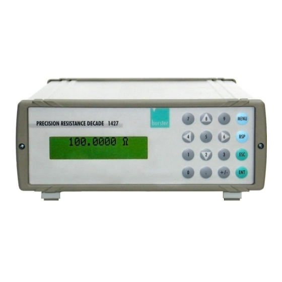
Page 11: Keyboard
Keyboard Figure 3: The Keyboard and the display are located at the front panel Numerical values may be entered from the numerical part of keyboard. The keys 2, 4, 6 and 8 also have a meaning as display cursor keys. The following keys are located at the keyboard, except from the numerical keys: Meaning MENU... -
Page 12: Display
Display Figure 4: The two row display of 1427 The two-row alphanumerical display is located at the front panel of the decade. It is used to display all information. Main values, e.g. simulated temperatures or output resistances, are displayed in the upper row. -
Page 13: Preparation For Use
The voltage supply has to be in the range from 100 V to 240 V, the frequency in range from 47 to 63 Hz. The 1427 decade is a laboratory device. Its accuracy is valid at a temperature of 23 °C ± 5 °C. -
Page 14: Operation
Operation Standard mode After switching on the decade operates in the standard mode. The following information is shown at the display: The upper row shows the simulated temperature in “°C” or the generated resistance in “Ω”. The lower row shows the type of the simulated temperature sensor (Pt100) and the setup temperature scale IPTS68 or ITS90 according to the IEC751 standard or US according to the US/JIS standard. -
Page 15: Numerical Keyboard
5.1.2 Numerical keyboard With the numerical keys temperature or resistance values may be entered directly. A recently entered value is displayed in brackets under the active value. To confirm the new value: Push the ENT key. Pushing the ENT key switches the keys 2, 4, 6 and 8 to cursor mode. To delete the last entered number: Push the BSP key. -
Page 16: Function
5.2.1 Function Push the MENU key at standard mode. Call up the “Function” parameter with cursor key ▲ or ▼. Set the decade to the desired mode. To do this, use the cursor keys ◄ and ►. The available modes are shown at the following. -
Page 17: R , The Resistance At 0 °C (Pt, Ni)
R(T) = 330*exp (-4050*((1/298.15)-(1/(T+273.15)))) is preset. The range of simulation is –30 °C to 110 °C. Short (Version 1427-Vx1x) Simulates “Short” at the output terminals. The function “Short” is an extra ordered option. Open (Version 1427-Vx1x) Simulates “Open” on the output terminals. The function “Open” is an extra ordered option. -
Page 18: 2W (The Highest Resistance Value On R4W Terminals)
5.2.3 4W<2W (the highest resistance value on R4W terminals Use this function to define the resistance value, for the switch over of the active output terminals from R4W to R2W and back automatically. Resistance values higher than 10 000 Ω are only available on terminals R2W. Lower values than 10 000 Ω... -
Page 19: Click Volume (Volume)
5.2.5 Click Volume (Volume) Press the “MENU” key at standard mode. Select the Parameter “Volume” with the cursor keys ▲ and ▼. Select the desired volume with the keys ◄ and ►. You may set the volume incremental. There are 15 increments of volume. “00” means no click when a key is pressed and “15”... -
Page 20: Lightning
To set the address off an IEEE488 decade (IEC addr): If the decade is equipped with an optional IEEE488 Interface, you may set the IEEE488 address of instruments instead of the “Baud rate”. The address range is “0” to “30”. 5.2.7 Lightning Using this parameter you may enable or disable the display lightning. -
Page 21: Calibration Mode Password Setting (Cal. Code)
5.2.8 Calibration mode password setting (Cal. code) To access the calibration mode you have to enter a five digit password. If the password is set to “00000”, this information is displayed in the setup menu. Otherwise the decade displays “*****”. Note: Write down the active password. -
Page 22: Serial Number (Serial N.)
5.2.9 Serial number (Serial n.) Displays the serial number of the decade. To display the serial number: Press the “MENU” key at standard mode. Select the Parameter “Serial n.” with the cursor keys ▲ and ▼. The display now shows the serial number. Note: This parameter cannot be changed. -
Page 23: Calibration Mode
Calibration mode In this mode you may recalibrate the resistance elements of the decade. To get access to the calibration mode: Press twice the “MENU” key at standard mode. At SETUP mode you have to press this key only at one time. Before calibration you have to enter the correct password. - Page 24 Standard (terminals) Nominal value Requested Accuracy R11 (R4W) 3480 Ω 100 mΩ R12 (R4W) 6870 Ω 250 mΩ R13 (R4W) 13.5 kΩ 500 mΩ R14 (R4W) 26.6 kΩ 1 Ω R15 (R4W) 52.2 kΩ 5 Ω R16 (R4W) 103 kΩ 10 Ω...
-
Page 25: Recommended Connection Of Standard Ohm-Meter
5.3.1 Recommended connection of standard ohm-meter Terminals R4W for calibration points R00 to R26: Terminals R2W for calibration points R27 to R35: Page 25... -
Page 26: Calibrating
5.3.2 Calibrating Set the first calibration point (resistance element). Use the keys ▲ and ▼ to set the element. Measure the resistance of the selected element. Use a ohm-meter with appropriate accuracy in 4 and 2-wire wire connection. Switch the keypad to numerical mode. -
Page 27: Performance Verification Test
Performance verification test The verification procedure is based on the measuring of the resistance at the decade output terminals with a standard multimeter in recommended points. Required equippment You need an ohmmeter with a nominal accuracy of 0.001 % in range 1 Ω to 1.2 MΩ (e.g. Wavetek 1281, FLUKE 8508 or similar). - Page 28 Table 2: Maximum deviations (R4W) Nominal value [Ω] Max. deviation [mΩ] 1.00000 3.03 2.00000 3.06 5.00000 3.15 10.00000 20.0000 50.000 100.000 200.00 500.00 1000.0 2000.0 5000.0 10000.0 1500 Connect the standard ohm-meter to the R2W terminals of the resistance decade. ...
- Page 29 Table 3: Maximum deviations (R2W) Nominal value [Ω] Max. deviation [Ω] 1.00000 0.01 10.00000 0.011 100.000 0.015 1000.0 0.060 2000.0 5000.0 0.25 10000.0 20000.0 50000 100000 200000 500000 1000000 1200000 Page 29...
-
Page 30: Remote Control
For data flow control neither hardware handshake (RTS/CTS) nor program handshake (XON/XOFF) is used. The RS232 line is metallically separated to other electronic circuits. RS232 connection Figure 5: 9 pin connector D-SUB FEMALE (view to the 1427’s rear panel) Label Description output... -
Page 31: Remote Control Ieee488 (Optionally)
Go To Local - disables the remote control “LLO” Local Lock Out - disables the local control, the 1427 can only be controlled by remote control. Other commands are identical to the RS232 interface commands. You’ll find a detailed description at chapter 7.3 “Commands”... -
Page 32: Commands
A command is always a letter followed by a parameter and ended by control sign <cr> or <lf>. The response is always ended with the control signs “<cr><lf>”. If an unknown command is received the 1427 returns the string "? <cr><lf>“. A correct executed command is confirmed by the string "Ok <cr><lf>. -
Page 33: Command List
In case of a command, the decade confirms the correct setting with the string „Ok <cr><lf>”. In case of a query, the 1427 returns the set resistance/temperature value in the same format as it is set for the display (number of decimal places). -
Page 34: Decade Function Setting
Ni temperature sensor simulation Custom temperature sensor simulation Short simulation (extra ordered option) Open simulation (extra ordered option) The 1427 confirms the execution with the string „Ok <cr><lf>”. Example: „F1<cr>” sets the simulation of a Pt100 sensor (temperature scale IPTS68). 7.4.3... -
Page 35: R Setting / Reading
Ω. The limits are shown in chapter 9 “Specifications”. The 1427 confirms the execution with the string „Ok <cr><lf>”. In case of a query the 1427 returns the set value in Ω. Example: „R100 <cr>” sets the value R to 100 Ω... -
Page 36: Status Reading
7.4.6 Status reading 1427 returns the device status in the form „FxUx <cr><lf>“. The values corresponding to the actual status of decade are located at the positions of the „x“ signs (refer to chapter 7.4.2: “Decade function setting” and chapter 7.4.5: “Temperature unit setting (T.unit)”. -
Page 37: Demo Program
Demo program To provide an easy operation of the instrument from the computer, and to check the RS232 line (IEEE488 bus) of the instrument, a simple operating program is delivered with the decade. The installation disk contains a program (for WIN95/98/ME/NT/2000/XP/WIN7/WIN8 only), that allows your computer to communicate with the instrument through a standard serial line (IEEE488). -
Page 38: Program Description
Program description When launching the program “R decade”, the following control panel is displayed on your screen. Figure 7: R Decade First select the appropriate interface (RS232 or IEEE488). To select the interface use the operating element „Communication“. Standard is RS232. To control the decade with the RS232 Interface. -
Page 39: Specifications
Only values, functions, ranges with signed accuracy in relative or absolute expression or where limits are specified, are guaranteed. Resistance range 1.000 00 Ω - 1 200 000 Ω SHORT, OPEN terminals (version 1427-Vx1xx only) Pt sensor temperature simulation -200.000 °C to 850.000 °C (-328 °F to 1562 °F) Ni sensor temperature simulation -60.000 °C to 300.000 °C (-76 °F to 572 °F) - Page 40 Safety class I according EN61010 Uses external fuses T 1.0 A Uses internal fuses T 2.0 AH Reference temperature +18 °C … +28 °C Working temperature +5 °C … +40 °C Storing temperature -10 °C … +50 °C Housing ALU (aluminium) Dimensions (table version) Width: 250 mm Height: 100 mm...
-
Page 41: Accuracy
Accuracy Specified accuracy is valid after a 10 minute warm up period in temperature of 23 ± 5 °C. Uncertainties include long-term stability, temperature coefficient, linearity, load and line regulation and traceability of factory to national calibration standards. Accuracies are assigned in % of the set value. The Specified accuracy is valid for one-year. - Page 42 Short and Open simulation (version 1427-VX1X only) When the SHORT function is selected, the output resistance is lower than 100 mΩ (typically 50 mΩ). The maximum allowed current is 500 mA. When OPEN function is selected, the output resistance is higher than 1 GΩ. The maximum allowed voltage is 50 V eff.
-
Page 43: Disposal
Disposal Battery disposal In Germany, the end user is legally obliged to return all used batteries, and it is illegal to dispose of batteries in the household waste. This law may also affect you as purchaser of the instrument described here. Please dispose of your used batteries properly and in accordance with national statutory regulations.
Need help?
Do you have a question about the 1427 and is the answer not in the manual?
Questions and answers