
Subscribe to Our Youtube Channel
Related Manuals for Rinnai SS850


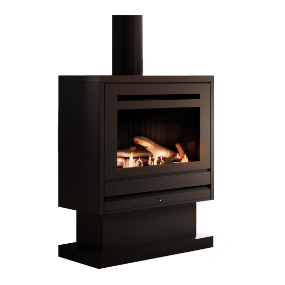
Summary of Contents for Rinnai SS850
- Page 1 MODELS: RINNAI SS850 (SS850ICAN) NG RINNAI SS850 (SS850ICAL) LPG RINNAI SS850 (SS850CLN) NG RINNAI SS850 (SS850ICLL) LPG Gas Fireplace Installation Manual...
- Page 2 Congratulations on the purchase of your Rinnai SS850 Gas Fire. We trust you will have many years of comfort and enjoyment from your appliance. BEFORE INSTALLING THIS APPLIANCE Before proceeding with the installation read this manual thoroughly and gain a full understanding IMPORTANT of the appliance, to ensure safe and correct use.
-
Page 3: Table Of Contents
Wiring Diagram .................................. 36 Contacts This appliance MUST be installed, maintained and removed ONLY by an Authorised Person. For continued safety of this appliance it MUST be installed and maintained in accordance with WARNING the manufacturers instructions. Rinnai SS850 IM... -
Page 4: Warnings & Important Information
For safety and warranty purposes, appliances that may be damaged or incorrect MUST NOT be installed or operated under ANY circumstances. Installation of damaged or incorrect appliances may contravene local government regulations. Rinnai disclaims any liability or responsibility whatsoever in relation to the installation or operation of damaged or incorrect appliances. -
Page 5: Modifications
Flue terminal MUST always vent directly to outdoors. DO NOT extend the flue vertically or horizontally in ways other than prescribed in this appliance manufacturer’s installation instructions. ONLY the flue components specified by Rinnai MUST be used. When considering installation ensure minimum clearances as follows are adhered to. -
Page 6: Before You Start
Please keep these instructions in a safe place for future reference. CARTON CONTENTS / ITEM CHECKLIST The following table lists the components for the Rinnai SS850 Gas Fires. Ensure that all the relevant components for the model being installed are present before proceeding. -
Page 7: General Installation Information
They are allowed providing they are outside the minimum clearances shown. The SS850 gas fireplace is not designed to be built into bookcases. Mantel needs to be a min. of 400 mm away from the edge of the glass Max. -
Page 8: Flooring And Hearth Material Selection
For a 200mm deep non-combustible hearth, the calculation for hearth height would be: 450mm - hearth depth (A) (450mm - 200mm = 250mm). The non-combustible hearth height would need to be 250mm minimum. This would mean the floating hearth dimensions could be 200mm deep and 250mm high. Rinnai SS850 IM... -
Page 9: Tv Installation
GENERAL INSTALLATION INFORMATION TV INSTALLATION The SS850 has a fan that distributes warm air from the top of the appliance out into the room. As warm air is dispersed outwards and not directly upwards, installation of a TV may be an option. -
Page 10: Framing
* When preparing the cavity the minimum depth must be inclusive of the external cladding thickness for false fireplace installations. It is the installers responsibility that adequate clearance be provided between the heater engine and electrical connections. CAUTION ‡ Corner installations use False Fireplace enclosure dimensions and framing specifications. Rinnai SS850 IM... -
Page 11: Supply Connections
Consumer piping to be terminated 230 mm from the front of enclosure. ④ Masonry fireplace installations: Gas supply dimension MUST include the thickness of infill panel (when fitted). IMPORTANT A standard Rinnai infill panel adds 2mm to the front of the enclosure. ④ False fireplace installations: Gas supply dimension MUST include thickness of the cladding used. -
Page 12: Electrical Supply
Remove the pre-punched metal knock-out located in the lower left or right edge of the frame, ensuring the grommet is fitted to the metal knock-out. Excess cord may be left in the cavity below the unit—DO NOT coil excess cord. Rinnai SS850 IM... -
Page 13: Flueing
Supporting the flue is usually completed during the framing stage with flue supports or straps within the cavity. Wall straps have been included in the Rinnai coaxial vertical flue kit. Elbow straps are also available as a separate component to prevent excess weight on the flue elbow (if used). -
Page 14: Flueing Option: Masonry
If located in a windy areas, then a DV high wind vertical cowl protection kit (RDB992) is recommended. It is designed to wrap around the vertical flue cowl to reduce wind entering the flue and causing flame disturbances. Refer page 17 for more information. Rinnai SS850 IM... -
Page 15: Flueing Option: False Fireplace
If located in a windy areas, then a DV high wind vertical cowl protection kit (RDB992) is recommended. It is designed to wrap around the vertical flue cowl to reduce wind entering the flue and causing flame disturbances. Refer page 17 for more information. Rinnai SS850 IM... -
Page 16: Flue Components
Outer: Galvanised steel (Ø170 mm) 230 mm RDV907 300 mm RDV906 Coaxial vertical flue 600 mm RDV904 cowl 900 mm RDV903 RDV991 1200 mm RDV902 Aluminium flue terminal required coaxial vertical flue installations— part of vertical flue kit. Ø268 mm Rinnai SS850 IM... - Page 17 230 mm RDV907 257 mm 473 mm 300 mm RDV906 311 mm 527 mm 600 mm RDV904 524 mm 740 mm Rise 900 mm RDV903 737 mm 953 mm 1200 mm RDV902 949 mm 1165 mm Offset Rinnai SS850 IM...
-
Page 18: Flue Installation Dimensions & Restrictions Flue Terminal Clearances
A flue terminal is considered to be a source of ignition. For appliances not addressed above acceptance should be obtained from the Technical Regulator. FIGURE 6.2 (in-part) MINIMUM CLEARANCES REQUIRED FOR FAN-ASSISTED FLUE TERMINALS, ROOM-SEALED APPLIANCE TERMINALS AND OPENINGS OF OUTDOOR APPLIANCES Rinnai SS850 IM... -
Page 19: Installation
INSTALLATION FALSE FIREPLACE INSTALLATION When installing the Rinnai SS850 into a purpose built false fireplace, which is not open to the roof space of the building, cavity vents will need to be added. IMPORTANT Heat lost through the outer skin of the appliance and flue system may not adequately vent. This can lead to excess heat in the cavity. - Page 20 INSTALLATION False Fireplace Installation Overview: False Fireplace enclosure SS850 with Zero Clearance Box and adapter removed Zero Clearance Box installed Zero Clearance Box and coaxial flue adapter Zero clearance box Coaxial flue adapter Aeration plate Red exhaust seal Rinnai SS850 IM...
-
Page 21: Masonry Installation
10. Complete gas connection 11. Install the burn media and commission Install the burn media, refer page 25. Refit the glass and the inner and outer frames. If using an infill panel, refer separate instructions. Rinnai SS850 IM... - Page 22 Actual chimney size needs to be at least 200 x 200 mm for the two flexi flues to fit Masonry adapter frame Exhaust flue Colinear Air intake flue adapter Aeration plate Green air inlet seal Red exhaust seal Rinnai SS850 IM...
-
Page 23: Aeration Plates
INSTALLATION AERATION PLATES The SS850 comes with two aeration plates that are factory fitted, in a position for flues between 3-5.5 m, refer image below. There are a further two aeration plates supplied in the accessory pack (for flues 5.6-8 m). -
Page 24: Fire To Flange Connection
It is critical to ensure that the air and flue seals are correctly compressed. If there is a gap present, there may not be a proper seal and performance could be affected. Fixing check markers Rinnai SS850 IM... -
Page 25: Burner Media Installation
The appliance MUST NEVER be used with other burn media or burn media that is damaged. Ensure the left hand log is sitting on top of the two support brackets and NOT directly on the burner. Ensure the left hand log is pushed hard against the left and rear ceramic panels. Rinnai SS850 IM... - Page 26 You will have granules left over. DO NOT place the granules directly in front of the pilot flame If there are some abnormally long streaky flames, then readjust the granule position around the burner holes until the flames have improved. Rinnai SS850 IM...
-
Page 27: Commissioning
The location of the gas control is in the air gap at the lower right hand side of the appliance. The location of the data plate is on the base plate of the heater engine within the air gap on the right hand side of the appliance. Rinnai SS850 IM... - Page 28 Check the pressures as per the chart below for the correct gas type. Ensure all other gas appliances in the household are running on 'High' Press the heater ON/OFF button to stop the appliance operation. Disconnect the manometer hose and replace the inlet test point screw . Check for leaks using soapy water solution. Rinnai SS850 IM...
- Page 29 Always check gas pressure values to those recorded on this appliances data plate, values on the data plate override values printed in this instruction. WARNING Rinnai SS850 IM...
-
Page 30: Commissioning The Appliance For Different Gas Type
With the appliance OFF, press the 'TEST' button, the gas type code will be shown on the display. Press the 'SET' button, to lock in the code. Gas pressure settings should now be checked as per "Step 7. Checking and setting Pilot burner pressure" on page 29, point 1 through 3. Rinnai SS850 IM... -
Page 31: Attaching Fascia Assembly
The glass of the fascia fitted to this appliance reduces the risk of fire and injury and no part of it should be permanently removed. NOTE For protection of young children or the infirm a secondary guard is required. Rinnai SS850 IM... -
Page 32: Abnormal Flame Pattern
COMMISSIONING ABNORMAL FLAME PATTERN Each Rinnai Gas Fire has a distinct flame pattern. The flame should look the same every time you start your heater, after an initial warm up period of approximately 15 minutes. Abnormal flame performance and/or pattern can indicate a problem with your heater, such as blocked gas injectors, incorrectly installed / inadequate flue system or the Ceramic logs / stones and or burner media may have shifted from when the heater was first installed. -
Page 33: Installation Checklist
Is the appliance positioned in a suitable location (clearances, combustible clearances, mantels and surrounds etc.)? 2. Was a Rinnai approved flue system installed and tested in accordance with the instructions? 3. Has the gas pressure been checked and set with all gas appliances running? 4. -
Page 34: Specifications
BE installed with a Rinnai flue System. Flueing - False Chimney Co-linear (air intake Ø75mm, exhaust Ø100mm) to Coaxial direct vent flueing (inner Ø100mm, outer Ø170mm). Appliance must be installed with a Rinnai flue System. Convection Fan 120V AC 50 Hz-2-speed centrifugal blower Gas Connection Brass 1/2”... -
Page 35: Dimensions
SPECIFICATIONS DIMENSIONS Coaxial in Timber Colinear in Masonry Viewable glass Viewable glass 533 x 295 533 x 295 26.5 1050 Masonry infill panel Rinnai SS850 IM... -
Page 36: Wiring Diagram
4 3 2 1 3 2 1 w w bk bk bl r OH.TH1 R.TH bl w FR2 FR1 SV 3 SV 2 SV 1 ON/OFF DISPLAY UNIT CONTROL DISPLAY UNIT WIRING DIAGRAM UNI CONTROL RIB23, RDV23 Issue A Rinnai SS850 IM... - Page 37 NOTES Rinnai SS850 IM...
- Page 38 NOTES Rinnai SS850 IM...
- Page 39 NOTES Rinnai SS850 IM...
-
Page 40: Contacts
13749 SS850 Installation Manual - Issue 2 - JULY 2022...
Need help?
Do you have a question about the SS850 and is the answer not in the manual?
Questions and answers