Table of Contents
Advertisement
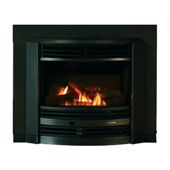
Electronic Timer and Remote
Operating and Installation Instructions
Timberflame IB35 ETR - New Zealand
IMPORTANT
This appliance shall be installed in accordance with:
Manufacturers Installation Instructions.
•
Local Gas fitting regulations.
•
Municipal Building codes.
•
AGA Gas Installation Code AG601 - NZ 5261.
•
Any other relevant statutory regulation.
•
Rinnai strongly recommend that this product be installed with an
•
appproved flue system for optimum product performance.
This appliance must only be installed, serviced and removed by an
•
authorised person.
Flame Fire ETR
Table of Contents
Customer Instructions
Installation Instructions
Installation Checklist
Installer Details
3
4
6
7
8
9
10
11
12
14
15
17
17
18
20
20
Advertisement
Table of Contents

Related Manuals for Rinnai Timberflame IB35 ETR


Summary of Contents for Rinnai Timberflame IB35 ETR
-
Page 1: Table Of Contents
AGA Gas Installation Code AG601 - NZ 5261. • Any other relevant statutory regulation. • Rinnai strongly recommend that this product be installed with an • appproved flue system for optimum product performance. This appliance must only be installed, serviced and removed by an •... -
Page 2: Control Panel Layout
CONTROL PANEL LAYOUT TIME/TEMP. Display LOCK Button Shows either the time of day, Indicates lock temperatures or coded error function messages. CLOCK ADJUSTMENT AND TIMER INDICATORS Indicates that clock or dual timer programme is being set. Flame Function Med. High heat setting and overides thermostat TIMER Indicator TIME / TEMP. -
Page 3: Operation
OPERATION TO OPEN THE CONTROL PANEL • Lift lightly in the centre of the lid where there is a catch. The control panel lid will then open backward to an angle. TURNING ON • Press the ON/OFF button to operate the heater. The ON indicator will glow green. The spark generator will be heard before the burner ignites and the ON indicator glows red, indicating that the burner is alight. -
Page 4: Remote Control
OVERRIDE • This function is intended to be used to manually override the current operation of the heater. For example; If the heater is in standby mode (ie. between finishing time and starting time of a Timer), and the OVERRIDE button is selected, then the heater will begin to operate and heat the room. To operate the OVERRIDE simply press the OVERRIDE button. -
Page 5: Setting The Clock
SETTING THE CLOCK SETTING THE CLOCK • --:-- When the appliance is first plugged in or after a power failure, the Digital Display will show As an example, let’s set the clock to 10:35 am: Press the SET TIMES button once, the Clock indicator will flash. Press and hold the “... -
Page 6: Operating The Timers
OPERATING THE TIMERS OPERATING THE TIMERS • Before operating the Timer(s), the clock time must be correct and a starting time and finishing time for the Timer(s) must be programmed. See page 5. The two Timers operate in the same way. This heater does not commence operation at the programmed starting time. -
Page 7: Error Codes
ERROR CODES ERROR CODE MESSAGE • The Flame Fire ETR has the ability to check its own operation continuously. If a fault occurs, an Error Message will flash on the Digital Display of the control panel. This assists with diagnosing the fault, and may enable you to overcome a problem without a service call. -
Page 8: Safety Points
SAFETY POINTS Do not restrict the warm air discharge by This appliance must not be used for any pur- placing articles in front of the heater. pose other than heating. Do not spray aerosols whilst the heater is Young children should be supervised at operating. -
Page 9: Troubleshooting
Ensure appliance fan switch is in ON position Normal operation Small soot deposit No action required Severe soot deposit Inadequate Flue System Call Rinnai Service Dept./Agent forming on Glass or Log Misalignment Logs Incorrect Gas Pressure Condensation on Glass Normal operation... -
Page 10: Location
8. The heater must be mounted on a hearth no less than 50mm. high and the width and depth of the heater. 9. Under no circumstances must combustible materials be present on the inside of the fireplace recess or flueway. For combustible opening installations, a Rinnai Zero Clearance Kit is available from your gas appliance retailer. -
Page 11: Flueing
There must be no leakage of smoke through the structure of the chimney during or after the test. Inside, upstairs and/or adjacent rooms should also be checked. If any of the above criteria is not met, a Rinnai approved flue liner system must be installed. -
Page 12: Chimney Inspection
CHECK DIMENSIONS OF FIREPLACE • Check dimensions of fireplace and if necessary bring them to dimensions shown. CHECK FLUEWAY • Check flueway is clear of obstructions. Provide a firm, flat and sealed base for unit. Sealed means no holes or openings in fireplace. A rough base may affect the performance of this unit CHIMNEY INSPECTION A. -
Page 13: Gas Connection
GAS CONNECTION RUN GAS SUPPLY • For pipe sizing, refer to your local gas installation codes. Copper supply should be run leaving the end of the pipe in a suitable position to be able to attach to the stainless steel flexi- tube and the 1/2”... -
Page 14: Log Installation
LOG INSTALLATION he logset is packed inside the heater and the packaging must be removed prior to installing the logset in its correct position. • Open both side panels. • Remove fastenings on both sides of the top glass retainer. Lift retainer away from heater. -
Page 15: Testing & Commissioning
INSTRUCT CUSTOMER ON USE OF UNIT • Explain to customer about use and care of unit. Make sure the customer understands the instructions. EXPLAIN • Ignition, Adjusting heat level, Fan Switch, Turning “OFF”. NOTE: RINNAI RESERVES THE RIGHT TO CHANGE OR MODIFY SPECIFICATIONS WITHOUT NOTICE. -
Page 16: Technical Data
Comple Model: IB35ETRN (NG) New Zealand IB35ETRL (Propane) New Zealand Description: Rinnai Inbuilt Radiant/Convector, glass-fronted, ceramic log space heater with forced convection and natural draught flue system. Input: 33 MJ/h Natural Gas and Propane. Gas Control: Rinnai Electronic Control Valve. -
Page 17: Wiring Diagram
WIRING DIAGRAM... - Page 18 INSTALLATION / COMMISSIONING CHECKLIST (To be completed by certified Gas Installer) ____________________ Model: 1. Was a fireplace inspection carried out? (ie. clearances, combustibles etc.) 2. Was chimney inspected? 3. Did chimney require flue liner system to be installed? If NO, did chimney meet specified criteria as per manual? 4.
Need help?
Do you have a question about the Timberflame IB35 ETR and is the answer not in the manual?
Questions and answers