Extron electronics DMP 64 Setup Manual
Digital matrix processor
Hide thumbs
Also See for DMP 64:
- User manual (152 pages) ,
- Setup manual (2 pages) ,
- User manual (146 pages)
Advertisement
Quick Links
Download this manual
See also:
User Manual
This guide provides basic instructions for an experienced technician to install the DMP 64 ProDSP
Where possible in the following pages, line drawings and photos from an actual installation are used to clarify steps
discussed in the text. Where appropriate, images have one or more numbers corresponding to a specific step described.
Chapter number and titles reference the DMP 64 User's Manual found at
Step 1 — Disconnect power
Disconnect power to the DMP 64 and turn off all devices that will be connected to it.
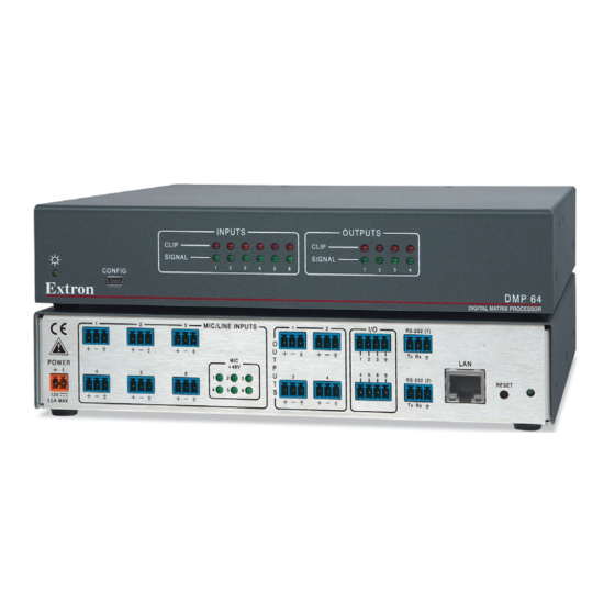
Step 2 — Mount the DMP 64
The DMP 64 is housed in a 1/2 rack width, 9.5" deep, 1U high metal enclosure. Select a suitable mounting location,
then choose an appropriate mounting option. See Chapter 2, "Installation", for additional information.
Step 3 — Cable the Digital Matrix Processor
Run all audio, communication and power cables for operation to the rear panel.
1
POWER
4
12V
1.5A MAX
h
Step 4 — Connect the Mic/Line inputs
Attach up to 6 mic or mono line level devices, balanced or unbalanced, to
the DMP 64 using the wiring diagram to the right.
Step 5 — Connect the audio outputs
For balanced or unbalanced mono audio output, connect an audio output
device to each of the four outputs. Use the wiring diagram to the right.
Step 6 — Connect the I/O ports
To control or monitor external devices, connect up to 6 digital I/O ports. See
Chapter 3, "Rear Panel Operation" and Chapter 5, "Digital I/O Ports" for
additional information.
Step 7 — Connect a control system
Extron recommends using the LAN port for configuration and remote
control of the DMP 64. However there are three options; RS-232,
USB and LAN. See Chapter 2, "Rear Panel Features and Cabling"
for additional information.
RS-232 — Connect the host RS-232 cable to the 3-pin captive screw
connector on the rear of the switcher.
USB — Connect the host USB port to the front configuration port
using a USB to mini-USB cable.
LAN — Using a standard ethernet cable, connect to the network via
the LAN port (
). To connect the DMP 64 directly to a computer,
i
use a crossover ethernet cable. The table at right shows the default
network settings.
DMP 64 Setup Guide
3
MIC/LINE INPUTS
2
O
U
T
MIC
P
+ 48V
U
5
6
1
2
3
T
6
S
4
5
d
www.extron.com.
1
2
I/O
RS-232(1)
Tx Rx
1 2 3
4 5 6
3
4
RS-232(2)
Tx Rx
e
f g g
Tip
Sleeve
Do not tin
the wires!
IP Address: 192.168.254.254
Subnet Mask: 255.255.0.0
Default Gateway: 0.0.0.0
™
Digital Matrix Processor.
DMP 64
LAN
RESET
Tip
Ring
Sleeve
Unbalanced
Do not tin the wires!
Digital I/O Wiring
RS-232
Device
Bidirectional
Transmit (Tx)
Transmit (Tx)
Receive (Rx)
Receive (Rx)
Ground (
)
Ground (
68-1790-50 Rev. A
DHCP: OFF
Balanced
1
2
3
_
Tx
Rx
)
10 09
Advertisement

Related Manuals for Extron electronics DMP 64


Summary of Contents for Extron electronics DMP 64
- Page 1 Step 2 — Mount the DMP 64 The DMP 64 is housed in a 1/2 rack width, 9.5" deep, 1U high metal enclosure. Select a suitable mounting location, then choose an appropriate mounting option. See Chapter 2, "Installation", for additional information.
- Page 2 2. For the User's Manual, select the Manuals tab, then select the DMP 64 User's Manual from the list of available documentation. The manual, in PDF format, will open in the browser window or can be downloaded to the hard drive for future reference.
Need help?
Do you have a question about the DMP 64 and is the answer not in the manual?
Questions and answers