
Related Manuals for Kärcher HD 6/15 M


Summary of Contents for Kärcher HD 6/15 M
- Page 1 HD 6/15, HD 7/17 (M/MX) HD 7/14-4, HD 7/16-4, HD 8/18-4 (M/MX) with HD-M Cage variants 5.906-780.0 (05/18)
-
Page 2: Table Of Contents
11.4.19Removing/installing the swash plate for 4-pole mo- HD 6/15 M/MX cross-section drawings..tors ........ -
Page 3: Foreword
2 pieces for three-phase devices No pressure regulation via servo control (single-phase Annealed rotor for good motor startup (HD 6/15 M) devices). Pressure regulation via a separate power con- Aluminium winding package (HD 6/15 M) trol spray lance ... -
Page 4: Intended Use
Cable clips Accessories possible Rotary nozzle Rubber strap as transport lock for mains cable and high- Foam lance pressure hose (not with CX variant) Power Control spray lance Additional spray lance holder with a clamp for transport ... - Page 5 Foam nozzle Bottle Driving nozzle Detergent injector nozzle Suction hose Air injector nozzle Gate sieve The foam lance is used for adding detergent when per- forming high pressure cleaning. The water flow through the driving nozzle and detergent in- jector nozzle generates a vacuum that sucks detergent out of the bottle.
-
Page 6: Overview Of The Unit
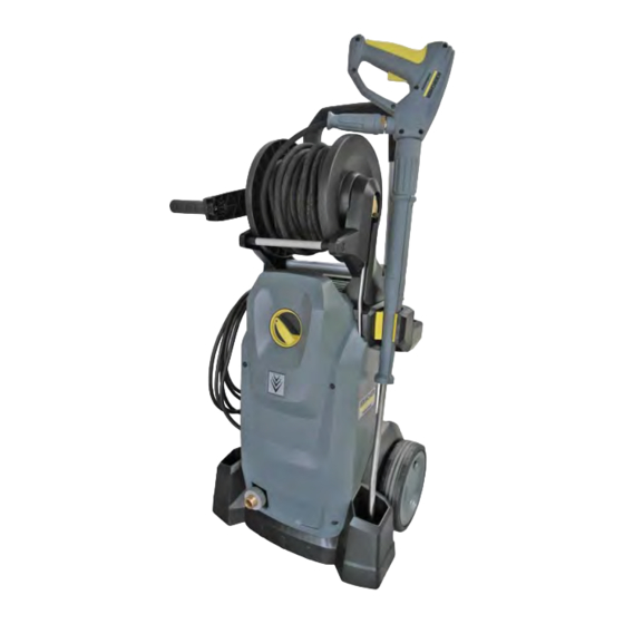
Overview of the unit Water connection Shoulder module with spray lance holder Pump set Type plate Rotary knob High-pressure outlet (Standard variant) Power supply cable Hose reel (X variants only) Handle Trigger spray gun Pipelines (X variants only) English... -
Page 7: Overview Of Electrical Box Hd 6/15 Mx
HD-M Cage variant Overview of electrical box HD 6/15 MX Power supply cable Capacitor Motor circuit breaker reset bow Motor circuit breaker Actuator Power switch English... -
Page 8: Overview Of Electrical Box Hd 8/18 M
Overview of electrical box HD 8/18 M Power supply cable Circuit breaker Motor circuit breaker reset bow Motor circuit breaker Actuator Power switch Pump head HD 6/15 MX overview Suction valves Suction bridge Water inlet Startup valve Pressure relief valve Pressure switch High-pressure outlet Pressure retention valve... -
Page 9: Hd 6/15 M/Mx Cross-Section Drawings
HD 6/15 M/MX cross-section drawings Cylinder head Suction/pressure valve Plate Plugs Pressure relief valve Retaining plate Cylinder head Caps Plugs Pressure retention valve Water inlet with filter Sleeve Suction bridge Sleeves Sleeve English... -
Page 10: Pressure Relief
Startup valve Spring Valve seat Ball Sleeve Startup valve Note Replacement startup valve only as a complete unit. The startup valve eases the motor startup in single-phase devic- The spring holds the ball open when the device is switched off. The motor starts up without back-pressure. - Page 11 HD 6/15 M/MX pump set Radial shaft seal Low pressure seal Ball bearing (A bearing) Washer (brass) Swash plate Socket Axial bearing O-ring Piston High pressure seal Piston guide Gasket package Washer (plastic) English...
-
Page 12: Straight Thrust Guide
Straight thrust guide Washer Piston spring Piston Oil groove ring Piston guide Motor Casing Ball bearing (B bearing) Rotor Radial shaft seal Winding Ball bearing (A bearing) Air guide Motor shaft English... -
Page 13: Hd 8/18 M Cross-Section Drawings
HD 8/18 M cross-section drawings Cylinder head Suction bridge Pressure retention valve Screws Overflow valve Suction/pressure valve Pressure relief valve Valve screws Water inlet with filter English... - Page 14 Overflow valve Replacement complete pressure limiter and valve servo Spring only available as a complete spare parts kit. Taper The overflow valve is used for pressure regulation and pro- Valve seat vide overpressure protection. Sleeve The pressure in the system rises or falls according to the Piston setting of the rotary control on the gun.
-
Page 15: Swash Plate
Pressure relief valve Pressure relief valve Valve screw After the device is switched off, the pressure relief valve lowers the device pressure to approx. 50 bar via the gun. This preserves the pipeline system and eases opening of the gun. When the gun is closed, the pressure tip briefly opens the return line to the suction chamber, thus reducing the device pressure. - Page 16 Motor HD 8/18 M Casing Ball bearing (B bearing) Rotor Radial shaft seal Winding Tapered ball bearing (A bearing) Air guide Motor shaft English...
-
Page 17: Hd 7/17 M Cross-Section Drawings
HD 7/17 M cross-section drawings Pump set Radial shaft seal Axial bearing Ball bearing (A bearing) Piston Swash plate Piston guide English... -
Page 18: Structure Of Service Group
Structure of service group 010 Safety instructions DANGER CAUTION Danger of lethal electric shock from electrical voltage. Risk of injury from escaping high-pressure water. Switch off the device immediately and unplug the mains Depressurise the system prior to all work. CAUTION plug before performing work. - Page 19 030 Function No special functional features. 040 Service activities Note Unless otherwise described, installation is performed in re- verse order. 9.4.1 Opening / closing the cover Rotary knob Cover Screws 1. Turn the rotary knob to position "0". 2. Unscrew the screws. 3.
- Page 20 9.4.3 Removing/installing the electrical box HD 6/15 MX 9.4.2 Opening / closing the electrical box 10.4.1 Removing/installing the capacitor 10.4.4 Removing/installing the power supply cable 10.4.2 Removing/installing the motor circuit breaker 10.4.6 Removing/installing the power switch Electrical box 1.
- Page 21 9.4.6 Removing/installing the hose reel angle piece 11.4.1 Removing/installing the pipeline HD 6/15 MX Screw Handle High-pressure hose Clip Sleeve and rod Rod screw 1. Unroll the high-pressure hose. 2. Pull out the clip. 3. Pull off the high-pressure hose. 4.
- Page 22 O-ring Screw Retaining ring Series design illustration Replacement design illustration 13.Install the angle piece according to the version. 9.4.7 Removing/installing, disassembling the shoulder module 9.4.9 Removing/installing the hose reel 11.4.15 Removing/installing the pump set (non-cage variants) Screws Shoulder module 1.
- Page 23 9.4.8 Removing/installing a wheel Hubcap Retaining ring Wheel 1. Remove the hubcap. 2. Remove the retaining ring. 3. Remove the wheel. Installation information Use a new retaining ring. 9.4.9 Removing/installing the hose reel Pipeline Clip O-ring Support ring 1. Pull out the clip. 2.
- Page 24 9.4.10 Removing/installing the power switch linkage 9.4.1 Opening / closing the cover Rotary knob Guide Power switch linkage Lever 1. Pull off the rotary knob. 2. Pull the power switch linkage out of the guide. 3. Remove the power switch linkage from the lever. 4.
-
Page 25: Service And Inspection
050 Service and inspection 9.5.1 Cleaning the water filter Water filter O-ring Water connection 1 Unscrew the nuts. 2 Pull out and clean the water connection with water filter. Installation information Check the O-rings for wear and damage and replace if necessary. -
Page 26: Electrical System Service Group
Electrical system service group 10.1 010 Safety instructions DANGER CAUTION Danger of lethal electric shock from electrical voltage. Risk of injury from escaping high-pressure water. Switch off the device immediately and unplug the mains Depressurise the system prior to all work. CAUTION plug before performing work. - Page 27 10.3 030 Function No special functional features. 10.4 040 Service activities Note Unless otherwise described, installation is performed in re- verse order. 10.4.1 Removing/installing the capacitor 9.4.2 Opening / closing the electrical box Capacitor Electric socket plug connections 1. Disconnect electrical socket plug connections. 2.
- Page 28 10.4.4 Removing/installing the power supply cable 9.4.2 Opening / closing the electrical box Electric socket plug connections Strain relief Seal Power supply cable Screw 1. Mark the electric socket plug connections. 2. Disconnect electrical socket plug connections. 3. Unscrew the screw. 4.
-
Page 29: 8Removing/Installing The Motor Hd 6/15 Mx
10.4.7 Removing/installing the contactor HD 8/18 M 9.4.2 Opening / closing the electrical box Electrical power cable Screws Circuit breaker 1. Mark the electrical power cable. 2. Unscrew the screws. 3. Remove the electrical power cable. 4. Remove the contactor. Note Remove the electrical power cables individually from the defective contactor and immediately connect to the new... -
Page 30: 9Removing/Installing The Motor Hd 8/18 M
10.4.9 Removing/installing the motor HD 8/18 M 11.5.1 Draining/replacing the pump oil 11.4.15 Removing/installing the pump set (non-cage variants) 9.4.4 Removing/installing the electrical box HD 8/18 M 11.4.19 Removing/installing the swash plate for 4-pole motors Motor bearing Oil drain hose Screw Oil filler neck with cap... -
Page 31: Pump Service Group
Pump service group 11.1 010 Safety instructions DANGER CAUTION Danger of lethal electric shock from electrical voltage. Risk of injury from escaping high-pressure water. Switch off the device immediately and unplug the mains Depressurise the system prior to all work. CAUTION plug before performing work. - Page 32 11.3 030 Function No special functional features. 11.4 040 Service activities Note Unless otherwise described, installation is performed in re- verse order. 11.4.1 Removing/installing the pipeline HD 6/15 MX 9.4.1 Opening / closing the cover Screws Pipeline O-ring 1. Unscrew the screws. 2.
- Page 33 Seal on pressure switch piston Pump head Screws 3. Unscrew the screws. 4. Pull off the pump head. Installation information Ensure the correct mounting position of the seal on re- installation. On installation, tighten the screws in a diagonal se- quence to the specified tightening torque.
- Page 34 11.4.4 Removing/installing the suction valves HD 6/15 MX 11.4.2 Removing/installing the pump head Suction bridge Screws Plate Seal 1. Unscrew the screws. 2. Remove the plate. 3. Remove the suction bridge. Installation information Check the seal for damage and replace if necessary. Grease the seal before installation.
- Page 35 11.4.5 Removing/installing the suction valves HD 8/18 M 11.4.2 Removing/installing the pump head Suction bridge Screws O-ring 1. Unscrew the screws. 2. Remove the suction bridge. Installation information Check the O-ring for damage and replace if necessary. Grease the O-ring before installation. Item number Silicon grease 6.288-044.0...
-
Page 36: 8Removing/Installing The Pressure Valves Hd 6/15 Mx
11.4.7 Removing/installing the pressure retention valves HD 8/18 M 11.4.2 Removing/installing the pump head Valve screw Pressure retention valve 1. Unscrew the valve screw. 2. Pull out the pressure retention valve with valve pliers. Note See special tool. 13.3 Special tool Installation information Grease the O-ring on the pressure retention valve be- fore installation. -
Page 37: 9Removing/Installing The Pressure Valves Hd 8/18 M
Pressure valves Sleeves 3. Remove the sleeves. 4. Pull out the pressure valves with valve pliers. Note See special tool. 13.3 Special tool Installation information Grease the O-ring on the pressure valves before instal- lation. Item number Silicon grease 6.288-044.0 11.4.9 Removing/installing the pressure valves HD 8/18 M ... -
Page 38: 10Removing/Installing The Pressure Switch
11.4.10Removing/installing the pressure switch Sleeve Pressure switch piston 1. Unscrew the sleeve with pressure switch piston. Installation information Grease the O-rings before installation. Replacement pressure switch only as a complete unit. Item number Silicon grease 6.288-044.0 Teflon grease 6.288-079.0 11.4.11Removing/installing the startup valve HD 6/15 MX Startup valve 1. -
Page 39: 13Removing/Installing The Pressure Relief Valve Hd 8/18 M
11.4.13Removing/installing the pressure relief valve HD 8/18 M Valve screw Pressure relief valve 1. Unscrew the valve screw. 2. Remove the pressure relief valve. Installation information Grease the O-rings before installation. Item number Silicon grease 6.288-044.0 Note Replacement pressure relief valve only as a complete unit. 11.4.14Removing/installing the low pressure seals ... -
Page 40: 16Removing/Installing The Pump Set (Cage Variants)
11.4.16Removing/installing the pump set (cage variants) 9.4.1 Opening / closing the cover 11.4.1 Removing/installing the pipeline HD 6/15 MX Retaining plate Rubber buffer Frame Pump set 1. Lay the device down. 2. Remove the cylinder head. 3. Unscrew the nuts. Installation information 1 On installation, first place the retaining plate on the rub- ber buffers ans screw loosely in place with the nuts. -
Page 41: 17Removing/Installing The Pistons And Oil Seals
11.4.17Removing/installing the pistons and oil seals 11.4.14 Removing/installing the low pressure seals 11.4.15 Removing/installing the pump set (non-cage variants) Auxiliary screws Nuts Screws 1. Fit the auxiliary screws with nuts. M8x90 auxiliary screws for HD 6/15 MX M10x100 auxiliary screws for HD 8/18 M 2. - Page 42 Piston guide Pulling tool Oil seal 6. Remove the oil seals with the pulling tool. Oil seal Installation pin 7. Fit the new oil seal onto the installation pin (individual lip in the groove in the pin). Installation information Wet the new oil seal in water before installation. Remove all traces of oil and grease from the holes.
-
Page 43: 18Removing/Installing The Swash Plate For 2-Pole Motors
11.4.18Removing/installing the swash plate for 2-pole motors 11.5.1 Draining/replacing the pump oil 11.4.15 Removing/installing the pump set (non-cage variants) 11.4.17 Removing/installing the pistons and oil seals Ball bearing Running disc Screwdriver Swash plate Screw 1. Remove the running disc. 2. -
Page 44: 19Removing/Installing The Swash Plate For 4-Pole Motors
11.4.19Removing/installing the swash plate for 4-pole motors 11.5.1 Draining/replacing the pump oil 11.4.15 Removing/installing the pump set (non-cage variants) 11.4.17 Removing/installing the pistons and oil seals Bearing plate Motor casing Tolerance ring Air guide Ball bearing (B bearing) Radial shaft seal Tapered ball bearing (A bearing) Motor shaft... -
Page 45: 21Removing/Installing The Overflow Valve
11.4.21Removing/installing the overflow valve Overflow valve Valve seat Valve taper Spring Spare parts kit Spare parts kit 1. Unscrew the overflow valve. 2. Pull out the valve seat with valve pliers. 3. Remove the valve taper and spring. Note See special tool. 13.3 Special tool Installation information Check the parts for wear and replace if necessary. -
Page 46: Service And Inspection
11.5 050 Service and inspection 11.5.1 Draining/replacing the pump oil 9.4.1 Opening / closing the cover Oil cap Oil drain hose Plugs 1. Lay the device down horizontally. 2. Open the oil cap. 3. Lay out the oil drain hose. 4. -
Page 47: Technical Documentation
Technical documentation Device no. Designation Circuit diagram Spare parts list Operating manual 1.150-930.0 HD 6/15 M *EU 0.089-740.0 5.974-555.0 5.967-396.0 1.150-931.0 HD 6/15 MX Plus *EU 0.089-740.0 5.974-947.0 1.151-930.0 HD 7/17 M *EU 0.089-741.0 5.974-949.0 1.151-931.0 HD 7/17 MX Plus *EU 0.089-741.0... -
Page 48: Torques
13.2 Torques All torques are specified in Nm. HD 6/15 M HD 7/17 M HD 7/14-4 M HD 7/16-4 M HD 8/18-4 M Cylinder head screws 23 - 27 23 - 27 40 - 45 40 - 45 40 - 45... -
Page 49: Special Tool
TR thread M22x1.5 Standard on TR thread M22x1.5 Standard on both sides both sides HD 6/15 M HD 7/17 M Piston (D = 12 mm) Piston (D = 14 mm) Installation pin 5.901-141.0 Installation pin 5.901-124.0 High pressure seal instal- 5.901-181.0... - Page 50 (Adapter 2) hose TR MX devices (Adapter 1) Hose reel adapter 6.391-522.0 Pipeline adapter 4.421-739.3 HD 6/15 M HD 8/18 M Auxiliary screws with 7.304-454.0 Auxiliary screws with 7.304-532.0 continuous M8x100 continuous M10x100 thread...
-
Page 51: Circuit Diagram
13.4 Circuit diagram Please always call up the current circuit diagram in DISIS when working on the device. English... - Page 52 English...
Need help?
Do you have a question about the HD 6/15 M and is the answer not in the manual?
Questions and answers