Advertisement
Quick Links
EN50155
Switch
Q
I
I N D U S T R I A L
uick
nstallation
Introduction
T M
ORing's Transporter
series Ethernet switches are designed for industrial
applications, such as rolling stock, vehicle, and railway applications. TES-
2 5 0 - M 1 2 i s a l i t e - m a n a g e d r e d u n d a n t r i n g E t h e r n e t s w i t c h w i t h
5x10/100Base-T(X) ports which is compliant with EN50155 request. With
completely support of Ethernet redundancy protocol, O-Ring (recovery time <
10ms over 250 units of connection), O-Chain and STP/RSTP (IEEE802.1w/D)
can protect your mission-critical applications from network interruptions or
temporary malfunctions with its fast recovery technologies. It is specifically
designed for the toughest industrial environments.
Ethernet switch use M12 connectors to ensure tight, robust connections, and
guarantee reliable operation against environmental disturbances, such as
vibration and shock.
TES-250-M12
can be managed centralized by a powerful
windows utility — Open-Vision. In addition, the wide operating temperature
o
o
range from -40 C to 70 C can satisfy most of operating environment. The
TES-250-M12 can be easily adopted in almost all kinds of applications and
provides the most rugged solutions for managing your network. Therefore,
the switch is one of the most reliable choices for rolling stock and highly-
managed Ethernet application.
Package Contents
The device is shipped with the following items. If any of these items is missing
or damaged, please contact your customer service representative for
assistance.
Contents
Pictures
TES-250-M12
QIG
Preparation
Before you begin installing the device, make sure you have all of the package
contents available and a PC with Microsoft Internet Explorer 6.0 or later, for
using web-based system management tools.
Safety & Warnings
Elevated Operating Ambient: If installed in a closed environment, make sure
the operating ambient temperature is compatible with the maximum
ambient temperature (Tma) specified by the manufacturer.
Reduced Air Flow: Make sure the amount of air flow required for safe operation
of the equipment is not compromised during installation.
Mechanical Loading: Make sure the mounting of the equipment is not in a
hazardous condition due to uneven mechanical loading.
Circuit Overloading: Consideration should be given to the connection of the
equipment to the supply circuit and the effect that overloading of the circuits
might have on overcurrent protection and supply wiring. Appropriate
consideration of equipment nameplate ratings should be used when addressing
this concern.
Q I G
TES-250-M12
TES-250-M12
TES-250-M12
G
uide
Dimension Unit =mm (Tolerance ±0.5mm)
TES-250-M12
EN50155
40.0
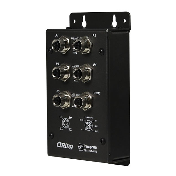
Panel Layouts
Front View
2
Number
P1
P2
1
Ring
1
3
P3
P4
Ring
4
P5
PWR
1
Ring
R.M
5
12-48 VDC
Tx+
Rx+
N.C.
V+
N.C.
V-
N.C.
Rx-
Tx-
TES-250-M12
Installation
Wall-mount
The device can be fixed to the wall. Follow the steps below to install the device on the wall.
Step 1: Hold the
d
evice upright against the wall
Step 2: Insert four screws through the large opening of the keyhole-shaped apertures at the
top and bottom of the unit and fasten the screw to the wall with a screwdriver.
Step 3: Slide the
d
evice downwards and tighten the four screws for added stability.
1907-200-S250M12XX1-FX014
88.9
73.9
44.4
Ø5.0
Ø4.0
Ø8.0
P1
P2
Ring
P3
P4
Ring
P5
PWR
Ring
R.M
12-48 VDC
Tx+
Rx+
N.C.
V+
N.C.
V-
N.C.
Rx-
Tx-
TES-250-M12
1. Fast Ethernet port
1. Reset button
2. LNK/ACT LED for Ethernet ports
3. Ring status LED
4. Power status LED
5. R.M. status LED
6. Power port
6
1
Instead of screwing the screws in all the way, it is advised to
leave a space of about 2mm to allow room for sliding the switch
between the wall and the screws.
PRINTED ON RECYCLED PAPER
EN50155 5-port lite-managed
Ethernet switch
Wiring
For pin assignments of power, console and relay output ports, please refer to the following tables.
Grounding
Grounding and wire routing help limit the effects of noise due to electromagnetic interference
(EMI). Run the ground connection from the grounding pin on the power connector to the grounding
surface prior to connecting devices.
Power port pinouts
The switch provides one set of power supply on a M12 5-pin female A-
coding connector. Insert the power cable to the power connector
on the device and rotate the outer ring of the cable connector
until a snug fit is achieved. Make sure the connection is tight.
Network Connection
The switch has five 10/100Base-T(X) Ethernet ports in the form of M12 connector. Depending
on the link type, the switch uses CAT 3, 4, 5,5e UTP cables to connect to network devices (PCs,
servers, switches, routers, or hubs). Please refer to the following table for cable specifications.
Cable
Type
Max. Length
Connector
10BASE-T
Cat. 3, 4, 5 100-ohm
UTP 100 m (328 ft)
M12 D-coding connector
100BASE-TX
Cat. 5 100-ohm UTP
UTP 100 m (328 ft)
M12 D-coding connector
Pin Definition
10/100Base-T(X) D-coding M12 port
#1
#2
Pin No.
Description
#1
TX+
#4
#3
#2
RX+
#3
TX-
#4
RX-
Configurations
After installing the switch and connecting cables, start the
power. The green power LED should turn on. Please refer to the following tablet
for LED indication.
LED
Color
Status
Description
Green
On
Power is on
Power
Green
On
Device operating in Ring Master mode
R.M
On
O-Ring enabled
Green
Ring
Blinking O-Ring structure is broken
10/100Base-T(X) M12 ports
On
Port is linked
Green
Off
Port is linked-down
LNK/ACT
Blinking Transmitting data
Quick Installation Guide
Version 1.4
N.C.
V+
N.C.
V-
N.C.
d
evice by turning on
Advertisement

Related Manuals for ORiNG TES-250-M12


Summary of Contents for ORiNG TES-250-M12
- Page 1 — Open-Vision. In addition, the wide operating temperature range from -40 C to 70 C can satisfy most of operating environment. The Ring 12-48 VDC TES-250-M12 can be easily adopted in almost all kinds of applications and N.C. Network Connection N.C.
- Page 2 IEC/EN 61000-4-6 (CS 150K-80MHz: 3Vrms 1kHz 80% AM), IEC/EN 61000-4-8(PFMF), IEC/EN 61000-4-11 (DIP)) EN 50121-3-2 (IEC/EN 61000-4-2 (ESD: Contact 6KV), ORing Industrial Networking Corp. IEC/EN 61000-4-3 (RS 80MHz to 1G/2.1G/2.5GHz: 20V/10V/5V/m 1kHz 80% AM), IEC/EN 61000-4-4 (EFT Power 2KV, Signal 2KV), IEC/EN 61000-4-5 (Surge: Power 1KV), TEL: +886-2-2218-1066 Website: www.oringnet.com...
Need help?
Do you have a question about the TES-250-M12 and is the answer not in the manual?
Questions and answers