Table of Contents
Advertisement
Quick Links
T
R
G
P
S
-
9
T
R
G
P
S
-
9
I
n
d
u
s
t
r
i
a
l
R
a
I
n
d
u
s
t
r
i
a
l
R
a
U
U
0
8
4
T
G
-
M
1
2
0
8
4
T
G
-
M
1
2
c
k
-
M
o
u
n
t
E
t
c
k
-
M
o
u
n
t
E
t
s
e
r
M
a
n
u
s
e
r
M
a
n
u
V
e
r
s
i
o
n
1
.
0
V
e
r
s
i
o
n
1
.
0
J
a
n
,
2
0
1
9
J
a
n
,
2
0
1
9
X
-
B
P
2
-
M
V
X
-
B
P
2
-
M
V
h
e
r
n
e
t
S
w
i
t
c
h
e
r
n
e
t
S
w
i
t
c
a
l
a
l
w
w
w
.
o
r
i
n
w
w
w
.
o
r
i
n
h
h
g
n
e
t
.
c
o
m
g
n
e
t
.
c
o
m
Advertisement
Table of Contents

Related Manuals for ORiNG TRGPS-9084TG-M12X-BP2-MV


Summary of Contents for ORiNG TRGPS-9084TG-M12X-BP2-MV
- Page 2 ORing warrants that all ORing products are free from defects in material and workmanship for a specified warranty period from the invoice date (5 years for most products). ORing will repair or replace products found by ORing to be defective within this warranty period, with shipment expenses apportioned by ORing and the distributor.
-
Page 3: Table Of Contents
TRGPS-9084TG-M12X-BP2-MV User Manual Table of Content Getting Started ....................6 About the TRGPS-9084TG-M12X-BP2-MV ..............6 Software Features ......................6 Hardware Specifications ....................7 Hardware Overview ..................8 Front Panel .......................... 8 Front Panel LED ......................... 9 Bypass Technology ......................10 Hardware Installation ................... - Page 4 TRGPS-9084TG-M12X-BP2-MV User Manual STP/RSTP/MSTP ......................28 4.6.1 STP/RSTP ......................... 28 4.6.2 MSTP ..........................31 4.6.3 CIST ............................ 34 Fast Recovery ........................36 Management ....................38 Basic Settings ......................40 6.1.1 System Information ....................40 6.1.2 Auth Method ....................41 6.1.3 Users ......................
- Page 5 TRGPS-9084TG-M12X-BP2-MV User Manual SNMP ........................91 6.5.1 SNMP System Configurations ............... 91 6.5.2 Trap ........................ 92 6.5.3 SNMP Community Configurations ..............94 6.5.4 SNMP User Configurations ................95 6.5.5 SNMP Group Configurations ................. 96 6.5.6 SNMP View Configurations ................97 6.5.7...
- Page 6 TRGPS-9084TG-M12X-BP2-MV User Manual 6.8.9 ARP Inspecition ................... 170 6.8.10 Port Security .................... 172 Warning ........................ 176 6.9.1 Fault Alarm ....................176 6.9.2 System Warning ..................176 6.10 Monitor and Diag ....................178 6.10.1 MAC Table ....................178 6.10.2 Port Statistics ................... 182 6.10.3...
-
Page 7: Getting Started
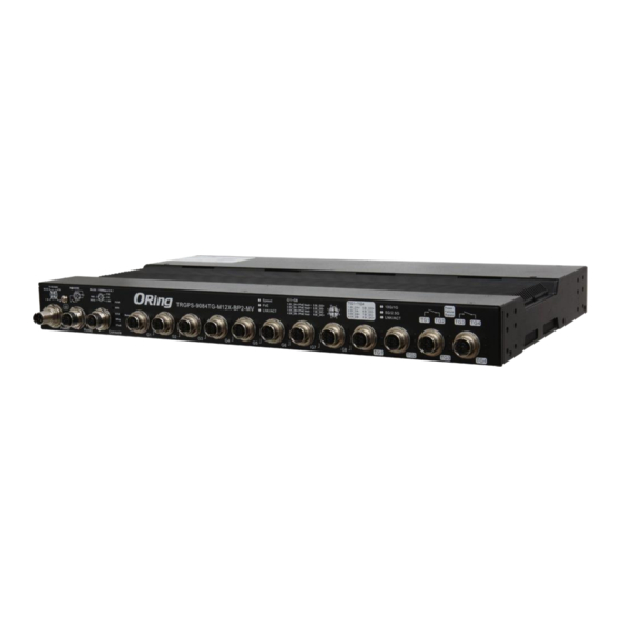
1.1 About the TRGPS-9084TG-M12X-BP2-MV ORing’s TransporterTM series managed Ethernet switches are designed for industrial applications such as rolling stock, vehicle, and railway. The TRGPS-9084TG-M12X-BP2-MV, which is compliant with the EN50155 standard, is a managed 10G/2.5G Redundant Ring Ethernet switch with 8x10/100/1000Base-T(X) P.S.E. ports and 4x10GBase-T ports which is specifically designed for the toughest and fully compliant with EN50155 requirement. -
Page 8: Hardware Specifications
TRGPS-9084TG-M12X-BP2-MV User Manual Supports IEEE 802.3az Energy-Efficient Ethernet technology Supports SMTP client Supports IP-based bandwidth management Supports application-based QoS management Supports Device Binding security Supports DOS/DDOS auto prevention IGMP v2/v3 (IGMP snooping support) for filtering multicast traffic ... -
Page 9: Hardware Overview
TRGPS-9084TG-M12X-BP2-MV User Manual ardware Overview 2.1 Front Panel The device provides the following ports on the front panel. Ethernet ports use M12 X-Code type , Console and relay ports use M12 A-Code type , to ensure tight, robust connections, as well as reliable operation against environmental disturbances, such as vibration and shock. -
Page 10: Front Panel Led
TRGPS-9084TG-M12X-BP2-MV User Manual 2.2 Front Panel LED Color Status Description Green DC power module 1 activated Green Device operating in Ring Master mode Ring enabled Ring Green Blinking Ring structure is broken Errors occur (i.e. power failure or port Fault... -
Page 11: Bypass Technology
TRGPS-9084TG-M12X-BP2-MV User Manual 2.3 Bypass Technology When a device connected to other devices through a switch without bypass function, the device will lose connection if he switch loses power as traffic will not be able to flow through the link (as shown in the figure below). -
Page 12: Hardware Installation
TRGPS-9084TG-M12X-BP2-MV User Manual ardware Installation 3.1 Rack-mount Installation Rack-mount Measurement (Unit = mm) Follow the following steps to install the switch to a rack. Step 1: Attach the mounting brackets to the front left and right sides of the switch using 4... -
Page 13: Wiring
TRGPS-9084TG-M12X-BP2-MV User Manual 3.2 Wiring WARNING Do not disconnect modules or wires unless power has been switched off or the area is known to be non-hazardous. The devices may only be connected to the supply voltage shown on the type plate. -
Page 14: Redundant Power Inputs
TRGPS-9084TG-M12X-BP2-MV User Manual 3.2.3 Redundant Power Inputs The switch provides two sets of power supply on a M23 5-pin connector to enable dual power inputs. Step 1: Insert a power cable to the power connector on the device. Step 2: Rotate the outer ring of the cable connector until a snug fit is achieved. Make sure the connection is tight. -
Page 15: Connection
TRGPS-9084TG-M12X-BP2-MV User Manual 3.3 Connection 3.3.1 Cables 10/100/1000BASE-T(X) P SSIGNMENTS The device provides Ethernet ports in M12 connector type. According to the link type, the switch uses CAT 3, 4, 5,5e UTP cables to connect to any other network devices (PCs, servers, switches, routers, or hubs). - Page 16 TRGPS-9084TG-M12X-BP2-MV User Manual Below is the pin assignment for the Ethernet ports. 10/100/1000Base-T(X) M12 port Pin Number Assignment BI_DC+ BI_DD+ BI_DD- BI_DA- BI_DB+ BI_DA+ BI_DC- BI_DB- 10/100/1000Base-T(X) P.S.E. M12 port Pin Number Assignment BI_DC+ BI_DD+ BI_DD- BI_DA- with PoE Vout+...
-
Page 17: O-Ring/O-Chain
TRGPS-9084TG-M12X-BP2-MV User Manual 1000Base-T MDI/MDI-X Pin Assignments: Pin Number MDI port MDI-X port BI_DA+ BI_DB+ BI_DA- BI_DB- BI_DB+ BI_DA+ BI_DC+ BI_DD+ BI_DC- BI_DD- BI_DB- BI_DA- BI_DD+ BI_DC+ BI_DD- BI_DC- Note: “+” and “-” signs represent the polarity of the wires that make up each wire pair. - Page 18 TRGPS-9084TG-M12X-BP2-MV User Manual Coupling Ring If you already have two O-Ring topologies and would like to connect the rings, you can form them into a coupling ring. All you need to do is select two switches from each ring to be connected, for example, switch A and B from Ring 1 and switch C and D from ring 2.
- Page 19 TRGPS-9084TG-M12X-BP2-MV User Manual Dual Homing If you want to connect your ring topology to a RSTP network environment, you can use dual homing. Choose two switches (Switch A & B) from the ring for connecting to the switches in the RSTP network (core switches).
- Page 20 TRGPS-9084TG-M12X-BP2-MV User Manual O-Chain When connecting multiple O-Rings to meet your expansion demand, you can create an O-Chain topology through the following steps. 1. Select two switches from the chain (Switch A & B) that you want to connect to the O-Ring and connect them to the switches in the ring (Switch C &...
-
Page 21: Redundancy
4.1 O-Ring 4.1.1 Introduction O-Ring is ORing's proprietary redundant ring technology, with recovery time of less than 30 milliseconds (in full-duplex Gigabit operation) or 10 milliseconds (in full-duplex Fast Ethernet operation) and up to 250 nodes. The ring protocols identify one switch as the master of the network, and then automatically block packets from traveling through any of the network’s... - Page 22 TRGPS-9084TG-M12X-BP2-MV User Manual Label Description Check to enable O-Ring topology. Redundant Ring Only one ring master is allowed in a ring. However, if more than one switches are set to enable Ring Master, the switch Ring Master with the lowest MAC address will be the active ring master and the others will be backup masters.
-
Page 23: Open-Ring
4.2 OPEN-Ring 4.2.1 Introduction Open-Ring is a technology developed by ORing to enhance ORing switches’ interoperability with other vendors’ products. With this technology, you can add any ORing switches to the network based on other ring technologies. 4.2.2 Configurations Label... -
Page 24: O-Chain
Ring Port 4.3 O-Chain 4.3.1 Introduction O-Chain is ORing’s revolutionary network redundancy technology which enhances network redundancy for any backbone networks, providing ease-of-use and maximum fault-recovery swiftness, flexibility, compatibility, and cost-effectiveness in a set of network redundancy topologies. The self-healing Ethernet technology designed for distributed and complex... -
Page 25: Bypass
TRGPS-9084TG-M12X-BP2-MV User Manual Label Description Enable Check to enable O-Chain function Ring Port The first port connecting to the ring Ring Port The second port connecting to the ring An O-Chain topology must begin with edge ports. The ports with a... -
Page 26: Bypass & Ring Topology
TRGPS-9084TG-M12X-BP2-MV User Manual Figure 2 4.4.2 Bypass & Ring Topology Bypass provides redundancy during device failure and O-Ring provides redundancy when links are broken. Together the two will provide users with dual protection when links and devices are broken. In a ring topology where switches are not bypass-enabled, the backup link will be activated immediately when one of the links is down, thereby ensuring uninterrupted data transmission. - Page 27 TRGPS-9084TG-M12X-BP2-MV User Manual Fast Ethernet Networks Fiber Networks When a link between two switches fails following the breakdown of the switch, the backup link will be activated. Data will then be transmitted via the backup path (see below). Fast Ethernet Networks...
-
Page 28: Mrp (*Note)
TRGPS-9084TG-M12X-BP2-MV User Manual Fiber Networks Note: The maximum cable length for copper ports is 100 meters and 20km for fiber ports. When data bypasses the inactive switch(s) to another active switch, the distance between the two active switches must be within the maximum length, otherwise transmission will fail. -
Page 29: Stp/Rstp/Mstp
TRGPS-9084TG-M12X-BP2-MV User Manual set to be Manager, the MRP topology will fail. React on Link Change Faster mode. Enabling this function will cause MRP topology to converge more rapidly. This function only can be set in MRP (Advanced mode) manager switch. - Page 30 TRGPS-9084TG-M12X-BP2-MV User Manual Bridge. The current state of the Topology Change Flag for the bridge Topology Flag instance. Topology Change Last The time since last Topology Change occurred. Click to refresh the page immediately. Refresh Check this box to enable an automatic refresh of the page at Auto-refresh regular intervals.
- Page 31 TRGPS-9084TG-M12X-BP2-MV User Manual This page displays the STP port statistics for the currently selected switch. Label Description The switch port number to which the following settings will be Port applied. The number of RSTP configuration BPDUs received/transmitted RSTP on the port...
-
Page 32: Mstp
TRGPS-9084TG-M12X-BP2-MV User Manual The delay used by STP bridges to transit root and designated Forward Delay ports to forwarding (used in STP compatible mode). The range of valid values is 4 to 30 seconds. The maximum time the information transmitted by the root bridge Max Age is considered valid. - Page 33 TRGPS-9084TG-M12X-BP2-MV User Manual Label Description Port The switch port number of the corresponding STP CIST (and MSTI) port Configures the path cost incurred by the port. Auto will set the path cost according to the physical link speed by using the 802.1D-recommended values.
- Page 34 TRGPS-9084TG-M12X-BP2-MV User Manual Label Description The name which identifies the VLAN to MSTI mapping. Bridges must share the name and revision (see below), as well as the Configuration Name VLAN-to-MSTI mapping configurations in order to share spanning trees for MSTIs (intra-region). The name should not exceed 32 characters.
-
Page 35: Cist
TRGPS-9084TG-M12X-BP2-MV User Manual This page allows you to examine and change the configurations of current STP MSTI bridge instance priority. Label Description The bridge instance. CIST is the default instance, which is always MSTI active. Indicates bridge priority. The lower the value, the higher the Priority priority. - Page 36 TRGPS-9084TG-M12X-BP2-MV User Manual Label Description The switch port number to which the following settings will be Port applied. STP Enabled Check to enable STP for the port Configures the path cost incurred by the port. Auto will set the path cost according to the physical link speed by using the 802.1D-recommended values.
-
Page 37: Fast Recovery
TRGPS-9084TG-M12X-BP2-MV User Manual can be set by a network administrator to prevent bridges outside a core region of the network from influencing the active spanning tree topology because those bridges are not under the full control of the administrator. This feature is also known as Root Guard. - Page 38 TRGPS-9084TG-M12X-BP2-MV User Manual Label Description Active Activate fast recovery mode port Ports can be set to 12 priorities. Only the port with the highest priority will be the active port. 1st Priority is the highest. Apply Click to activate the configurations.
-
Page 39: Management
TRGPS-9084TG-M12X-BP2-MV User Manual anagement The switch can be controlled via a built-in web server which supports Internet Explorer (Internet Explorer 5.0 or above versions) and other Web browsers such as Chrome. Therefore, you can manage and configure the switch easily and remotely. You can also upgrade firmware via a web browser. - Page 40 TRGPS-9084TG-M12X-BP2-MV User Manual After logging in, you can see the information of the switch as below. On the left hand side of the management interface shows links to various settings. You can click on the links to access the configuration pages of different functions.
-
Page 41: Basic Settings
TRGPS-9084TG-M12X-BP2-MV User Manual 6.1 Basic Settings Basic Settings allow you to configure the basic functions of the switch. 6.1.1 System Information This page shows the general information of the switch. Label Description An administratively assigned name for the managed node. By convention, this is the node's fully-qualified domain name. -
Page 42: Auth Method
TRGPS-9084TG-M12X-BP2-MV User Manual 6.1.2 Auth Method Authentication Method Configuration The authentication section allows you to configure how a user is authenticated when he logs into the switch via one of the management client interfaces. Label Description Client The management client for which the configuration below applies. -
Page 43: Users
TRGPS-9084TG-M12X-BP2-MV User Manual to CLI commands according to his privilege level. . tacacs: Use remote TACACS+ server(s) for command authorization. If all remote servers are offline, the user is granted access to CLI commands according to his privilege level. Accounting Method Configuration The accounting section allows you to configure command and exec (login) accounting. - Page 44 TRGPS-9084TG-M12X-BP2-MV User Manual Label Description User Name A string identifying the user name that this entry should belong to. The allowed string length is 1 to 31. The valid user name can be letters, numbers and underscores. Password The password of the user. The allowed string length is 0 to 31.
- Page 45 TRGPS-9084TG-M12X-BP2-MV User Manual Label Description Group Name The name identifying the privilege group. In most cases, a privilege level group consists of a single module (e.g. LACP, RSTP or QoS), but a few of them contains more than one. The...
-
Page 46: Ip Settings
TRGPS-9084TG-M12X-BP2-MV User Manual 6.1.4 IP Settings This page allows you to configure IP information for the switch. You can configure the settings of the device operating in host or router mode. IP Configuration This page provides an overview of the privilege levels. - Page 47 TRGPS-9084TG-M12X-BP2-MV User Manual Configured IPv6 Explicitly provide the valid IPv6 unicast (except linklocal) address of the DNS Server. Make sure the configured DNS server could be reachable (e.g. via PING6) for activating DNS service. From this DHCPv6 interface Specify from which DHCPv6-enabled interface a provided DNS server should be preferred.
- Page 48 TRGPS-9084TG-M12X-BP2-MV User Manual The IPv4 network mask, in number of bits (prefix length). Valid values are between 0 and 30 bits for an IPv4 address. IPv4 Mask If DHCP is enabled, this field configures the fallback address network mask. The field may be left blank if IPv4 operation on the interface is not desired - or no DHCP fallback address is desired.
-
Page 49: Ip Status
TRGPS-9084TG-M12X-BP2-MV User Manual in the VLAN or there is indeed other device occupying the same hardware address as the device in the VLAN. After making sure the specific link-local address is unique on the IPv6 link in use, delete and then add the specific IPv6 interface to restart the IPv6 operations on this interface. -
Page 50: Daylight Saving Time
TRGPS-9084TG-M12X-BP2-MV User Manual IP Address The IP address of the entry. The Link (MAC) address for which a binding to the IP address given Link Address exist. 6.1.6 Daylight Saving Time Label Description Time Zone: Set the switch location time zone. The following table lists the different location time zone for your reference. - Page 51 TRGPS-9084TG-M12X-BP2-MV User Manual duration for single time configuration. ( Default : Disabled ). Start Time Settings: Set up the start time of the daylight saving time period. End Time Settings: Set up the ending time of the daylight saving time period.
-
Page 52: Https
TRGPS-9084TG-M12X-BP2-MV User Manual Zone 1 BT - Baghdad, USSR Zone 2 +3 hours 3 pm ZP4 - USSR Zone 3 +4 hours 4 pm ZP5 - USSR Zone 4 +5 hours 5 pm ZP6 - USSR Zone 5 +6 hours... -
Page 53: Ssh
6.1.9 DBU01 Option Config DBU01 is ORing Design ,backup/ restore unit . user can use DBU-01 Quickly restore/ backup switch configure , don’t need use PC., In this page , user can enable or disable , ORing Industrial Networking Corp... -
Page 54: Lldp
TRGPS-9084TG-M12X-BP2-MV User Manual 6.1.10 LLDP LLDP Configurations This page allows you to examine and configure current LLDP port settings. Label Description The switch periodically transmits LLDP frames to its neighbors to update the network discovery information. The interval between Tx Interval each LLDP frame is determined by the Tx Interval value which must be between 5 - 32768 seconds. - Page 55 TRGPS-9084TG-M12X-BP2-MV User Manual Label Description Interface The switch interface name of the logical LLDP interface. Select a LLDP mode from the drop down list. Rx only: The switch will not send out LLDP information, but LLDP information from neighbor units is analyzed.
- Page 56 TRGPS-9084TG-M12X-BP2-MV User Manual Label Description Local Port The port that you use to transmits and receives LLDP frames. The identification number of the neighbor sending out the LLDP Chassis ID frames. The identification of the neighbor port Remote Port ID System Name The name advertised by the neighbor.
- Page 57 TRGPS-9084TG-M12X-BP2-MV User Manual Global Counters Label Description Clear Global If checked the global counters are cleared when Clear is pressed. Counters Neighbor entries Shows the time when the last entry was last deleted or added. It also shows the time elapsed since the last change was detected.
-
Page 58: Ntp
TRGPS-9084TG-M12X-BP2-MV User Manual table when a given port links down, an LLDP shutdown frame is received, or when the entry ages out. Each LLDP frame can contain multiple pieces of information, TLVs Discarded known as TLVs (Type Length Value). If a TLV is malformed, it will be counted and discarded. -
Page 59: Upnp
TRGPS-9084TG-M12X-BP2-MV User Manual fifth in sequence if any of them fails. The polling interval is fixed at 15 minutes. 6.1.12 Upnp UPnP is an acronym for Universal Plug and Play. The goals of UPnP are to allow devices to connect seamlessly and to simplify the implementation of networks in the home (data sharing,... -
Page 60: Modbustcp
TRGPS-9084TG-M12X-BP2-MV User Manual 6.1.13 ModbusTCP http://www.modbus.org/ Support Modbus TCP. (About Modbus please reference The following table describes the labels in this screen. Label Description Mode Enable or Disalble Modbus TCP function 6.1.14 Ethernet/IP EtherNet/IP is an industrial network protocol that adapts the Common Industrial Protocol to standard Ethernet.[1] EtherNet/IP is one of the leading industrial protocols in the United States... -
Page 61: Backup/Restore Configurations
TRGPS-9084TG-M12X-BP2-MV User Manual 6.1.15 Backup/Restore Configurations You can save/view or load switch configurations. 6.1.16 Firmware Update This page allows you to update the firmware of the switch. ORing Industrial Networking Corp... -
Page 62: Dhcp
TRGPS-9084TG-M12X-BP2-MV User Manual 6.2 DHCP 6.2.1 DHCP Server This page configures global mode and VLAN mode to enable/disable DHCP server per system and per VLAN.and per VLAN. Mode Label Description Global Mode Mode Configure the operation mode per system. Possible modes are: Enabled: Enable DHCP server per system. - Page 63 TRGPS-9084TG-M12X-BP2-MV User Manual Then, you will see the disabled VLAN range is removed from the DHCP Server mode configuration page. Indicate the operation mode per VLAN. Possible modes are: Mode Enabled: Enable DHCP server per VLAN. Disabled: Disable DHCP server pre VLAN.
- Page 64 TRGPS-9084TG-M12X-BP2-MV User Manual Network: the pool defines a pool of IP addresses to service more than one DHCP client. Host: the pool services for a specific DHCP client identified by client identifier or hardware address. If "-" is displayed, it means not defined.
- Page 65 TRGPS-9084TG-M12X-BP2-MV User Manual client. That is, the pool is of host type. Expired Binding Number of bindings that their lease time expired or they are cleared from Automatic/Manual type bindings. DHCP Message Received Counters Number of DHCP DISCOVER messages received.
-
Page 66: Dhcp Relay
TRGPS-9084TG-M12X-BP2-MV User Manual Declined IP Display IP addresses declined by DHCP clients. Label Description Declined IP List of IP addresses declined. 6.2.2 DHCP Relay DHCP relay is used to forward and transfer DHCP messages between the clients and the server when they are not in the same subnet domain. You can configure the function in this page. - Page 67 TRGPS-9084TG-M12X-BP2-MV User Manual Mode DHCP option 82 circuit ID format is "[vlan_id][module_id][port_no]". The first four characters represent the VLAN ID, and the fifth and sixth characters are the module ID. In stand-alone devices, the module ID always equals to 0; in stacked devices, it means switch ID.
- Page 68 TRGPS-9084TG-M12X-BP2-MV User Manual Transmit to Sever The number of packets relayed from the client to the server Transmit Error The number of packets with errors when being sent to clients The number of packets received from the server Receive from Server...
-
Page 69: Dhcp Snooping
TRGPS-9084TG-M12X-BP2-MV User Manual 6.2.3 DHCP Snooping Snooping Configure DHCP Snooping on this page. Label Description Indicates the DHCP snooping mode operation. Possible modes Snooping Mode are: Enabled: Enable DHCP snooping mode operation. When DHCP snooping mode operation is enabled, the DHCP request messages will be forwarded to trusted ports and only allow reply packets from trusted ports. - Page 70 TRGPS-9084TG-M12X-BP2-MV User Manual Label Description MAC Address User MAC address of the entry. VLAN-ID in which the DHCP traffic is permitted. VLAN ID Source Port Switch Port Number for which the entries are displayed. IP Address User IP address of the entry.
- Page 71 TRGPS-9084TG-M12X-BP2-MV User Manual Label Description Rx and Tx Discover The number of discover (option 53 with value 1) packets received and transmitted. Rx and Tx Offer The number of offer (option 53 with value 2) packets received and transmitted. Rx and Tx Request The number of request (option 53 with value 3) packets received and transmitted.
-
Page 72: Port Setting
TRGPS-9084TG-M12X-BP2-MV User Manual 6.3 Port Setting Port Setting allows you to manage individual ports of the switch, including traffic, power, and trunks. 6.3.1 Port Control This page shows current port configurations. Ports can also be configured here. Label Description Port This is the logical port number for this row. - Page 73 TRGPS-9084TG-M12X-BP2-MV User Manual duplex mode. 1Gbps FDX - Forces the port in 1Gbps full duplex 2.5Gbps FDX - Forces the Serdes port in 2.5Gbps full duplex mode. 10Gbps FDX - Forces the Serdes port in 2.5Gbps full duplex mode. SFP_Auto_AMS - Automatically determines the speed of the SFP.
- Page 74 TRGPS-9084TG-M12X-BP2-MV User Manual column indicates whether pause frames on the port are transmitted. The Rx and Tx settings are determined by the result of the last Auto Negotiation. Check the configured column to use flow control. This setting is related to the setting for Configured Link Speed.
-
Page 75: Port Trunk
TRGPS-9084TG-M12X-BP2-MV User Manual 6.3.2 Port Trunk A port trunk is a group of ports that have been grouped together to function as one logical path. This method provides an economical way for you to increase the bandwidth between the switch and another networking device. In addition, it is useful when a single physical link between the devices is insufficient to handle the traffic load. - Page 76 TRGPS-9084TG-M12X-BP2-MV User Manual Label Description Group ID Indicates the ID of each aggregation group. Normal means no aggregation. Only one group ID is valid per port. Port Members Lists each switch port for each group ID. Select a radio button to include a port in an aggregation, or clear the radio button to remove the port from the aggregation.
- Page 77 TRGPS-9084TG-M12X-BP2-MV User Manual aggregation and the ports must be in the same speed in each group. The Key value varies with the port, ranging from 1 to 65535. Auto will set the key according to the physical link speed (10Mb = 1, 100Mb = 2, 1Gb = 3). Specific allows you to enter a user-defined value.
- Page 78 TRGPS-9084TG-M12X-BP2-MV User Manual When connecting the device to other manufactures’ devices, Partner Key you may need to configure LACP partner key. Partner key is the operational key value assigned to the port associated with this link by the Partner. Last Changed The time since this aggregation is changed.
- Page 79 TRGPS-9084TG-M12X-BP2-MV User Manual Check to enable an automatic refresh of the page at regular Auto-refresh intervals LACP Port Statistics This page provides an overview of the LACP statistics for all ports. Label Description Switch port number Port LACP Transmitted The number of LACP frames sent from each port...
-
Page 80: Loop Protection
TRGPS-9084TG-M12X-BP2-MV User Manual 6.3.3 Loop Protection This feature prevents loop attack. When receiving loop packets, the port will be disabled automatically, preventing the loop attack from affecting other network devices. Configuration Label Description Enable Loop Protection Activate loop protection functions (as a whole) -
Page 81: Vlan
TRGPS-9084TG-M12X-BP2-MV User Manual 6.4 VLAN 6.4.1 VLAN Membership A VLAN is a group of end devices with a common set of requirements, independent of physical location. With the same attributes as a physical LAN, VLANs enable you to group end devices even if they are not located physically on the same LAN segment. - Page 82 TRGPS-9084TG-M12X-BP2-MV User Manual Port VLAN Configuration Label Description Port This is the logical port number of this row. The port mode (default is Access) determines the fundamental behavior of the port in question. A port can be in one of three modes as described below.
- Page 83 TRGPS-9084TG-M12X-BP2-MV User Manual limited by the use of Allowed VLANs Frames classified to a VLAN that the port is not a member of are discarded By default, all frames but frames classified to the Port VLAN (a.k.a. Native VLAN) get tagged on egress.
- Page 84 TRGPS-9084TG-M12X-BP2-MV User Manual tag, if a tag is required. Unaware: On ingress, all frames, whether carrying a VLAN tag or not, get classified to the Port VLAN, and possible tags are not removed on egress. C-Port: On ingress, frames with a VLAN tag with TPID = 0x8100 get classified to the VLAN ID embedded in the tag.
- Page 85 TRGPS-9084TG-M12X-BP2-MV User Manual the port is not a member of are accepted and forwarded to the switch engine. However, the port will never transmit frames classified to VLANs that it is not a member of. Hybrid ports allow for changing the type of frames that are accepted on ingress.
-
Page 86: Membership Status
TRGPS-9084TG-M12X-BP2-MV User Manual dynamically adding ports to VLANs. The trick is to mark such VLANs as forbidden on the port in question. The syntax is identical to the syntax used in the Enabled VLANs field. By default, the field is left blank, which means that the port may become a member of all possible VLANs. -
Page 87: Port Status
TRGPS-9084TG-M12X-BP2-MV User Manual 6.4.3 Port Status This page provides VLAN Port Status Label Description Various internal software modules may use VLAN services to configure VLAN port configuration on the fly. The drop-down list on the right allows for selecting between... -
Page 88: Private Vlan
TRGPS-9084TG-M12X-BP2-MV User Manual port to have. The field is empty if not overridden by the selected user. Shows the Tx Tag requirements (Tag All, Tag PVID, Tag UVID, Untag All, Untag PVID, Untag UVID) that a given user has on a Tx Tag port. - Page 89 TRGPS-9084TG-M12X-BP2-MV User Manual Label Description Check to delete the entry. It will be deleted during the next Delete save. Private VLAN ID Indicates the ID of this particular private VLAN. MAC Address The MAC address for the entry. A row of check boxes for each port is displayed for each private VLAN ID.
-
Page 90: Gvrp
TRGPS-9084TG-M12X-BP2-MV User Manual Label Description A check box is provided for each port of a private VLAN. When checked, port isolation is enabled for that port. Port Members When unchecked, port isolation is disabled for that port. By default, port isolation is disabled for all ports. - Page 91 TRGPS-9084TG-M12X-BP2-MV User Manual units of one hundredth of a second. The default is 1000cs. When GVRP is enabled, a maximum number of VLANs supported by GVRP is specified. By default this number is Max number of VLANs 20. This number can only be changed when GVRP is turned off.
-
Page 92: Snmp
TRGPS-9084TG-M12X-BP2-MV User Manual 6.5 SNMP 6.5.1 SNMP System Configurations Label Description Indicates existing SNMP mode. Possible modes include: Mode Enabled: enable SNMP mode Disabled: disable SNMP mode Indicates the supported SNMP version. Possible versions include: SNMP v1: supports SNMP version 1. -
Page 93: Trap
TRGPS-9084TG-M12X-BP2-MV User Manual 6.5.2 Trap SNMP Trap Detailed Configuration Label Description Indicates which trap Configuration's name for configuring. The Trap Config Name allowed string length is 1 to 32, and the allowed content is ASCII characters from 33 to 126. - Page 94 TRGPS-9084TG-M12X-BP2-MV User Manual dash. Indicates the SNMP trap destination IPv6 address. IPv6 address is in 128-bit records represented as eight fields of up to four hexadecimal digits with a colon separating each field (:). For example, 'fe80::215:c5ff:fe03:4dc7'. The symbol '::' is a special syntax that can be used as a shorthand way of representing multiple 16-bit groups of contiguous zeros;...
-
Page 95: Snmp Community Configurations
TRGPS-9084TG-M12X-BP2-MV User Manual SNMP Trap Event Label Description Enable/disable that the Interface group's traps. Possible traps are: System Warm Start: Enable/disable Warm Start trap. Cold Start: Enable/disable Cold Start trap. Indicates that the Interface group's traps. Possible traps are: Indicates... -
Page 96: Snmp User Configurations
TRGPS-9084TG-M12X-BP2-MV User Manual Label Description Check to delete the entry. It will be deleted during the next save. Delete Indicates the community access string to permit access to Community SNMPv3 agent. The allowed string length is 1 to 32, and only ASCII characters from 33 to 126 are allowed. -
Page 97: Snmp Group Configurations
TRGPS-9084TG-M12X-BP2-MV User Manual Possible security models include: NoAuth, NoPriv: no authentication and none privacy Auth, NoPriv: Authentication and no privacy Auth, Priv: Authentication and privacy The value of security level cannot be modified if the entry already exists, which means the value must be set correctly at the time of entry creation. -
Page 98: Snmp View Configurations
TRGPS-9084TG-M12X-BP2-MV User Manual Label Description Delete Check to delete the entry. It will be deleted during the next save. Indicates the security model that this entry should belong to. Possible security models included: Security Model v1: Reserved for SNMPv1. v2c: Reserved for SNMPv2c. -
Page 99: Snmp Access Configurations
TRGPS-9084TG-M12X-BP2-MV User Manual A string identifying the view name that this entry should belong to. View Name The allowed string length is 1 to 32, and only ASCII characters from 33 to 126 are allowed. Indicates the view type that this entry should belong to. Possible view... -
Page 100: Rmon
TRGPS-9084TG-M12X-BP2-MV User Manual Indicates the security model that this entry should belong to. Possible security models include: Security Level NoAuth, NoPriv: no authentication and no privacy Auth, NoPriv: Authentication and no privacy Auth, Priv: Authentication and privacy The name of the MIB view defining the MIB objects for which this Read View Name request may request the current values. - Page 101 TRGPS-9084TG-M12X-BP2-MV User Manual Label Description Delete Check to delete the entry. It will be deleted during the next save. Indicates the index of the entry. The range is from 1 to 65535. Indicates the port ID which wants to be monitored. If in stacking...
- Page 102 TRGPS-9084TG-M12X-BP2-MV User Manual discarded because of the unknown or un-support protocol. OutOctets: The number of octets transmitted out of the interface , including framing characters. OutUcastPkts: The number of uni-cast packets that request to transmit. OutNUcastPkts: The number of broad-cast and multi-cast packets that request to transmit.
- Page 103 TRGPS-9084TG-M12X-BP2-MV User Manual Label Description Check to delete the entry. It will be deleted during the next save. Delete Indicates the index of the entry. The range is from 1 to 65535. Indicates this event, the string length is from 0 to 127, default is a null Desc string.
- Page 104 TRGPS-9084TG-M12X-BP2-MV User Manual octets, inclusive, but had either a bad Frame Check Sequence (FCS) with an integral number of octets (FCS Error) or a bad FCS with a non-integral number of octets (Alignment Error). Under-size The total number of packets received that were less than 64 octets.
- Page 105 TRGPS-9084TG-M12X-BP2-MV User Manual The total number of events in which packets were dropped by the Drop probe due to lack of resources. The total number of octets of data (including those in bad packets) Octets received on the network. The total number of packets (including bad packets, broadcast Pkts packets, and multicast packets) received.
- Page 106 TRGPS-9084TG-M12X-BP2-MV User Manual Label Description Indicates the index of Alarm control entry. Indicates the interval in seconds for sampling and comparing the Interval rising and falling threshold. Indicates the particular variable to be sampled Variable The method of sampling the selected variable and calculating the Sample Type value to be compared against the thresholds.
-
Page 107: Traffic Prioritization
TRGPS-9084TG-M12X-BP2-MV User Manual 6.6 Traffic Prioritization 6.6.1 Storm Control There is a unicast storm rate control, multicast storm rate control, and a broadcast storm rate control. These only affect flooded frames, i.e. frames with a (VLAN ID, DMAC) pair not present on the MAC Address table. - Page 108 TRGPS-9084TG-M12X-BP2-MV User Manual Port Storm Policer Configuration Port storm policers for all switch ports are configured on this page. There is a storm policer for unicast frames, broadcast frames and unknown (flooded) frames. The displayed settings are: Label Description The frame type for which the configuration below applies.
-
Page 109: Port Classification
TRGPS-9084TG-M12X-BP2-MV User Manual 6.6.2 Port Classification QoS is an acronym for Quality of Service. It is a method to achieve efficient bandwidth utilization between individual applications or protocols. Label Description Port The port number for which the configuration below applies Controls the default QoS class All frames are classified to a QoS class. -
Page 110: Port Tag Remaking
TRGPS-9084TG-M12X-BP2-MV User Manual frame is classified to a DP level that is equal to the DEI value in the tag. Otherwise the frame is classified to the default DP level. If the port is VLAN aware, the frame is tagged, and Tag Class is enabled, then the frame is classified to a DP level that is mapped from the PCP and DEI value in the tag. -
Page 111: Port Dscp
TRGPS-9084TG-M12X-BP2-MV User Manual Label Description The switch port number to which the following settings will be Port applied. Click on the port number to configure tag remarking Shows the tag remarking mode for this port Classified: use classified PCP/DEI values... -
Page 112: Port Policing
TRGPS-9084TG-M12X-BP2-MV User Manual specific DSCP. All: classify all DSCP Port egress rewriting can be one of the following options: Disable: no Egress rewrite Enable: rewrite enabled without remapping Remap DP Unaware: DSCP from the analyzer is remapped and the frame is remarked with a remapped DSCP value. -
Page 113: Queue Policing
TRGPS-9084TG-M12X-BP2-MV User Manual kbps, Mbps, fps, or kfps. The default value is kbps. If Flow Control is enabled and the port is in Flow Control mode, then pause frames are sent instead of being Flow Control discarded. 6.6.6 Queue Policing This page allows you to configure Queue Policer settings for all switch ports. - Page 114 TRGPS-9084TG-M12X-BP2-MV User Manual Label Description Controls whether the scheduler mode is Strict Priority or Scheduler Mode Weighted on this switch port Queue Shaper Check to enable queue shaper for individual switch ports Enable Configures the rate of each queue shaper. The default value is Queue Shaper Rate 500.
- Page 115 TRGPS-9084TG-M12X-BP2-MV User Manual and it is restricted to 1 to 3300 when the Unit is Mbps. Configures the unit of measurement for each port shaper rate as Port Shaper Unit kbps or Mbps. The default value is kbps. Weighted Label...
-
Page 116: Port Scheduler
TRGPS-9084TG-M12X-BP2-MV User Manual kbps, and it is restricted to 1 to 3300 when the Unit is Mbps. Queue Shaper Allows the queue to use excess bandwidth Excess Configures the weight of each queue. The default value is 17. Queue Scheduler This value is restricted to 1 to 100. -
Page 117: Dscp-Based Qos
TRGPS-9084TG-M12X-BP2-MV User Manual Label Description The switch port number to which the following settings will be Port applied. Click on the port number to configure the shapers Mode Shows disabled or actual queue shaper rate - e.g. "800 Mbps" Shows disabled or actual port shaper rate - e.g. "800 Mbps"... -
Page 118: Dscp Translation
TRGPS-9084TG-M12X-BP2-MV User Manual DSCP values are mapped to a specific QoS class and drop precedence level. Frames with untrusted DSCP values are treated as a non-IP frame. QoS Class QoS class value can be any number from 0-7. Drop Precedence Level (0-1) 5.6.11 DSCP Translation... -
Page 119: Dscp Classification
TRGPS-9084TG-M12X-BP2-MV User Manual Remap DP0: controls the remapping for frames with DP level 0. You can select the DSCP value from a selected menu to which you want to remap. DSCP value ranges from 0 to 63. Remap DP1: controls the remapping for frames with DP level 1. - Page 120 TRGPS-9084TG-M12X-BP2-MV User Manual Label Description Port Members Check to include the port in the QCL entry. By default, all ports are included. Key Parameters Key configurations include: Tag: value of tag, can be Any, Untag or Tag. VID: valid value of VLAN ID, can be any value from 1 to 4095 Any: user can enter either a specific value or a range of VIDs.
- Page 121 TRGPS-9084TG-M12X-BP2-MV User Manual IPv6 Note: all frame types are explained below. Allow all types of frames Ethernet Valid Ethernet values can range from 0x600 to 0xFFFF or Any' but excluding 0x800(IPv4) and 0x86DD(IPv6). The default value is Any. SSAP Address: valid SSAP (Source Service Access Point) values can range from 0x00 to 0xFF or Any.
-
Page 122: Qos Statistics( Qos Counters)
TRGPS-9084TG-M12X-BP2-MV User Manual value or port range applicable for IP protocol UDP/TCP Dport Destination TCP/UDP port: (0-65535) or Any, specific value or port range applicable for IP protocol UDP/TCP Action Parameters Class QoS class: (0-7) or Default Valid Drop Precedence Level value can be (0-1) or Default. - Page 123 TRGPS-9084TG-M12X-BP2-MV User Manual Label Description User Indicates the QCL user Indicates the index of QCE QCE# Indicates the type of frame to look for incoming frames. Possible frame types are: Any: the QCE will match all frame type. Ethernet: Only Ethernet frames (with Ether Type 0x600-0xFFFF) are Frame Type allowed.
-
Page 124: Wred
TRGPS-9084TG-M12X-BP2-MV User Manual 5.6.16 WRED This page allows you to configure the Random Early Detection (RED) settings. Through different RED configuration for the queues (QoS classes) it is possible to obtain Weighted Random Early Detection (WRED) operation between queues. The settings are global for all ports in the switch. - Page 125 TRGPS-9084TG-M12X-BP2-MV User Manual 100%. RED Drop Probability Function Min is the fill level where the queue randomly start dropping frames marked with Drop Precedence Level > 0 (yellow frames). If Max Unit is 'Drop Probability' (the green line), Max controls the drop probability when the fill level is just below 100%.
-
Page 126: Multicast
TRGPS-9084TG-M12X-BP2-MV User Manual 6.7 Multicast 6.7.1 IGMP Snooping This page provides IGMP Snooping related configurations. Label Description Snooping Enabled Check to enable global IGMP snooping Enable unregistered IPMCv4 traffic flooding. Unregistered The flooding control takes effect only when IGMP Snooping is enabled. - Page 127 TRGPS-9084TG-M12X-BP2-MV User Manual Enable to limit the number of multicast groups to which a switch port can Throttling belong. VLAN Configurations of IGMP Snooping Each page shows up to 99 entries from the VLAN table, with a default value of 20, selected by the Entries Per Page input field.
- Page 128 TRGPS-9084TG-M12X-BP2-MV User Manual Compatibility is maintained by hosts and routers taking appropriate actions depending on the versions of IGMP operating on hosts and Compatibility routers within a network. The allowed selection is IGMP-Auto, Forced IGMPv1,Forced IGMPv2, Forced IGMPv3, default compatibility value is IGMP-Auto.
- Page 129 TRGPS-9084TG-M12X-BP2-MV User Manual IGMP Snooping Status This page provides IGMP snooping status. Label Description VLAN ID The VLAN ID of the entry Querier Version Active Querier version Host Version Active Host version Querier Status Shows the Querier status as ACTIVE or IDLE...
- Page 130 TRGPS-9084TG-M12X-BP2-MV User Manual Label Description VLAN ID The VLAN ID of the group Groups The group address of the group displayed Port Members Ports under this group IPv4 SFM Information Entries in the IGMP SFM Information Table are shown on this page. The IGMP SFM (Source-Filtered Multicast) Information Table also contains the SSM (Source-Specific Multicast) information.
-
Page 131: Mvr
TRGPS-9084TG-M12X-BP2-MV User Manual shown in the Source Address field. Type Indicates the Type. It can be either Allow or Deny. Indicates whether data plane destined to the specific group address Hardware Filter / Switch from the source IPv4 address could be handled by chip or not. - Page 132 TRGPS-9084TG-M12X-BP2-MV User Manual Label Description Enable/Disable the Global MVR. The Unregistered Flooding control depends on the current MVR Mode configuration in IGMP/MLD Snooping. It is suggested to enable Unregistered Flooding control when the MVR group table is full. Check to delete the entry. The designated entry will be deleted during Delete the next save.
- Page 133 TRGPS-9084TG-M12X-BP2-MV User Manual Specify whether the traversed IGMP/MLD control frames will be sent Tagging as Untagged or Tagged with MVR VID. The default is Tagged. Specify how the traversed IGMP/MLD control frames will be sent in Priority prioritized manner. The default Priority is 0.
- Page 134 TRGPS-9084TG-M12X-BP2-MV User Manual Statistics Label Description VLAN ID The Multicast VLAN ID. IGMP/ MLD The number of Received Queries for IGMP and MLD, respectively. Queries Received IGMP / MLD Queries The number of Transmitted Queries for IGMP and MLD, respectively.
- Page 135 TRGPS-9084TG-M12X-BP2-MV User Manual MVR SFM Information Label Description VLAN ID VLAN ID of the group. Group ID of the group displayed. Groups Port Switch Port number Indicates the filtering mode maintained per (VLAN ID, port number, Mode Group Address) basis. It can be either Include or Exclude.
-
Page 136: Security
TRGPS-9084TG-M12X-BP2-MV User Manual 6.8 Security 6.8.1 Device Binding This page provides device binding configurations. Device binding is a powerful way to monitor devices and network security. Label Description Indicates the device binding operation for each port. Possible modes are: ---: disable... - Page 137 TRGPS-9084TG-M12X-BP2-MV User Manual Acton monitor the device against DDOS attacks. Indicates DDOS prevention status. Possible statuses are: ---: disable DDoS Prevention Analyzing: analyzes packet throughput for initialization Status Running: analysis completes and ready for next move Attacked: DDOS attacks occur...
- Page 138 TRGPS-9084TG-M12X-BP2-MV User Manual Label Description Link Change Disables or enables the port Only log it Simply sends logs to the log server Shunt Down the Disables the port Port Reboot Device Disables or enables PoE power DDoS Prevention This page provides DDOS Prevention configurations. The switch can monitor ingress packets, and perform actions when DDOS attack occurred on this port.
- Page 139 TRGPS-9084TG-M12X-BP2-MV User Manual High: high sensibility Indicates the types of DDoS attack packets to be monitored. Possible types are: RX Total: all ingress packets RX Unicast: unicast ingress packets Packet Type RX Multicast: multicast ingress packets RX Broadcast: broadcast ingress packets...
- Page 140 TRGPS-9084TG-M12X-BP2-MV User Manual Label Description Indicates device types. Possible types are: --- (no specification), Type IP Camera, IP Phone, Access Point, PC, PLC, and Network Video Recorder Indicates location information of the device. The information can Location Address be used for Google Mapping.
-
Page 141: Access Management
TRGPS-9084TG-M12X-BP2-MV User Manual Label Description Enables or disables stream monitoring of the port Mode Indicates the action to take when the stream gets low. Possible actions are: Action ---: no action Log it: simply logs the event 6.8.2 Access Management Configuration You can configure access management table on this page. -
Page 142: Ip Source Guard
TRGPS-9084TG-M12X-BP2-MV User Manual The host can access the switch from HTTP/HTTPS interface if the HTTP/HTTPS host IP address matches the IP address range provided in the entry. The host can access the switch from SNMP interface if the host IP SNMP address matches the IP address range provided in the entry. - Page 143 TRGPS-9084TG-M12X-BP2-MV User Manual Label Description Enable or disable this function. Mode Max Dynamic Specify the number of clients supported. Clients Static Table Label Description Delete Check to delete the entry. It will be deleted during the next save. The logical port for the settings.
-
Page 144: Acl
TRGPS-9084TG-M12X-BP2-MV User Manual IP Address Allowed source IP address. MAC Address Allowed source MAC address. 6.8.4 Ports This page allows you to configure the ACL parameters (ACE) of each switch port. These parameters will affect frames received on a port unless the frame matches a specific ACE. - Page 145 TRGPS-9084TG-M12X-BP2-MV User Manual are: Enabled: if a frame is received on the port, the port will be disabled. Disabled: port shut down is disabled. The default value is Disabled. Counter Counts the number of frames that match this ACE. Rate Limiters This page allows you to configure the rate limiter for the ACL of the switch.
- Page 146 TRGPS-9084TG-M12X-BP2-MV User Manual Label Description Indicates the ingress port to which the ACE will apply. Any: the ACE applies to any port Port n: the ACE applies to this port number, where n is the number of Ingress Port the switch port.
- Page 147 TRGPS-9084TG-M12X-BP2-MV User Manual Disabled: frames matching the ACE are not logged. Please note that system log memory capacity and logging rate is limited. Specifies the shutdown operation of the ACE. The allowed values are: Shutdown Enabled: if a frame matches the ACE, the ingress port will be disabled.
- Page 148 TRGPS-9084TG-M12X-BP2-MV User Manual specific destination address. legal format "xx-xx-xx-xx-xx-xx". Frames matching the ACE will use this DMAC value. Label Description Specifies the VLAN ID filter for the ACE Any: no VLAN ID filter is specified (VLAN ID filter status is VLAN ID Filter "don't-care").
- Page 149 TRGPS-9084TG-M12X-BP2-MV User Manual Label Description Specifies the IP protocol filter for the ACE Any: no IP protocol filter is specified ("don't-care"). Specific: if you want to filter a specific IP protocol filter with the ACE, choose this value. A field for entering an IP protocol filter appears.
- Page 150 TRGPS-9084TG-M12X-BP2-MV User Manual Specifies the fragment offset settings for the ACE. This includes settings of More Fragments (MF) bit and Fragment Offset (FRAG OFFSET) for an IPv4 frame. No: IPv4 frames whose MF bit is set or the FRAG OFFSET field is IP Fragment greater than zero must not be able to match this entry.
- Page 151 TRGPS-9084TG-M12X-BP2-MV User Manual Label Description Specifies the available ARP/RARP opcode (OP) flag for the Any: no ARP/RARP OP flag is specified (OP is "don't-care"). ARP/RARP ARP: frame must have ARP/RARP opcode set to ARP RARP: frame must have ARP/RARP opcode set to RARP.
- Page 152 TRGPS-9084TG-M12X-BP2-MV User Manual Any: no target IP filter is specified (target IP filter is "don't-care"). Host: target IP filter is set to Host. Specify the target IP address in the Target IP Address field that appears. Network: target IP filter is set to Network. Specify the target IP address and target IP mask in the Target IP Address and Target IP Mask fields that appear.
- Page 153 TRGPS-9084TG-M12X-BP2-MV User Manual must match this entry. Any: any value is allowed ("don't-care"). Specifies whether frames will meet the action according to their ARP/RARP protocol address space (PRO) settings. 0: ARP/RARP frames where the PRO is equal to IP (0x800) must not match this entry.
- Page 154 TRGPS-9084TG-M12X-BP2-MV User Manual Label Description Specifies the TCP/UDP source filter for the ACE Any: no TCP/UDP source filter is specified (TCP/UDP source filter status is "don't-care"). Specific: if you want to filter a specific TCP/UDP source filter with the TCP/UDP Source ACE, you can enter a specific TCP/UDP source value.
- Page 155 TRGPS-9084TG-M12X-BP2-MV User Manual filter with the ACE, you can enter a specific TCP/UDP destination range. A field for entering a TCP/UDP destination value appears. When Specific is selected for the TCP/UDP destination filter, you TCP/UDP can enter a specific TCP/UDP destination value. The allowed range Destination is 0 to 65535.
-
Page 156: Aaa
TRGPS-9084TG-M12X-BP2-MV User Manual Specifies the TCP URG ("urgent pointer field significant") value for the ACE 0: TCP frames where the URG field is set must not be able to match TCP URG this entry. 1: TCP frames where the URG field is set must be able to match this entry. -
Page 157: Tacacs
TRGPS-9084TG-M12X-BP2-MV User Manual The dead time, which can be set to a number between 0 and 3600 seconds, is the period during which the switch will not send new requests to a server that has failed to respond to a previous request. - Page 158 TRGPS-9084TG-M12X-BP2-MV User Manual Label Description The timeout, which can be set to a number between 3 and 3600 seconds, is the maximum time to wait for a reply from a server. If the server does not reply within this time frame, we will consider it to be dead and continue with the next enabled server (if any).
- Page 159 TRGPS-9084TG-M12X-BP2-MV User Manual Timeout The time to wait for the TACACS+ server to respond. The shared secret between the switch and the TACACS+ server. 6.8.7 RADIUS Authentication and Accounting Server Configurations This page provides an overview of the status of the RADIUS servers configurable on the authentication configuration page.
-
Page 160: Nas (802.1X)
TRGPS-9084TG-M12X-BP2-MV User Manual 6.8.8 NAS (802.1x) This page allows you to configure the IEEE 802.1X and MAC-based authentication system and port settings. The IEEE 802.1X standard defines a port-based access control procedure that prevents unauthorized access to a network by requiring users to first submit credentials for authentication. - Page 161 TRGPS-9084TG-M12X-BP2-MV User Manual Overview of 802.1X (Port-Based) Authentication In an 802.1X network environment, the user is called the supplicant, the switch is the authenticator, and the RADIUS server is the authentication server. The switch acts as the man-in-the-middle, forwarding requests and responses between the supplicant and the authentication server.
- Page 162 TRGPS-9084TG-M12X-BP2-MV User Manual configured accordingly. When authentication is complete, the RADIUS server sends a success or failure indication, which in turn causes the switch to open up or block traffic for that particular client, using static entries into the MAC Table. Only then will frames from the client be forwarded on the switch.
- Page 163 TRGPS-9084TG-M12X-BP2-MV User Manual Label Description Indicates if 802.1X and MAC-based authentication is globally enabled or disabled on the switch. If globally disabled, all ports Mode are allowed to forward frames. If checked, clients are reauthenticated after the interval specified Reauthentication Period.
- Page 164 TRGPS-9084TG-M12X-BP2-MV User Manual RADIUS server configuration has changed. It does not involve communication between the switch and the client, and therefore does not imply that a client is still present on a port (see Age Period below). Determines the period, in seconds, after which a connected client must re-authenticated.
- Page 165 TRGPS-9084TG-M12X-BP2-MV User Manual seconds. Port The port number for which the configuration below applies If NAS is globally enabled, this selection controls the port's authentication mode. The following modes are available: Force Authorized In this mode, the switch will send one EAPOL Success frame when the port link is up, and any client on the port will be allowed network access without authentication.
- Page 166 TRGPS-9084TG-M12X-BP2-MV User Manual Note: in an environment where two backend servers are enabled, the server timeout is configured to X seconds (using the authentication configuration page), and the first server in the list is currently down (but not considered dead), if the supplicant...
- Page 167 TRGPS-9084TG-M12X-BP2-MV User Manual network traffic. This allows other clients connected to the port (for instance through a hub) to piggy-back on the successfully authenticated client and get network access even though they are not authenticated individually. To overcome this security breach, use the Multi 802.1X variant.
- Page 168 TRGPS-9084TG-M12X-BP2-MV User Manual When authentication is complete, the RADIUS server sends a success or failure indication, which in turn causes the switch to open up or block traffic for that particular client, using the Port Security module. Only then will frames from the client be forwarded on the switch.
- Page 169 TRGPS-9084TG-M12X-BP2-MV User Manual Reauthenticate: schedules a reauthentication whenever the quiet-period of the port runs out (EAPOL-based authentication). For MAC-based authentication, reauthentication will be attempted immediately. The button only has effect on successfully authenticated clients on the port and will not cause the clients to be temporarily unauthorized.
- Page 170 TRGPS-9084TG-M12X-BP2-MV User Manual This page provides detailed IEEE 802.1X statistics for a specific switch port using port-based authentication. For MAC-based ports, only selected backend server (RADIUS Authentication Server) statistics is showed. Use the port drop-down list to select which port details to be displayed.
-
Page 171: Arp Inspecition
TRGPS-9084TG-M12X-BP2-MV User Manual • MAC-based Auth. Information about the last supplicant/client that attempts to authenticate. This information is available for the following administrative states: • 802.1X • MAC-based Auth. Last Supplicant/Client Info 6.8.9 ARP Inspecition This page allows you to configure the Random Early Detection (RED) settings. - Page 172 TRGPS-9084TG-M12X-BP2-MV User Manual Label Description The WRED group number for which the configuration below Group applies. The queue number (QoS class) for which the configuration below Queue applies. The Drop Precedence Level for which the configuration below applies. Enable Controls whether RED is enabled for this entry.
-
Page 173: Port Security
TRGPS-9084TG-M12X-BP2-MV User Manual 6.8.10 Port Security Limit Control This page allows you to configure limit control for port security system- or port-wise. It will limit the number of users on a given port. If the specified number is exceeded, an action is taken.. - Page 174 TRGPS-9084TG-M12X-BP2-MV User Manual exceeded, the corresponding action is taken. If the limit number is reached, the switch will take one of the following actions: None: Do not allow more than Limit MAC addresses on the port, but take no further action.
- Page 175 TRGPS-9084TG-M12X-BP2-MV User Manual Switch This page allows you to review the port security status. Label Description The full name of a module that may request Port Security User Module Name services. A one-letter abbreviation of the user module. This is used in the Abbr Users column in the port status table.
- Page 176 TRGPS-9084TG-M12X-BP2-MV User Manual service. Ready: The Port Security service is in use by at least one user module, and is awaiting frames from unknown MAC addresses to arrive. Limit Reached: The Port Security service is enabled by at least the Limit Control user module, and that module has indicated that...
-
Page 177: Warning
TRGPS-9084TG-M12X-BP2-MV User Manual Shows the date and time when this MAC address was first seen Time of Addition on the port. If at least one user module has decided to block this MAC address, it will stay in the blocked state until the hold time (measured in seconds) expires. - Page 178 TRGPS-9084TG-M12X-BP2-MV User Manual Label Description Server Mode Indicates existing server mode. When the mode operation is enabled, the syslog message will be sent to syslog server. The syslog protocol is based on UDP communications and received on UDP port 514 and...
-
Page 179: Monitor And Diag
TRGPS-9084TG-M12X-BP2-MV User Manual Label Description System Cold Start Sends out alerts when the system is restarted Power Status Sends out alerts when power is up or down SNMP Authentication Failure Sends out alert when SNMP authentication fails Redundant-Ring Topology Sends out alerts when Redundant-Ring topology... - Page 180 TRGPS-9084TG-M12X-BP2-MV User Manual Aging Configuration By default, dynamic entries are removed from the MAC after 300 seconds. This removal is called aging. You can configure aging time by entering a value in the box below in seconds; for example, Age Time seconds.
- Page 181 TRGPS-9084TG-M12X-BP2-MV User Manual Label Description Learning is done automatically as soon as a frame with unknown Auto SMAC is received. Disable No learning is done. Only static MAC entries are learned, all other frames are dropped. Note: make sure the link used for managing the switch is added to...
- Page 182 TRGPS-9084TG-M12X-BP2-MV User Manual the Entries Per Page input field. When first visited, the web page will show the first 20 entries from the beginning of the MAC Table. The first displayed will be the one with the lowest VLAN ID and the lowest MAC address found in the MAC Table.
-
Page 183: Port Statistics
TRGPS-9084TG-M12X-BP2-MV User Manual 6.10.2 Port Statistics Traffic Overview This page provides an overview of general traffic statistics for all switch ports. Label Description The switch port number to which the following settings will be Port applied. Packets The number of received and transmitted packets per port... - Page 184 TRGPS-9084TG-M12X-BP2-MV User Manual Label Description Rx and Tx Packets The number of received and transmitted (good and bad) packets The number of received and transmitted (good and bad) bytes, Rx and Tx Octets including FCS, except framing bits The number of received and transmitted (good and bad) unicast...
-
Page 185: Port Monitoring
TRGPS-9084TG-M12X-BP2-MV User Manual 1. Short frames are frames smaller than 64 bytes. 2. Long frames are frames longer than the maximum frame length configured for this port. 6.10.3 Port Monitoring You can configure port mirroring on this page. To solve network problems, selected traffic can be copied, or mirrored, to a mirror port where a frame analyzer can be attached to analyze the frame flow. -
Page 186: System Log Information
TRGPS-9084TG-M12X-BP2-MV User Manual switch to destination switch. The intermediate ports are located on this switch. Destination: the switch is an end node for monitor flow. The destination port(s) and intermediate port(s) are located on this switch. The VLAN ID points out where the monitor packet will copy to. The VLAN ID default VLAN ID is 200. - Page 187 TRGPS-9084TG-M12X-BP2-MV User Manual Label Description The ID (>= 1) of the system log entry The level of the system log entry. The following level types are supported: Notice: Log messages that represent significant condition but not errors. Level Informational: Log informational messages.
-
Page 188: Cable Diagnostics
TRGPS-9084TG-M12X-BP2-MV User Manual 6.10.5 Cable Diagnostics This page allows you to perform VeriPHY cable diagnostics Press Start to run the diagnostics. This will take approximately 5 seconds. If all ports are selected, this can take approximately 15 seconds. When completed, the page refreshes automatically, and you can view the cable diagnostics results in the cable status table. -
Page 189: Ping
TRGPS-9084TG-M12X-BP2-MV User Manual 6.10.6 Ping This page allows you to issue ICMP PING packets to troubleshoot IP connectivity issues After you press Start, five ICMP packets will be transmitted, and the sequence number and roundtrip time will be displayed upon reception of a reply. The page refreshes automatically until responses to all packets are received, or until a timeout occurs PING6 server ::10.10.132.20... -
Page 190: Poe
TRGPS-9084TG-M12X-BP2-MV User Manual PING6 server ::192.168.10.1 sendto sendto sendto sendto sendto Sent 5 packets, received 0 OK, 0 bad 6.11 POE 6.11.1 Configuration PoE (Power Over Ethernet) is a technology that transmits electrical power to devices such as IP telephones, wireless LAN access points, and IP cameras over standard Ethernet cables. - Page 191 TRGPS-9084TG-M12X-BP2-MV User Manual determined by reserved power of each port or power devices. Allocation: users can allocate the amount of power that each port reserves. The allocated/reserved power for each port/power device is specified in the Maximum Power field. Class: each port automatically determines how much power to reserve according to the class the connected power device belongs to, and then reserves the power accordingly.
-
Page 192: Status
TRGPS-9084TG-M12X-BP2-MV User Manual switch does not support backup power supply, only the primary power supply settings will be shown. If the primary power source fails, the backup power source will take over. To determine the amount of power allowed for the power device, you must configure the amount of power the primary and backup power sources can deliver. - Page 193 TRGPS-9084TG-M12X-BP2-MV User Manual be applied. PD Class Each power device is classified according to the class that defines the maximum power consumed by the PD. This setting includes five classes: Class 0: Max. power 15.4 W Class 1: Max. power 4.0 W Class 2: Max.
-
Page 194: Configuration
TRGPS-9084TG-M12X-BP2-MV User Manual 6.12 Configuration This setting allows you to activate or delete configuration files. Simply select the files to be activated or deleted and press the button. 6.12.1 Activate 6.12.2 Delete 6.13 Save You can save current configurations as a startup configuration file. -
Page 195: System Reboot
TRGPS-9084TG-M12X-BP2-MV User Manual Label Description Click to reset the configuration to factory defaults Click to return to the Port State page without resetting 6.14.2 System Reboot You can reset the stack switch on this page. After reset, the system will boot normally as if you... -
Page 196: Technical Specifications
TRGPS-9084TG-M12X-BP2-MV User Manual echnical Specifications ORing Switch Model TRGPS-9084TG-M12X-BP2-MV Physical Ports 10/100/1000Base-T(X) with P.S.E. 8 (8-pin X-coding, female connector) Ports in M12 Auto MDI/MDIX 100/1G/2.5G/10GBase-T(X) Ports in 4 (8-pin X-coding, female connector) M12 Auto MDI/MDIX Technology IEEE 802.3 for 10Base-T IEEE 802.3u for 100Base-TX... - Page 197 TRGPS-9084TG-M12X-BP2-MV User Manual Power Indicator (PWR) Green: Power LED x 1 Ring Master Indicator (R.M.) Green: Indicates that the system is operating in O-Ring Master mode Green: Indicates that the system operating in O-Ring mode O-Ring Indicator (Ring) Green Blinking: Indicates that the Ring is broken.
Need help?
Do you have a question about the TRGPS-9084TG-M12X-BP2-MV and is the answer not in the manual?
Questions and answers