Table of Contents
Advertisement
Quick Links
T
G
P
T
G
P
I
n
d
u
s
t
r
i
a
l
M
a
I
n
d
u
s
t
r
i
a
l
M
U
s
U
s
S
S
S
-
9
0
8
4
G
T
-
M
S
-
9
0
8
4
G
T
-
M
n
a
g
e
d
E
t
h
e
a
n
a
g
e
d
E
t
h
e
e
r
M
a
n
u
a
e
r
M
a
n
u
V
e
r
s
i
o
n
1
.
0
V
e
r
s
i
o
n
1
.
0
e
p
t
e
m
b
e
r
,
2
0
1
4
e
p
t
e
m
b
e
r
,
2
0
1
4
1
2
1
2
r
n
e
t
S
w
i
t
c
h
r
n
e
t
S
w
i
t
c
h
l
a
l
w
w
w
.
o
r
i
n
g
-
n
e
w
w
w
.
o
r
i
n
g
-
n
e
t
w
o
r
k
i
n
g
.
c
o
m
t
w
o
r
k
i
n
g
.
c
o
m
Advertisement
Table of Contents

Related Manuals for ORiNG TGPS-9084GT-M12


Summary of Contents for ORiNG TGPS-9084GT-M12
- Page 2 ORing warrants that all ORing products are free from defects in material and workmanship for a specified warranty period from the invoice date (5 years for most products). ORing will repair or replace products found by ORing to be defective within this warranty period, with shipment expenses apportioned by ORing and the distributor.
-
Page 3: Table Of Contents
TGPS-9084GT-M12 Series User Manual Table of Content Getting Started ....................6 About the TGPS-9084GT-M12 ..................6 Software Features ......................6 Hardware Specifications ....................7 Hardware Overview ..................8 Front Panel ........................8 Front Panel LED ......................9 Bypass Technology ...................... 10 Hardware Installation ................... - Page 4 TGPS-9084GT-M12 Series User Manual STP/RSTP/MSTP ......................27 4.6.1 STP/RSTP ....................27 4.6.2 MSTP ......................30 4.6.3 CIST ......................33 Fast Recovery ......................35 Management ....................37 Basic Settings ..................... 38 5.1.1 System Information ..................38 5.1.2 Admin & Password ..................39 5.1.3...
- Page 5 TGPS-9084GT-M12 Series User Manual 5.5.5 SNMP View Configurations ................. 79 5.5.6 SNMP Access Configurations ..............80 Traffic Prioritization ..................... 81 5.6.1 Storm Control ..................... 81 5.6.2 Port Classification ..................82 5.6.3 Port Tag Remaking ..................84 5.6.4 Port DSCP ....................84 5.6.5...
- Page 6 TGPS-9084GT-M12 Series User Manual 5.10.5 Cable Diagnostics ..................147 5.10.6 SFP Monitor ..................... 148 5.10.7 Ping ......................148 5.11 Synchronization ....................149 5.12 PoE ........................152 5.12.1 Configurations ..................152 5.12.2 Status ....................... 154 5.12.3 PoE Schedule ..................155 5.12.4 PoE Auto-Ping ..................155 5.13...
-
Page 7: Getting Started
TGPS-9084GT-M12 Series User Manual etting Started 1.1 About the TGPS-9084GT-M12 The TGPS-9084GT-M12 series is a managed Gigabit Ethernet switch with 8x10/100/1000Base-T(X) P.S.E. ports and 4x10/100/1000Base-T(X) non-PoE ports. The series consists of BP2 models (TGPS-9084GT-M12-BP2) and non-BP2 models (TGPS-9084GT-M12). The non-PoE ports of TGPS-9084GT-M12-BP2 provide bypass functions to ensure constant network connectivity if power outage or node failure occurs. -
Page 8: Hardware Specifications
8x10/100/1000Base-T(X) P.S.E. ports (provide up to 30 Watts per port) 4 x 10/100/1000Base-T(X) ports 1 x console port 2 sets of bypass ports (TGPS-9084GT-M12-BP2) EN50155-compliance Redundant DC power inputs Operating temperature: -40 to 70oC ... -
Page 9: Hardware Overview
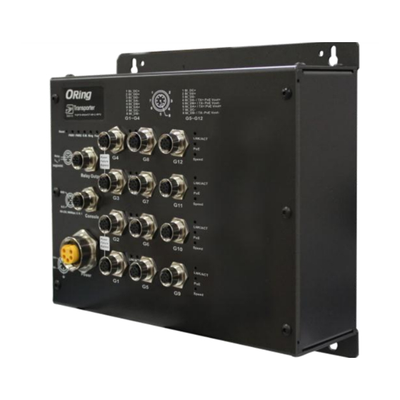
TGPS-9084GT-M12 Series User Manual ardware Overview 2.1 Front Panel The device provides the following ports on the front panel. All connectors are in M12/M23 type to ensure tight, robust connections, as well as reliable operation against environmental disturbances, such as vibration and shock. -
Page 10: Front Panel Led
TGPS-9084GT-M12 Series User Manual 1. Reset button 9. PoE-enabled Gigabit Ethernet ports 2. Power 1 LED 10. Link/ACT LED for non-PoE Gigabit ports 3. Power 2 LED 11. Speed LED for non-PoE Gigabit ports 4. R.M status LED 12. Link/ACT LED for PoE-enabled Gigabit ports 5. -
Page 11: Bypass Technology
(as shown in the figure below). Switches with bypass functions such as the TGPS-9084GT-M12-BP2 provide one or more sets of bypass ports that ensure constant network connectivity during power failure. -
Page 12: Hardware Installation
TGPS-9084GT-M12 Series User Manual ardware Installation 3.1 Wall-mount Installation Wall-mount Measurement (Unit = mm) Follow the steps below to mount the switch to the wall. Step 1: Hold the switch upright against the wall Step 2: Insert two screws through the screw holes located at the top and bottom of the unit and fasten the screw to the wall with a screwdriver. -
Page 13: Wiring
TGPS-9084GT-M12 Series User Manual Instead of screwing the screws in all the way, it is advised to leave a space of about 2mm to allow room for sliding the switch between the wall and the screws. 3.2 Wiring WARNING Do not disconnect modules or wires unless power has been switched off or the area is known to be non-hazardous. -
Page 14: Redundant Power Inputs
TGPS-9084GT-M12 Series User Manual 3.2.3 Redundant Power Inputs The switch provides two sets of power supply on a M23 5-pin connector to enable dual power inputs. Step 1: Insert a power cable to the power connector on the device. Step 2: Rotate the outer ring of the cable connector until a snug fit is achieved. Make sure the connection is tight. - Page 15 TGPS-9084GT-M12 Series User Manual connector M12 A-coding 100BASE-TX Cat. 5 100-ohm UTP UTP 100 m (328 ft) connector Cat. 5/Cat. 5e 100-ohm M12 A-coding 1000BASE-T UTP 100 m (328ft) connector Below is the pin assignment for the Ethernet ports. 10/100/1000Base-T(X) M12 port...
-
Page 16: O-Ring/O-Chain
TGPS-9084GT-M12 Series User Manual TD-(transmit) RD-(receive) RD+(receive) TD+(transmit) Not used Not used Not used Not used RD-(receive) TD-(transmit) Not used Not used Not used Not used 1000Base-T MDI/MDI-X Pin Assignments: Pin Number MDI port MDI-X port BI_DA+ BI_DB+ BI_DA- BI_DB-... - Page 17 TGPS-9084GT-M12 Series User Manual 2. Set one of the connected switches to be the master and make sure the port setting of each connected switch on the management page corresponds to the physical ports connected. For information about the port setting, please refer to 4.1.2 Configurations.
- Page 18 TGPS-9084GT-M12 Series User Manual Dual Homing If you want to connect your ring topology to a RSTP network environment, you can use dual homing. Choose two switches (Switch A & B) from the ring for connecting to the switches in the RSTP network (core switches).
- Page 19 TGPS-9084GT-M12 Series User Manual ORing Industrial Networking Corp...
-
Page 20: Redundancy
4.1 O-Ring 4.1.1 Introduction O-Ring is ORing's proprietary redundant ring technology, with recovery time of less than 30 milliseconds (in full-duplex Gigabit operation) or 10 milliseconds (in full-duplex Fast Ethernet operation) and up to 250 nodes. The ring protocols identify one switch as the master of the network, and then automatically block packets from traveling through any of the network‟s... - Page 21 TGPS-9084GT-M12 Series User Manual Label Description Check to enable O-Ring topology. Redundant Ring Only one ring master is allowed in a ring. However, if more than one switches are set to enable Ring Master, the switch Ring Master with the lowest MAC address will be the active ring master and the others will be backup masters.
-
Page 22: Open-Ring
4.2 OPEN-Ring 4.2.1 Introduction Open-Ring is a technology developed by ORing to enhance ORing switches‟ interoperability with other vendors‟ products. With this technology, you can add any ORing switches to the network based on other ring technologies. 4.2.2 Configurations Label... -
Page 23: O-Chain
Ring Port 4.3 O-Chain 4.3.1 Introduction O-Chain is ORing‟s revolutionary network redundancy technology which enhances network redundancy for any backbone networks, providing ease-of-use and maximum fault-recovery swiftness, flexibility, compatibility, and cost-effectiveness in a set of network redundancy topologies. The self-healing Ethernet technology designed for distributed and complex... -
Page 24: Bypass
TGPS-9084GT-M12 Series User Manual Label Description Enable Check to enable O-Chain function Ring Port The first port connecting to the ring Ring Port The second port connecting to the ring Edge Port An O-Chain topology must begin with edge ports. The ports with a smaller switch MAC address will serve as the backup link and RM LED will light up. -
Page 25: Bypass & Ring Topology
TGPS-9084GT-M12 Series User Manual Figure 2 4.4.2 Bypass & Ring Topology Bypass provides redundancy during device failure and O-Ring provides redundancy when links are broken. Together the two will provide users with dual protection when links and devices are broken. - Page 26 TGPS-9084GT-M12 Series User Manual Fast Ethernet Networks Fiber Networks When a link between two switches fails following the breakdown of the switch, the backup link will be activated. Data will then be transmitted via the backup path (see below). Fast Ethernet Networks...
-
Page 27: Mrp
TGPS-9084GT-M12 Series User Manual Fiber Networks Note: The maximum cable length for copper ports is 100 meters and 20km for fiber ports. When data bypasses the inactive switch(s) to another active switch, the distance between the two active switches must be within the maximum length, otherwise transmission will fail. -
Page 28: Stp/Rstp/Mstp
TGPS-9084GT-M12 Series User Manual set to be Manager, the MRP topology will fail. React on Link Change Faster mode. Enabling this function will cause MRP topology to (Advanced mode) converge more rapidly. This function only can be set in MRP manager switch. - Page 29 TGPS-9084GT-M12 Series User Manual instance. Topology Change Last The time since last Topology Change occurred. Refresh Click to refresh the page immediately. Check this box to enable an automatic refresh of the page at Auto-refresh regular intervals. STP Port Status This page displays the STP port status for the currently selected switch.
- Page 30 TGPS-9084GT-M12 Series User Manual Label Description The switch port number to which the following settings will be Port applied. The number of RSTP configuration BPDUs received/transmitted RSTP on the port number legacy configuration BPDUs received/transmitted on the port The number of (legacy) topology change notification BPDUs...
-
Page 31: Mstp
TGPS-9084GT-M12 Series User Manual ports to forwarding (used in STP compatible mode). The range of valid values is 4 to 30 seconds. The maximum time the information transmitted by the root bridge Max Age is considered valid. The range of valid values is 6 to 40 seconds, and Max Age must be <= (FwdDelay-1)*2. - Page 32 TGPS-9084GT-M12 Series User Manual Label Description Port The switch port number of the corresponding STP CIST (and MSTI) port Configures the path cost incurred by the port. Auto will set the path cost according to the physical link speed by using the 802.1D-recommended values.
- Page 33 TGPS-9084GT-M12 Series User Manual Label Description The name which identifies the VLAN to MSTI mapping. Bridges must share the name and revision (see below), as well as the Configuration Name VLAN-to-MSTI mapping configurations in order to share spanning trees for MSTIs (intra-region). The name should not exceed 32 characters.
-
Page 34: Cist
TGPS-9084GT-M12 Series User Manual Priority This page allows you to examine and change the configurations of current STP MSTI bridge instance priority. Label Description The bridge instance. CIST is the default instance, which is always MSTI active. Indicates bridge priority. The lower the value, the higher the Priority priority. - Page 35 TGPS-9084GT-M12 Series User Manual Label Description The switch port number to which the following settings will be Port applied. STP Enabled Check to enable STP for the port Configures the path cost incurred by the port. Auto will set the path cost according to the physical link speed by using the 802.1D-recommended values.
-
Page 36: Fast Recovery
TGPS-9084GT-M12 Series User Manual can be set by a network administrator to prevent bridges outside a core region of the network from influencing the active spanning tree topology because those bridges are not under the full control of the administrator. This feature is also known as Root Guard. - Page 37 TGPS-9084GT-M12 Series User Manual Label Description Active Activate fast recovery mode port Ports can be set to 12 priorities. Only the port with the highest priority will be the active port. 1st Priority is the highest. Apply Click to activate the configurations.
-
Page 38: Management
TGPS-9084GT-M12 Series User Manual anagement The switch can be controlled via a built-in web server which supports Internet Explorer (Internet Explorer 5.0 or above versions) and other Web browsers such as Chrome. Therefore, you can manage and configure the switch easily and remotely. You can also upgrade firmware via a Web browser. -
Page 39: Basic Settings
TGPS-9084GT-M12 Series User Manual User Name: admin Password: admin After logging in, you will see the information of the switch as below. On the right hand side of the management interface shows links to various settings. Clicking on the links will bring you to individual configuration pages. -
Page 40: Admin & Password
TGPS-9084GT-M12 Series User Manual Label Description An administratively assigned name for the managed node. By convention, this is the node's fully-qualified domain name. A domain name is a text string consisting of alphabets (A-Z, a-z), System Name digits (0-9), and minus sign (-). Space is not allowed to be part of the name. -
Page 41: Authentication Methods
TGPS-9084GT-M12 Series User Manual and only ASCII characters from 32 to 126 are allowed. Confirm New Re-type the new password. Password Save Click to save changes. 5.1.3 Authentication Methods This page allows you to configure how a user is authenticated when he/she logs into the switch via one of the management interfaces. -
Page 42: Ipv6 Settings
TGPS-9084GT-M12 Series User Manual new values will be applied, which will be displayed under Current. Label Description Enable the DHCP client by checking this box. If DHCP fails or the configured IP address is zero, DHCP will retry. If DHCP retry fails, DHCP Client DHCP will stop trying and the configured IP settings will be used. - Page 43 TGPS-9084GT-M12 Series User Manual Label Description Check to enable IPv6 auto-configuration. If the system cannot obtain the stateless address in time, the configured IPv6 settings Auto Configuration will be used. The router may delay responding to a router solicitation for a few seconds; therefore, the total time needed to complete auto-configuration may be much longer.
-
Page 44: Daylight Saving Time
TGPS-9084GT-M12 Series User Manual 5.1.6 Daylight Saving Time Label Description Select an appropriate time zone from the drop down list according Time Zone to the location of the device and then click Save. You can set an acronym for the time zone for identification (up to... - Page 45 TGPS-9084GT-M12 Series User Manual duration will repeat the configuration every year. Select Non-Recurring and the Daylight Saving Time duration will only take effect once. ( Default is Disabled ) Recurring Configurations - Start time settings Label Description Month Select the starting month.
-
Page 46: Https
TGPS-9084GT-M12 Series User Manual Label Description Enter the number of minutes to add during Daylight Saving Time. Offset (Range from 1 to 1440 ) 5.1.7 HTTPS You can configure the HTTPS mode in the following page. Label Description Indicates the selected HTTPS mode. When the current... -
Page 47: Lldp
TGPS-9084GT-M12 Series User Manual Label Description Indicates the selected SSH mode. The modes include: Mode Enabled: enable SSH. Disabled: disable SSH. Save Click to save changes Click to undo any changes made locally and revert to previously Reset saved values 5.1.9 LLDP... - Page 48 TGPS-9084GT-M12 Series User Manual LLDP Neighbor Information This page provides a status overview for all LLDP neighbors. The following table contains information for each port on which an LLDP neighbor is detected. The columns include the following information: Label Description Local Port The port that you use to transmits and receives LLDP frames.
- Page 49 TGPS-9084GT-M12 Series User Manual Global Counters Label Description Neighbor entries Shows the time when the last entry was deleted or added. were last changed at Total Neighbors Shows the number of new entries added since switch reboot Entries Added Total Neighbors...
-
Page 50: Modbus Tcp
TGPS-9084GT-M12 Series User Manual received, or when the entry ages out. Each LLDP frame can contain multiple pieces of information, TLVs Discarded known as TLVs (Type Length Value). If a TLV is malformed, it will be counted and discarded. TLVs Unrecognized The number of well-formed TLVs, but with an unknown type value Org. -
Page 51: Firmware Update
TGPS-9084GT-M12 Series User Manual 5.1.12 Firmware Update This page allows you to update the firmware of the switch. 5.2 DHCP Server The switch provides DHCP server functions. By enabling DHCP, the switch will become a DHCP server and dynamically assigns IP addresses and related IP information to network clients. -
Page 52: Dynamic Client List
TGPS-9084GT-M12 Series User Manual 5.2.2 Dynamic Client List When DHCP server functions are activated, the switch will collect DHCP client information and display in the following table. You can select the entries and add them to a static table by clicking Add to static Table. -
Page 53: Relay Agent
TGPS-9084GT-M12 Series User Manual 5.2.4 Relay Agent DHCP relay is used to forward and transfer DHCP messages between the clients and the server when they are not in the same subnet domain. You can configure the function in this page. - Page 54 TGPS-9084GT-M12 Series User Manual a DHCP client. It only works when DHCP relay mode is enabled. Disabled: disable DHCP relay information Relay Information Indicates the policies to be enforced when receiving DHCP relay Policy information. When DHCP relay information mode is enabled, if the agent receives a DHCP message that already contains relay agent information, it will enforce the policy.
-
Page 55: Port Setting
TGPS-9084GT-M12 Series User Manual Label Description Transmit to Client The number of packets relayed from the server to the client Transmit Error The number of packets with errors when being sent to servers Receive from Client The number of packets received from the server... - Page 56 TGPS-9084GT-M12 Series User Manual Label Description The switch port number to which the following settings will be Port applied. The current link state is shown by different colors. Green indicates Link the link is up and red means the link is down.
-
Page 57: Port Trunk
TGPS-9084GT-M12 Series User Manual 5.3.2 Port Trunk A port trunk is a group of ports that have been grouped together to function as one logical path. This method provides an economical way for you to increase the bandwidth between the switch and another networking device. - Page 58 TGPS-9084GT-M12 Series User Manual Label Description Group ID Indicates the ID of each aggregation group. Normal means no aggregation. Only one group ID is valid per port. Port Members Lists each switch port for each group ID. Select a radio button to include a port in an aggregation, or clear the radio button to remove the port from the aggregation.
- Page 59 TGPS-9084GT-M12 Series User Manual LACP Enabled Lists each switch port for each group ID. Check to include a port in an aggregation, or clear the box to remove the port from the aggregation. By default, no ports belong to any aggregation group. Only full duplex ports can join an aggregation and the ports must be in the same speed in each group.
- Page 60 TGPS-9084GT-M12 Series User Manual LACP Status This page provides an overview of the LACP status for all ports. Label Description Port Switch port number LACP Yes means LACP is enabled and the port link is up. No means LACP is not enabled or the port link is down. Backup means the port cannot join in the aggregation group unless other ports are removed.
-
Page 61: Loop Gourd
TGPS-9084GT-M12 Series User Manual LACP Statistics This page provides an overview of the LACP statistics for all ports. Label Description Port Switch port number LACP Transmitted The number of LACP frames sent from each port LACP Received The number of LACP frames received at each port... - Page 62 TGPS-9084GT-M12 Series User Manual Label Description Enable Loop Protection Activate loop protection functions (as a whole) Transmission Time The interval between each loop protection PDU sent on each port. The valid value is 1 to 10 seconds. Shutdown Time The period (in seconds) for which a port will be kept disabled when a loop is detected (shutting down the port).
-
Page 63: Vlan
TGPS-9084GT-M12 Series User Manual 5.4 VLAN 5.4.1 VLAN Membership A VLAN is a group of end devices with a common set of requirements, independent of physical location. With the same attributes as a physical LAN, VLANs enable you to group end devices even if they are not located physically on the same LAN segment. -
Page 64: Port Configurations
TGPS-9084GT-M12 Series User Manual 5.4.2 Port Configurations With port-based VLANs, the ports of a switch are simply assigned to VLANs, with no extra criteria. All devices connected to a given port automatically become members of the VLAN to which that port was assigned. In effect, this just divides a switch up into a set of independent sub-switches. - Page 65 TGPS-9084GT-M12 Series User Manual VLAN tag, and the tag is removed. S-port: the EtherType of all received frames is changed to 0x88a8 to indicate that double-tagged frames are being forwarded across the switch. The switch will pass these frames on to the VLAN indicated in the outer tag.
- Page 66 TGPS-9084GT-M12 Series User Manual VLAN ID will be inserted in the frame. Configures the VLAN identifier for the port. The allowed range of the values is 1 through 4095. The default value is 1. Port VLAN ID Note: The port must be a member of the same VLAN as the port VLAN ID.
- Page 67 TGPS-9084GT-M12 Series User Manual 2. If the TPID of tagged frame is not 0x88A8 (ex. 0x8100), it will be discarded. S-custom-port When the port receives untagged frames, an The TPID of a frame untagged frame obtains a tag (based on PVID) transmitted by and is forwarded.
- Page 68 TGPS-9084GT-M12 Series User Manual ORing Industrial Networking Corp...
- Page 69 TGPS-9084GT-M12 Series User Manual Examples of VLAN Settings VLAN Access Mode: Switch Port 7 is VLAN Access mode = Untagged 20 Port 8 is VLAN Access mode = Untagged 10 Below are the switch settings. ORing Industrial Networking Corp...
- Page 70 TGPS-9084GT-M12 Series User Manual VLAN 1Q Trunk Mode: Switch Port 1 = VLAN 1Qtrunk mode = tagged 10, 20 Port 2 = VLAN 1Qtrunk mode = tagged 10, 20 Below are the switch settings. ORing Industrial Networking Corp...
- Page 71 TGPS-9084GT-M12 Series User Manual VLAN Hybrid Mode: Port 1 VLAN Hybrid mode = untagged 10 Tagged 10, 20 Below are the switch settings. ORing Industrial Networking Corp...
- Page 72 TGPS-9084GT-M12 Series User Manual VLAN QinQ Mode: VLAN QinQ mode is usually adopted when there are unknown VLANs, as shown in the figure below VLAN “X” = Unknown VLAN 9000 Series Port 1 VLAN Settings: VLAN ID Settings When setting the management VLAN, only the same VLAN ID port can be used to control the switch.
-
Page 73: Private Vlan
TGPS-9084GT-M12 Series User Manual 9000 Series VLAN Settings: 5.4.3 Private VLAN A private VLAN contains switch ports that can only communicate with a given "uplink". The restricted ports are called private ports. Each private VLAN typically contains many private ports and a single uplink. The switch forwards all frames received on a private port out the uplink port, regardless of VLAN ID or destination MAC address. -
Page 74: Snmp
TGPS-9084GT-M12 Series User Manual VLAN. To remove or exclude the port from the private VLAN, make sure the box is unchecked. By default, no ports are members, and all boxes are unchecked. Click Add new Private VLAN to add a new private VLAN ID. An empty row is added to the table, and the private VLAN can be configured as needed. -
Page 75: Snmp System Configurations
TGPS-9084GT-M12 Series User Manual networked devices. In an event-triggered situation, traps and notifications will be sent to administrators. 5.5.1 SNMP System Configurations Label Description Indicates existing SNMP mode. Possible modes include: Mode Enabled: enable SNMP mode Disabled: disable SNMP mode Indicates the supported SNMP version. - Page 76 TGPS-9084GT-M12 Series User Manual Label Description Indicates existing SNMP trap mode. Possible modes include: Trap Mode Enabled: enable SNMP trap mode Disabled: disable SNMP trap mode Indicates the supported SNMP trap version. Possible versions include: Trap Version SNMP v1: supports SNMP trap version 1...
-
Page 77: Snmp Community Configurations
TGPS-9084GT-M12 Series User Manual Disabled: disable SNMP trap authentication failure Indicates the SNMP trap link-up and link-down mode. Possible Trap Link-up and modes include: Link-down Enabled: enable SNMP trap link-up and link-down mode Disabled: disable SNMP trap link-up and link-down mode Indicates the SNMP trap inform mode. -
Page 78: Snmp User Configurations
TGPS-9084GT-M12 Series User Manual 5.5.3 SNMP User Configurations Each SNMP user has a specified username, a group to which the user belongs, authentication password, authentication protocol, privacy protocol, and privacy password. When you create a user, you must associate it with an SNMP group. The user then inherits the security model of the group. -
Page 79: Snmp Group Configurations
TGPS-9084GT-M12 Series User Manual Indicates the authentication protocol that this entry should belong to. Possible authentication protocols include: None: no authentication protocol MD5: an optional flag to indicate that this user is using MD5 Authentication authentication protocol Protocol SHA: an optional flag to indicate that this user is using SHA... -
Page 80: Snmp View Configurations
TGPS-9084GT-M12 Series User Manual Label Description Delete Check to delete the entry. It will be deleted during the next save. Indicates the security model that this entry should belong to. Possible security models included: Security Model v1: Reserved for SNMPv1. -
Page 81: Snmp Access Configurations
TGPS-9084GT-M12 Series User Manual Delete Check to delete the entry. It will be deleted during the next save. A string identifying the view name that this entry should belong to. View Name The allowed string length is 1 to 32, and only ASCII characters from 33 to 126 are allowed. -
Page 82: Traffic Prioritization
TGPS-9084GT-M12 Series User Manual Indicates the security model that this entry should belong to. Possible security models include: Security Level NoAuth, NoPriv: no authentication and no privacy Auth, NoPriv: Authentication and no privacy Auth, Priv: Authentication and privacy The name of the MIB view defining the MIB objects for which this Read View Name request may request the current values. -
Page 83: Port Classification
TGPS-9084GT-M12 Series User Manual Status Enables or disables the given frame type The rate is packet per second (pps), configure the rate as 1K, 2K, Rate 4K, 8K, 16K, 32K, 64K, 128K, 256K, 512K, or 1024K. The 1 kpps is actually 1002.1 pps. - Page 84 TGPS-9084GT-M12 Series User Manual PCP value: 0 1 2 3 4 5 6 7 QoS class: 1 0 2 3 4 5 6 7 If the port is VLAN aware, the frame is tagged, and Tag Class is enabled, then the frame is classified to a QoS class that is mapped from the PCP and DEI value in the tag.
-
Page 85: Port Tag Remaking
TGPS-9084GT-M12 Series User Manual classified to the default QoS class and DP level. DSCP Based Click to enable DSCP-based QoS Ingress Port Classification 5.6.3 Port Tag Remaking You can set QoS egress queues on a port such as classifying data and marking it according to its priority and the policies. - Page 86 TGPS-9084GT-M12 Series User Manual Label Description Shows the list of ports for which you can configure DSCP Ingress Port and Egress settings. In Ingress settings you can change ingress translation and classification settings for individual ports. There are two configuration parameters available in Ingress:...
-
Page 87: Policing
TGPS-9084GT-M12 Series User Manual remapped DSCP value is always taken from the 'DSCP Translation->Egress Remap DP0' table. Remap DP Aware: DSCP from the analyzer is remapped and the frame is remarked with a remapped DSCP value. Depending on the DP level of the frame, the remapped DSCP value is either taken from the 'DSCP Translation->Egress Remap DP0' table or... -
Page 88: Scheduling And Shaping
TGPS-9084GT-M12 Series User Manual fps, and is restricted to 1 to 3300 when the Unit is Mbps or kfps. Configures the unit of measurement for each policer rate as kbps, Unti Mbps, fps, or kfps. The default value is kbps. - Page 89 TGPS-9084GT-M12 Series User Manual always some content in the highest priority queue, then the other packets in the rest of queues will not be sent until the highest priority queue is empty. The SP algorithm is preferred when the received packets contain high priority data, such as voice and video.
- Page 90 TGPS-9084GT-M12 Series User Manual Excess Port Shaper Enable Check to enable port shaper for individual switch ports Configures the rate of each port shaper. The default value is 500 Port Shaper Rate This value is restricted to 100 to 1000000 when the Unit is kbps, and it is restricted to 1 to 3300 when the Unit is Mbps.
-
Page 91: Port Scheduler
TGPS-9084GT-M12 Series User Manual Label Description Scheduler Mode Two scheduling modes are available: Strict Priority or Weighted Queue Shaper Check to enable queue shaper for individual switch ports Enable Configures the rate of each queue shaper. The default value is Queue Shaper Rate 500. -
Page 92: Port Shaping
TGPS-9084GT-M12 Series User Manual applied. Click on the port number to configure the schedulers Mode Shows the scheduling mode for this port Shows the weight for this queue and port 5.6.9 Port Shaping Port shaping enables you to limit traffic on a port, thereby controlling the amount of traffic passing through the port. -
Page 93: Dscp Translation
TGPS-9084GT-M12 Series User Manual Label Description DSCP Maximum number of supported DSCP values is 64 Check to trust a specific DSCP value. Only frames with trusted DSCP values are mapped to a specific QoS class and drop Trust precedence level. Frames with untrusted DSCP values are treated as a non-IP frame. -
Page 94: Dscp Classification
TGPS-9084GT-M12 Series User Manual QoS Port DSCP Configuration table. Configurable engress parameters include; Remap DP0: R e-maps DP0 field to selected DSCP value. DP0 indicates a drop precedence with a low priority. You can select the DSCP value from a selected menu to which you want to remap. - Page 95 TGPS-9084GT-M12 Series User Manual Label Description Port Members Check to include the port in the QCL entry. By default, all ports are included. Key Parameters Key configurations include: Tag: value of tag, can be Any, Untag or Tag. VID: valid value of VLAN ID from 1 to 4095 Any: can be a specific value or a range of VIDs.
- Page 96 TGPS-9084GT-M12 Series User Manual excluding 0x800(IPv4) and 0x86DD(IPv6). The default value is Any. SSAP Address: valid SSAP (Source Service Access Point) values can range from 0x00 to 0xFF or Any. The default value is Any. DSAP Address: valid DSAP (Destination Service Access Point) values can range from 0x00 to 0xFF or Any.
-
Page 97: Qos Counters
TGPS-9084GT-M12 Series User Manual Valid DSCP value can be (0-63, BE, CS1-CS7, EF or AF11-AF43) or Default. Default means that the default classified value is not modified by this QCE. 5.6.14 QoS Counters This page shows information on the number of packets sent and received at each queue. -
Page 98: Multicast
TGPS-9084GT-M12 Series User Manual Label Description User Indicates the QCL user QCE# Indicates the index of QCE Indicates the type of frame to look for incoming frames. Possible frame types are: Any: the QCE will match all frame type. Ethernet: Only Ethernet frames (with Ether Type 0x600-0xFFFF) Frame Type are allowed. -
Page 99: Vlan Configurations Of Igmp Snooping
TGPS-9084GT-M12 Series User Manual This page allows you to set up IGMP snooping configurations. Label Description Snooping Enabled Check to enable global IGMP snooping Unregistered IPMCv4Flooding Check to enable unregistered IPMC traffic flooding enabled Specifies which ports act as router ports. A router port is a port on the... -
Page 100: Igmp Snooping Status
TGPS-9084GT-M12 Series User Manual installs hardware resources, so that subsequent data packets can be switched to desired ports in hardware without going to the CPU. Each page shows up to 99 entries from the VLAN table, depending on the value in the Entries Per Page field. -
Page 101: Groups Information Of Igmp Snooping
TGPS-9084GT-M12 Series User Manual Label Description VLAN ID The VLAN ID of the entry Querier Version Active Querier version Host Version Active Host version Querier Status Shows the Querier status as ACTIVE or IDLE Querier Receive The number of transmitted Querier... -
Page 102: Security
TGPS-9084GT-M12 Series User Manual Label Description VLAN ID The VLAN ID of the group Groups The group address of the group displayed Port Members Ports under this group 5.8 Security 5.8.1 Remote Control Security Configurations Remote Control Security allows you to limit remote access to the management interface. -
Page 103: Device Binding
Check to delete entries 5.8.2 Device Binding Device binding is ORing's proprietary technology which binds the IP/MAC address of a device with a specified Ethernet port. If the IP/MAC address of the device connected to the Ethernet port does not conform to the binding requirements, the device will be locked for security concerns. - Page 104 TGPS-9084GT-M12 Series User Manual Indicates stream check status. Possible statuses are: Stream Check ---: disable Status Normal: the stream is normal. Low: the stream is getting low. DDoS Prevention Check to enable DDOS prevention. When enabled, the switch will Acton monitor the device against DDOS attacks.
- Page 105 TGPS-9084GT-M12 Series User Manual Alive Check Alive Check monitors the real-time status of the device connected to the port. live-checking packets will be sent to the device to probe if the device is running. If the switch receives no response from the device, actions will be taken according to your configurations.
- Page 106 TGPS-9084GT-M12 Series User Manual Label Description Mode Enables or disables DDOS prevention of the port Indicates the level of DDOS detection. Possible levels are: Low: low sensibility Sensibility Normal: normal sensibility Medium: medium sensibility High: high sensibility Indicates the types of DDoS attack packets to be monitored. Possible...
- Page 107 TGPS-9084GT-M12 Series User Manual the event Blocking: blocks and logs the event Shunt Down the Port: shuts down the port (No Link) and logs the event Only Log it: simply logs the event Reboot Device: if PoE is supported, the device can be rebooted.
-
Page 108: Acl
TGPS-9084GT-M12 Series User Manual Network Video Recorder Indicates location information of the device. The information can be Location Address used for Google Mapping. Description Device descriptions Stream Check Stream check monitors the consistency of real-time network traffic from the device bound with the port. - Page 109 TGPS-9084GT-M12 Series User Manual Port Configuration Label Description Port The switch port number to which the following settings will be applied Select to apply a policy to the port. The allowed values are 1 to 8. Policy ID The default value is 1.
- Page 110 TGPS-9084GT-M12 Series User Manual Label Description Rate Limiter ID The rate limiter ID for the settings contained in the same row. The rate unit is packet per second (pps), which can be configured as 1, 2, 4, 8, 16, 32, 64, 128, 256, 512, 1K, 2K, 4K, 8K, 16K, 32K, 64K, Rate 128K, 256K, 512K, or 1024K.
- Page 111 TGPS-9084GT-M12 Series User Manual Any: the ACE applies to any port Port n: the ACE applies to this port number, where n is the number of the switch port. Policy n: the ACE applies to this policy number, where n can range from 1 to 8.
- Page 112 TGPS-9084GT-M12 Series User Manual Label Description (Only displayed when the frame type is Ethernet Type or ARP.) Specifies the source MAC filter for the ACE. SMAC Filter Any: no SMAC filter is specified (SMAC filter status is "don't-care"). Specific: if you want to filter a specific source MAC address with the ACE, choose this value.
- Page 113 TGPS-9084GT-M12 Series User Manual Label Description Specifies the VLAN ID filter for the ACE Any: no VLAN ID filter is specified (VLAN ID filter status is VLAN ID Filter "don't-care"). Specific: if you want to filter a specific VLAN ID with the ACE, choose this value.
- Page 114 TGPS-9084GT-M12 Series User Manual Label Description Specifies the IP protocol filter for the ACE Any: no IP protocol filter is specified ("don't-care"). Specific: if you want to filter a specific IP protocol filter with the ACE, choose this value. A field for entering an IP protocol filter appears.
- Page 115 TGPS-9084GT-M12 Series User Manual Specifies the source IP filter for this ACE Any: no source IP filter is specified (Source IP filter is "don't-care"). Host: source IP filter is set to Host. Specify the source IP address in SIP Filter the SIP Address field that appears.
- Page 116 TGPS-9084GT-M12 Series User Manual ARP: frame must have ARP/RARP opcode set to ARP RARP: frame must have ARP/RARP opcode set to RARP. Other: frame has unknown ARP/RARP Opcode flag. Specifies the available ARP/RARP opcode (OP) flag for the ACE Any: no ARP/RARP OP flag is specified (OP is "don't-care").
- Page 117 TGPS-9084GT-M12 Series User Manual 0: RARP frames where THA is not equal to the SMAC address 1: RARP frames where THA is equal to the SMAC address Any: any value is allowed ("don't-care") Specifies whether frames will meet the action according to their ARP/RARP hardware address length (HLN) and protocol address length (PLN) settings.
- Page 118 TGPS-9084GT-M12 Series User Manual Label Description Specifies the ICMP filter for the ACE Any: no ICMP filter is specified (ICMP filter status is "don't-care"). ICMP Type Filter Specific: if you want to filter a specific ICMP filter with the ACE, you can enter a specific ICMP value.
- Page 119 TGPS-9084GT-M12 Series User Manual entering a TCP/UDP source value appears. Range: if you want to filter a specific TCP/UDP source range filter with the ACE, you can enter a specific TCP/UDP source range. A field for entering a TCP/UDP source value appears.
-
Page 120: Authentication, Authorization, And Accounting
TGPS-9084GT-M12 Series User Manual the ACE 0: TCP frames where the SYN field is set must not be able to match this entry. 1: TCP frames where the SYN field is set must be able to match this entry. Any: any value is allowed ("don't-care"). -
Page 121: Radius
TGPS-9084GT-M12 Series User Manual Label Description The timeout, which can be set to a number between 3 and 3600 seconds, is the maximum time to wait for a reply from a server. If the server does not reply within this time frame, we will consider it to be dead and continue with the next enabled server (if any). - Page 122 TGPS-9084GT-M12 Series User Manual forward accounting information to the RADIUS server to document the transaction; the RADIUS server may store or forward this information as needed to support billing for the services provided. Label Description RADIUS authentication server number for which the configuration below applies.
- Page 123 TGPS-9084GT-M12 Series User Manual Label Description The RADIUS accounting server number for which the configuration below applies. Enabled Check to enable the RADIUS accounting server The IP address or hostname of the RADIUS accounting server. IP IP Address address is expressed in dotted decimal notation.
- Page 124 TGPS-9084GT-M12 Series User Manual and running. Ready: the server is enabled, IP communications are built, and the RADIUS module is ready to accept access attempts. Dead (X seconds left): access attempts are made to this server, but it does not reply within the configured timeout. The server has temporarily been disabled, but will be re-enabled when the dead-time expires.
- Page 125 TGPS-9084GT-M12 Series User Manual Authentication and Accounting Server Statistics This page shows the access statistics of the authentication and accounting servers. Use the server drop-down list to switch between the backend servers to show related details. Label Description RADIUS authentication server packet counters. There are seven „receive‟...
- Page 126 TGPS-9084GT-M12 Series User Manual This section contains information about the state of the server and the latest round-trip time. Other Info Label Description RADIUS accounting server packet counters. There are five „receive‟ „transmit‟ four counters. Packet Counters ORing Industrial Networking Corp...
-
Page 127: Nas (802.1X)
TGPS-9084GT-M12 Series User Manual This section contains information about the state of the server and the latest round-trip time. Other Info 5.8.6 NAS (802.1x) A NAS (Network Access Server) is an access gateway between an external communications network and an internal network. For example, when the user dials into the ISP, he/she will be given access to the Internet after being authorized by the access server. - Page 128 TGPS-9084GT-M12 Series User Manual into the relevant type (EAPOL or RADIUS) and forwards it. When authentication is complete, the RADIUS server sends a special packet containing a success or failure indication. Besides forwarding the result to the supplicant, the switch uses it to open up or block traffic on the switch port connected to the supplicant.
- Page 129 TGPS-9084GT-M12 Series User Manual Label Description Indicates if 802.1X and MAC-based authentication is globally Mode enabled or disabled on the switch. If globally disabled, all ports are allowed to forward frames. If checked, clients are reauthenticated after the interval specified Reauthentication Period.
- Page 130 TGPS-9084GT-M12 Series User Manual Valid range of the value is 1 to 65535 seconds. This has no effect for MAC-based ports. This setting applies to the following modes, i.e. modes using the Port Security functionality to secure MAC addresses: MAC-Based Auth.:...
- Page 131 TGPS-9084GT-M12 Series User Manual the port link is up, and any client on the port will be disallowed network access. Port-based 802.1X In an 802.1X network environment, the user is called the supplicant, the switch is the authenticator, and the RADIUS server is the authentication server.
- Page 132 TGPS-9084GT-M12 Series User Manual loop forever. Therefore, the server timeout should be smaller than the supplicant's EAPOL Start frame retransmission rate. a. Single 802.1X In port-based 802.1X authentication, once a supplicant is successfully authenticated on a port, the whole port is opened for network traffic.
- Page 133 TGPS-9084GT-M12 Series User Manual address as the destination MAC address for EAPOL frames sent from the switch to the supplicant, since that would cause all supplicants attached to the port to reply to requests sent from the switch. Instead, the switch uses the supplicant's MAC address, which is obtained from the first EAPOL Start or EAPOL Response Identity frame sent by the supplicant.
- Page 134 TGPS-9084GT-M12 Series User Manual supplicant software authenticate. advantage MAC-based authentication over 802.1X-based authentication is that the clients do not need special supplicant software to authenticate. The disadvantage is that MAC addresses can be spoofed by malicious users - equipment whose MAC address is a valid RADIUS user can be used by anyone.
- Page 135 TGPS-9084GT-M12 Series User Manual NAS Status This page shows the information on current NAS port statuses. Label Description The switch port number. Click to navigate to detailed 802.1X Port statistics of each port. The port‟s current administrative state. Refer to NAS Admin State Admin State for more details regarding each value.
- Page 136 TGPS-9084GT-M12 Series User Manual Label Description Admin State The port's current administrative state. Refer to NAS Admin State for more details regarding each value. Port State The current state of the port. Refer to NAS Port State for more details regarding each value.
-
Page 137: Alerts
TGPS-9084GT-M12 Series User Manual Information about the last supplicant/client that attempts to authenticate. This information available for following administrative states: • 802.1X • MAC-based Auth. Last Supplicant/Client Info 5.9 Alerts 5.9.1 Fault Alarm When any selected fault event happens, the Fault LED on the switch panel will light up and the electric relay will signal at the same time. -
Page 138: System Warning
TGPS-9084GT-M12 Series User Manual 5.9.2 System Warning SYSLOG Setting SYSLOG is a protocol that allows a device to send event notification messages across IP networks to event message collectors. It permits separation of the software that generates messages from the system that stores them and the software that reports and analyzes them. - Page 139 TGPS-9084GT-M12 Series User Manual always be sent even if the syslog server does not exist. Possible modes are: Enabled: enable server mode Disabled: disable server mode SYSLOG Server IP Address Indicates the IPv4 host address of syslog server. If the switch provides DNS functions, it also can be a host name.
- Page 140 TGPS-9084GT-M12 Series User Manual Help Shows help file Event Selection The device supports both SYSLOG and SMTP alerts. Check the corresponding box to enable the system event warning method you want. Please note that the checkboxes will gray out if SYSLOG or SMTP is disabled.
-
Page 141: Monitor And Diag
TGPS-9084GT-M12 Series User Manual 5.10 Monitor and Diag 5.10.1 MAC Table A MAC address tablet is a table in a network switch that maps MAC addresses to ports. The switch uses the table to determine which port the incoming packet should be forwarded to. - Page 142 TGPS-9084GT-M12 Series User Manual the address does not exist in the table by examining the source address of each packet received on a port. This is called learning. It allows the MAC table to expand dynamically. If the learning mode for a given port is grayed out, it means another module is in control of the mode, and thus the user cannot change the configurations.
- Page 143 TGPS-9084GT-M12 Series User Manual Label Description Delete Check to delete an entry. It will be deleted during the next save. VLAN ID The VLAN ID for the entry MAC Address The MAC address for the entry Checkmarks indicate which ports are members of the entry.
-
Page 144: Port Statistics
TGPS-9084GT-M12 Series User Manual MAC address The MAC address of the entry VLAN The VLAN ID of the entry Port Members The ports that are members of the entry. 5.10.2 Port Statistics Traffic Overview This page provides an overview of general traffic statistics for all switch ports. - Page 145 TGPS-9084GT-M12 Series User Manual Label Description Rx and Tx Packets The number of received and transmitted (good and bad) packets The number of received and transmitted (good and bad) bytes, Rx and Tx Octets including FCS, except framing bits The number of received and transmitted (good and bad) unicast...
-
Page 146: Port Mirroring
TGPS-9084GT-M12 Series User Manual CRC/Alignment Rx Undersize The number of short frames received with a valid CRC Rx Oversize The number of long frames received with a valid CRC Rx Fragments The number of short frames received with an invalid CRC... -
Page 147: System Log Information
TGPS-9084GT-M12 Series User Manual Drop-down list for selecting a mirror mode. Rx only: only frames received on this port are mirrored to the mirror port. Frames transmitted are not mirrored. Tx only: only frames transmitted from this port are mirrored to the mirror port. -
Page 148: Cable Diagnostics
TGPS-9084GT-M12 Series User Manual Refresh Updates system log entries, starting from the current entry ID Clear Flushes all system log entries |<< Updates system log entries, starting from the first available entry ID Updates system log entries, ending at the last entry currently <<... -
Page 149: Sfp Monitor
TGPS-9084GT-M12 Series User Manual Pair: the status of the cable pair Length: the length (in meters) of the cable pair 5.10.6 SFP Monitor SFP modules with DDM (Digital Diagnostic Monitoring) function can measure the temperature of the apparatus, helping you monitor the status of connection and detect errors immediately. -
Page 150: Synchronization
TGPS-9084GT-M12 Series User Manual After you press Start, five ICMP packets will be transmitted, and the sequence number and roundtrip time will be displayed upon reception of a reply. The page refreshes automatically until responses to all packets are received, or until a timeout occurs PING6 server ::10.10.132.20... - Page 151 TGPS-9084GT-M12 Series User Manual network. On a local area network, it achieves clock accuracy in the sub-microsecond range, making it suitable for measurement and control systems. Label Description One_pps_mode The box allows you to select One_pps_mode configurations. The following values are possible:...
- Page 152 TGPS-9084GT-M12 Series User Manual Label Description Delete Check this box and click Save to delete the clock instance Clock Instance Indicates the instance of a particular clock instance [0..3] Click on the clock instance number to edit the clock details Device Type Indicates the type of the clock instance.
-
Page 153: Poe
TGPS-9084GT-M12 Series User Manual 5.12 PoE 5.12.1 Configurations PoE (Power Over Ethernet) is a technology that transmits electrical power to devices such as IP telephones, wireless LAN access points, and IP cameras over standard Ethernet cables. The ability is very useful in places where power supply is difficult or expensive deploy. - Page 154 TGPS-9084GT-M12 Series User Manual will gray out. In all of the abovementioned modes, if a port uses more power than the reserved power for the port, the port is shut down. Power Management There are two modes available when configuring when to shut...
-
Page 155: Status
TGPS-9084GT-M12 Series User Manual highest port number. Maximum Power Indicates the maximum power in watts that can be delivered to a remote device (the maximum allowed value is 30 W). 5.12.2 Status This page allows you to examine the current status for all PoE ports. -
Page 156: Poe Schedule
TGPS-9084GT-M12 Series User Manual PoE turned OFF: power budget exceeded. The total requested or used power by the power devices exceeds the maximum power the power supply can deliver, and port(s) with the lowest priority will be powered down. No PD detected: no power devices detected on the port PoE turned OFF: power devices overload. -
Page 157: Troubleshooting
TGPS-9084GT-M12 Series User Manual Label Description Enables or disables Ping check function Ping Check Port Assigns a port for which you want to control its PoE function Ping IP Address Input the IP address for the port Interval Time Specify a Ping interval (10 sec~120 sec) -
Page 158: System Reboot
TGPS-9084GT-M12 Series User Manual Label Description Click to reset the configuration to factory defaults Click to return to the Port State page without resetting 5.13.2 System Reboot You can reset the stack switch on this page. After reset, the system will boot normally as if you... -
Page 159: Command Line Management
TGPS-9084GT-M12 Series User Manual ommand Line Management Besides Web-based management, the device also supports CLI management. You can use console or telnet to manage the switch by CLI. CLI Management by RS-232 Serial Console (115200, 8, none, 1, none) Before configuring RS-232 serial console, connect the RS-232 port of the switch to your PC Com port using a RJ45 to DB9-F cable. - Page 160 TGPS-9084GT-M12 Series User Manual Step 3. Select a COM port in the drop-down list. Step 4. A pop-up window that indicates COM port properties appears, including bits per second, data bits, parity, stop bits, and flow control. ORing Industrial Networking Corp...
- Page 161 TGPS-9084GT-M12 Series User Manual Step 5. The console login screen will appear. Use the keyboard to enter the Username and Password (same as the password for Web browsers), then press Enter. CLI Management by Telnet You can can use TELNETto configure the switch. The default values are:...
- Page 162 TGPS-9084GT-M12 Series User Manual IP Address: 192.168.10.1 Subnet Mask: 255.255.255.0 Default Gateway: 192.168.10.254 User Name: admin Password: admin Follow the steps below to access console via Telnet. Step 1. Telnet to the IP address of the switch from the Run window by inputting commands (or from the MS-DOS prompt) as below.
- Page 163 TGPS-9084GT-M12 Series User Manual Commander Groups ORing Industrial Networking Corp...
- Page 164 TGPS-9084GT-M12 Series User Manual System Configuration [all] [<port_list>] Reboot Restore Default [keep_ip] Contact [<contact>] Name [<name>] Location [<location>] System> Description [<description>] Password <password> Username [<username>] Timezone [<offset>] Log [<log_id>] [all|info|warning|error] [clear] Configuration DHCP [enable|disable] IP> Setup [<ip_addr>] [<ip_mask>] [<ip_router>] [<vid>] Ping <ip_addr_string>...
- Page 165 TGPS-9084GT-M12 Series User Manual Lookup <mac_addr> [<vid>] Agetime [<age_time>] Learning [<port_list>] [auto|disable|secure] Dump [<mac_max>] [<mac_addr>] [<vid>] Statistics [<port_list>] Flush VLAN Configuration [<port_list>] PVID [<port_list>] [<vid>|none] FrameType [<port_list>] [all|tagged|untagged] IngressFilter [<port_list>] [enable|disable] tx_tag [<port_list>] [untag_pvid|untag_all|tag_all] PortType [<port_list>] [unaware|c-port|s-port|s-custom-port] EtypeCustomSport [<etype>] Add <vid>|<name> [<ports_list>] VLAN>...
- Page 166 TGPS-9084GT-M12 Series User Manual Authentication, Authorization and Accounting setting Security Switch Password <password> Auth Authentication Secure Shell Security/switch> HTTPS Hypertext Transfer Protocol over Secure Socket Layer RMON Remote Network Monitoring Security Switch Authentication Configuration Security/switch/auth> Method [console|telnet|ssh|web] [none|local|radius] [enable|disable] Security Switch SSH Configuration Security/switch/ssh>...
- Page 167 TGPS-9084GT-M12 Series User Manual Security Network Psec Port Security Status Network Access Server (IEEE 802.1X) Security/Network> Access Control List DHCP Dynamic Host Configuration Protocol Security Network Psec Switch [<port_list>] Security/Network/Psec> Port [<port_list>] Security Network NAS Configuration [<port_list>] Mode [enable|disable] State [<port_list>] [auto|authorized|unauthorized|macbased] Reauthentication [enable|disable] ReauthPeriod [<reauth_period>]...
- Page 168 TGPS-9084GT-M12 Series User Manual [<ip_flags>]) | (udp [<sip>] [<dip>] [<sport>] [<dport>] [<ip_flags>]) | (tcp [<sip>] [<dip>] [<sport>] [<dport>] [<ip_flags>] [<tcp_flags>])] [permit|deny] [<rate_limiter>] [<port_redirect>] [<mirror>] [<logging>][<shutdown>] Delete <ace_id> Lookup [<ace_id>] Clear Status [combined|static|loop_protect|dhcp|ptp|ipmc|conflicts] Port State [<port_list>] [enable|disable] Security Network DHCP Configuration Mode [enable|disable] Server [<ip_addr>]...
- Page 169 TGPS-9084GT-M12 Series User Manual MaxAge [<max_age>] FwdDelay [<delay>] bpduFilter [enable|disable] bpduGuard [enable|disable] recovery [<timeout>] CName [<config-name>] [<integer>] Status [<msti>] [<port_list>] Msti Priority [<msti>] [<priority>] Msti Map [<msti>] [clear] Msti Add <msti> <vid> Port Configuration [<port_list>] Port Mode [<port_list>] [enable|disable] Port Edge [<port_list>] [enable|disable] Port AutoEdge [<port_list>] [enable|disable]...
- Page 170 TGPS-9084GT-M12 Series User Manual Role [<port_list>] [active|passive] Status [<port_list>] Statistics [<port_list>] [clear] LLDP Configuration [<port_list>] Mode [<port_list>] [enable|disable] LLDP> Statistics [<port_list>] [clear] Info [<port_list>] Configuration [<port_list>] Mode [<port_list>] [disabled|poe|poe+] Priority [<port_list>] [low|high|critical] PoE> Mgmt_mode [class_con|class_res|al_con|al_res|lldp_res|lldp_con] Maximum_Power [<port_list>] [<port_power>] Status Primary_Supply [<supply_power>] DSCP Map [<dscp_list>] [<class>] [<dpl>]...
- Page 171 TGPS-9084GT-M12 Series User Manual (ipv4 [<protocol>] [<sip>] [<dscp>] [<fragment>] [<sport>] [<dport>]) (ipv6 [<protocol>] [<sip_v6>] [<dscp>] [<sport>] [<dport>])] [<class>] [<dp>] [<classified_dscp>] QCL Delete <qce_id> QCL Lookup [<qce_id>] QCL Status [combined|static|conflicts] QCL Refresh Mirror Configuration [<port_list>] Mirror> Port [<port>|disable] Mode [<port_list>] [enable|disable|rx|tx] Dot1x Configuration [<port_list>]...
- Page 172 TGPS-9084GT-M12 Series User Manual Status [<vid>] Configuration [<port_list>] Action [<port_list>] [permit|deny] [<rate_limiter>] [<port_copy>] [<logging>] [<shutdown>] Policy [<port_list>] [<policy>] Rate [<rate_limiter_list>] [<packet_rate>] Add [<ace_id>] [<ace_id_next>] [switch | (port <port>) | (policy <policy>)] [<vid>] [<tag_prio>] [<dmac_type>] [(etype [<etype>] [<smac>] [<dmac>]) | ACL>...
- Page 173 TGPS-9084GT-M12 Series User Manual Trap Probe Security Engine ID [enable|disable] Trap Security Engine ID [<engineid>] Trap Security Name [<security_name>] Engine ID [<engineid>] Community Add <community> [<ip_addr>] [<ip_mask>] Community Delete <index> Community Lookup [<index>] User Add <engineid> <user_name> [MD5|SHA] [<auth_password>] [DES] [<priv_password>]...
- Page 174 TGPS-9084GT-M12 Series User Manual ParentDS <clockinst> Timingproperties <clockinst> [<utcoffset>] [<valid>] [<leap59>] [<leap61>] [<timetrac>] [<freqtrac>] [<ptptimescale>] [<timesource>] PTP PortDataSet <clockinst> [<port_list>] [<announceintv>] [<announceto>] [<syncintv>] [<delaymech>] [<minpdelayreqintv>] [<delayasymmetry>] [<ingressLatency>] LocalClock <clockinst> [update|show|ratio] [<clockratio>] Filter <clockinst> [<def_delay_filt>] [<period>] [<dist>] Servo <clockinst> [<displaystates>] [<ap_enable>] [<ai_enable>] [<ad_enable>] [<ap>] [<ai>] [<ad>]...
- Page 175 TGPS-9084GT-M12 Series User Manual Mode [igmp] [enable|disable] Flooding [igmp] [enable|disable] VLAN Add [igmp] <vid> VLAN Delete [igmp] <vid> State [igmp] [<vid>] [enable|disable] Querier [igmp] [<vid>] [enable|disable] Fastleave [igmp] [<port_list>] [enable|disable] Router [igmp] [<port_list>] [enable|disable] Status [igmp] [<vid>] Groups [igmp] [<vid>] Version [igmp] [<vid>]...
- Page 176 TGPS-9084GT-M12 Series User Manual Master [enable|disable] 1stRingPort [<port>] 2ndRingPort [<port>] Couple Mode [enable|disable] Couple Port [<port>] Dualhoming Mode [enable|disable] Dualhoming Port [<port>] Chain Configuration Mode [enable|disable] 1stUplinkPort [<port>] Chain> 2ndUplinkPort [<port>] EdgePort [1st|2nd|none] Mode [enable|disable] Add [<ip_addr>] [<port_list>] [web_on|web_off] [telnet_on|telnet_off] [snmp_on|snmp_off] RCS>...
- Page 177 TGPS-9084GT-M12 Series User Manual Port DDOS Sensibility [<port_list>] [low|normal|medium|high] Port DDOS Packet [<port_list>] [rx_total|rx_unicast|rx_multicast|rx_broadcast|tcp|udp] Port DDOS Low [<port_list>] [<socket_number>] Port DDOS High [<port_list>] [<socket_number>] Port DDOS Filter [<port_list>] [source|destination] Port DDOS Action [<port_list>] [do_nothing|block_1_min|block_10_mins|block|shutdown|only_log|reboot _device] Port DDOS Status [<port_list>] Port Alive Mode [<port_list>] [enable|disable] Port Alive Action [<port_list>]...
- Page 178 TGPS-9084GT-M12 Series User Manual Parameter MRP_LNKdownT [<value>] Parameter MRP_LNKupT [<value>] Parameter MRP_LNKNRmax [<value>] Modbus Status Modbus> Mode [enable|disable] ORing Industrial Networking Corp...
- Page 179 TGPS-9084GT-M12 Series User Manual echnical Specifications ORing Switch Model TGPS-9084GT-M12 TGPS-9084GT-M12-24V TGPS-9084GT-M12-BP2 TGPS-9084GT-M12-BP2-24V Physical Ports 10/100/1000Base-T(X) with P.S.E. 8 (8-pin A-coding) Ports in M12 Auto MDI/MDIX 10/100/1000Base-T(X) Ports in M12 4 (8-pin A-coding) 4 (8-pin A-coding with 2 x bypass function included)
- Page 180 TGPS-9084GT-M12 Series User Manual Green Blinking : Indicates that the Ring is broken. Fault Indicator (Fault) Amber : Indicate unexpected event occurred Top Green LED for port Link/Act indicator. 10/100/1000Base-T(X) P.S.E. Middle Green LED for PoE enable indicator Port Indicator...
Need help?
Do you have a question about the TGPS-9084GT-M12 and is the answer not in the manual?
Questions and answers