Advertisement
Quick Links
IP -67
EN50155
Switch
Q
I
uick
nstallation
I N D U S T R I A L
Introduction
ORing's Transporter
T M
series managed Ethernet switches are designed for
industrial waterproof applications, such as rolling stock, vehicle, and railway
applications.
TES-W9124GT-M12X-BP2-24V-IP54
Ring Ethernet switch with 12x10/100Base-T(X) and 4x10/100/1000Base-
T(X) ports which is specifically designed for the toughest and fully compliant
with EN50155 requirement. The switch support Ethernet Redundancy
protocol, O-Ring (recovery time < 10/30ms over 250 units of connection), O-
Chain, MRP
*NOTE
and MSTP/RSTP/STP (IEEE 802.1s/w/D) can protect
your mission-critical applications from network interruptions or temporary
malfunctions with its fast recovery technology. TES-W9124GT-M12X-BP2-
24V-IP54 includes 2 sets of bypass ports that protect the network from
failures and Network maintenance by ensuring network integrity during
power loss. And support wide operating temperature from -40 C to 75 C.
TES-W9124GT-M12X-BP2-24V-IP54 can also be managed centralized and
convenient by Open-Vision, Except the Web-based interface, Telnet and
console (CLI) configuration. Therefore, the switch is one of the most reliable
choices for EN50155 waterproof highly-managed Ethernet application.
*NOTE: This function is available by request only
Package Contents
The device is shipped with the following items. If any of these items is missing
or damaged, please contact your customer service representative for
assistance.
Contents
Pictures
TES-W9124GT-M12X-BP2
-24V-IP54
CD
Wall-mount Kit
QIG
Preparation
Before you begin installing the device, make sure you have all of the package
contents available and a PC with Microsoft Internet Explorer 6.0 or later, for
using web-based system management tools.
Safety & Warnings
When installed outdoors, make sure the connectors on the panel are facing down
to prevent water intrusion.
Do not remove the water-proof casing, and do not touch or move the device
when the antennas are transmitting or receiving signals.
When installing the device, make sure to keep the radiating at a minimum distance
of 20 cm (7.9 inches) from all persons to minimize the potential for human contact
during normal operation.
Do not operate the device near unshielded blasting caps or in an otherwise
explosive environment unless the device has been modified for such use by
qualified personnel.
Q I G
TES-W9124GT-M12X-BP2-24V-IP54
TES-W9124GT-M12X-BP2
G
uide
-24V-IP54
Dimension
Unit =mm (Tolerance ±0.5mm)
is managed Redundant
o
o
TES-W9124GT-M12X-BP2-24V
PWR1 PWR2
R.M.
Ring
Fault
RXD
TXD
N.C.
N.C.
GND
RS-232, 115200bps, 8, N, 1
Console
V2+
N.C
V2-
N.C
Power 2
GND
V1+
N.C
V1-
N.C
Power 1
Number
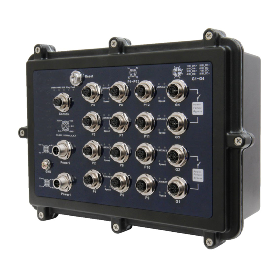
Panel Layouts
Top View
1
1
Reset
3
4
TES-W9124GT-M12X-BP2-24V
PWR1 PWR2
R.M.
Ring
Fault
LNK/ACT
RXD
TXD
N.C.
2
5
Speed
10
1
N.C.
GND
P4
RS-232, 115200bps, 8, N, 1
Console
LNK/ACT
6
Speed
P3
11
V2+
N.C
LNK/ACT
V2-
N.C
Speed
P2
Power 2
7
4
14
GND
LNK/ACT
V1+
N.C
Speed
V1-
N.C
P1
Power 1
1
Bottom View
1
1. Wall-mount screw holes
1907-200-SW9124X541-FX010
Tx+
Rx+
4
5
1 BI_DA+
5 BI_DD+
2 BI_DA-
6 BI_DD-
Reset
3
6
3 BI_DB+
7 BI_DC-
2
7
4 BI_DB-
8 BI_DC+
Rx-
Tx-
1
8
G1~G4
P1~P12
LNK/ACT
LNK/ACT
Speed
Speed
P4
P8
P12
G4
Power
Failure
Bypass
LNK/ACT
LNK/ACT
Speed
Speed
P3
P7
P11
G3
LNK/ACT
LNK/ACT
Speed
Speed
P2
P6
P10
G2
Power
Failure
Bypass
LNK/ACT
LNK/ACT
Speed
Speed
P1
P5
P9
G1
262.00
90.0
12
1. Reset button
2. Power LED
Tx+
Rx+
4
5
1 BI_DA+
5 BI_DD+
3
6
2 BI_DA-
6 BI_DD-
3 BI_DB+
7 BI_DC-
3. R.M. status LED
2
7
4 BI_DB-
8 BI_DC+
Rx-
Tx-
1
8
P1~P12
G1~G4
LNK/ACT
4. Ring status LED
Speed
P8
P12
G4
Power
5. Fault LED
Failure
Bypass
LNK/ACT
6. Console port
Speed
P7
P11
G3
7. Power connector
LNK/ACT
8. Fast Ethernet port
Speed
P6
P10
G2
Power
9. Gigabit Ethernet port with bypass
Failure
Bypass
LNK/ACT
10. Link/ACT LED for Ethernet port
Speed
P5
P9
G1
11. Speed LED for Ethernet port
12. Link/ACT LED for Gigabit Ethernet port
13. Speed LED for Gigabit Ethernet port
14. Ground wire
8
13
9
1
PRINTED ON RECYCLED PAPER
EN50155 Industrial IP-54 managed
Ethernet switch
Installation
Wall-mount
Follow the steps below to install the device to the wall.
Step 1: Screw the Four pieces of wall-mount kits onto bottom side of the switch. A total of four
screws are required.
Step 2: Hold the device upright against the wall.
Step 3: Insert four screws through the holes at the top of the plate and fasten the screws to
the wall.
Instead of screwing the screws in all the
way, it is advised to leave a space of about
2mm to allow room for sliding the switch
between the wall and the screws.
Wiring
For pin assignments of power and console port, please refer to the following tables.
Grounding
Grounding and wire routing help limit the effects of noise due to electromagnetic interference
(EMI). Run the ground connection from the grounding pin on the power connector to the grounding
surface prior to connecting devices.
Power port pinouts
The device supports two sets of power supply and uses the M12 S-coded
4-pin male connector on the front panel for power inputs.
Step 1: Insert a power cable to the power connector on the device.
Step 2: Rotate the outer ring of the cable connector until a snug fit is
achieved. Make sure the connection is tight.
Console port pinouts
The switch has one RS-232 (M12 5pin) console port,
located on the front panel. Use a M12-to-DB9
console cable to connect the console port to your
PC's COM port.
Network Connection
The switch has twelve 10/100Base-T(X) and four 10/100/1000Base-T(X) Ethernet ports in the form
of M12 connector. Depending on the link type, the switch uses CAT 3, 4, 5,5e UTP cables to
connect to network devices (PCs, servers, switches, routers, or hubs). Please refer to the
following table for cable specifications.
Cable
Type
Max. Length
Connector
4-pin female M12
10BASE-T
Cat. 3, 4, 5 100-ohm
UTP 100 m (328 ft)
D-coding connector
4-pin female M12
100BASE-TX
Cat. 5 100-ohm UTP
UTP 100 m (328 ft)
D-coding connector
8-pin female M12
1000BASE-T
Cat. 5/Cat. 5e 100-ohm UTP UTP 100 m (328 ft)
X-coding connector
For pin assignments of the M12 ports, please refer to the following tables.
4-Pin Fast Ethernet Port Definition
1
2
10/100Base-T(X) M12 port with D-Coding
Tx+
Rx+
Pin No.
Description
#1
Tx+
#2
Rx+
Rx-
Tx-
4
3
#3
Tx-
#4
Rx-
Quick Installation Guide
Version 1.0
V+
N.C
V-
N.C
RXD
TXD
N.C.
N.C.
GND
RS-232, 115200bps, 8, N, 1
Advertisement

Subscribe to Our Youtube Channel
Related Manuals for ORiNG TES-W9124GT-M12X-BP2-24V-IP54


Summary of Contents for ORiNG TES-W9124GT-M12X-BP2-24V-IP54
- Page 1 2 BI_DA- 6 BI_DD- Reset 3 BI_DB+ 7 BI_DC- 4 BI_DB- 8 BI_DC+ TES-W9124GT-M12X-BP2-24V G1~G4 P1~P12 TES-W9124GT-M12X-BP2-24V-IP54 can also be managed centralized and PWR1 PWR2 R.M. Ring Fault LNK/ACT LNK/ACT N.C. convenient by Open-Vision, Except the Web-based interface, Telnet and Speed Speed N.C.
- Page 2 For information on operating the device Port configuration, status, statistics, monitoring, security FAX: +886-2-2218-1014 E-mail: support@oringnet.com using ORing’s Open-Vision management utility, please go to ORing website. DHCP Server/Client/Relay SMTP Client Modbus TCP Q I G...
Need help?
Do you have a question about the TES-W9124GT-M12X-BP2-24V-IP54 and is the answer not in the manual?
Questions and answers