Table of Contents
Advertisement
Quick Links
Advertisement
Table of Contents

Related Manuals for Siargo MF5100


Summary of Contents for Siargo MF5100
- Page 1 Gas Mass Flow Meter VB.1.01 Model MF5100 @ 2022 Siargo Ltd. www.Siargo.com...
- Page 2 Santa Clara, CA 95054 Tel: +1(408)969.0368 Email: info@siargo.com © Copyright 2022 by Siargo Ltd. Siargo Ltd. and its subsidiaries reserve the right to change the specifications and/or descriptions without prior notice. For further information and updates, please visit: www.Siargo.com www.Siargo.com MF5100 User Manual...
- Page 3 Do not apply for any unknown or non-specified gases that may damage the product. x For remote data, please be sure the meter is properly configured. www.Siargo.com MF5100 User Manual P a g e...
-
Page 4: Table Of Contents
Technical specifications ..........................23 Technical specifications ........................23 Pressure loss ............................24 Technical notes for the product performance ..................25 Measurement principle ........................25 Precautions for the best performance of the product..............25 www.Siargo.com MF5100 User Manual P a g e... - Page 5 Apply to a different gas medium....................26 Troubleshooting ............................ 27 Warranty and Liability .......................... 28 Service/order contact and other information ..................30 Appendix I: Product evaluation kit ........................31 Appendix II: Document history ........................32 www.Siargo.com MF5100 User Manual P a g e...
-
Page 6: Overview
1. Overview All contact information can be found at the end of this manual. This manual provides essential information for the operation of the MF5100 series of gas mass flow meters for general-purpose gas metrology applications. The product performance, maintenance, and trouble-shooting as well as the information for product order, technical support, and repair are also included. -
Page 7: Receipt / Unpack Of The Products
Flow meter data cable Figure 2.1: MF5100 flow meter and data cable Please check immediately for the integrity of the product as well as the power and data cable, if any abnormal is identified, please notify the distributor/sales representative or manufacturer as soon as you can. -
Page 8: Knowing The Products
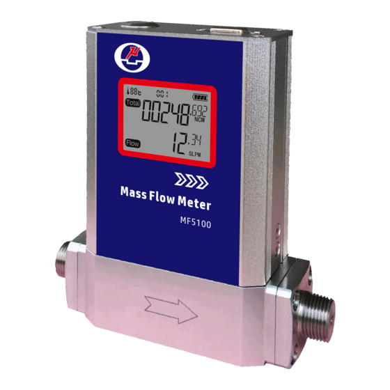
Meter body NPT or other connectors Flow direction Figure 3.1: MF5100 parts description 3.2.LCD description Figure 3.2: LCD symbol illustration. The LCD provides all information that the product measures. Some symbols are reserved for future upgrades, and will not be lighted during the operation. The following table details the meaning of each of the symbols. -
Page 9: Power And Data Cable Description
Modbus address. Status of the battery, when the meter is operating with the battery power. Temperature, for models with temperature option 3.3.Power and data cable description Table 3.2: MF5100 wire assignments. Wire Color Definition Purple 4~20 mA, output... -
Page 10: Mechanical Dimensions
3.4.Mechanical dimensions Figure 3.4: MF5100 meter dimensions Model DN (mm) D (NPTM) L MF5006 3.00 3/8” 132.0 134.0 130.0 32.0 32.0 Φ3.0 MF5008 6.00 3/8” 132.0 134.0 130.0 32.0 32.0 Φ6.0 MF5010 8.00 3/8” 132.0 134.0 130.0 32.0 32.0 Φ8.0 MF5012 12.00... -
Page 11: Battery Installation
(b) Install the battery – for most applications, the battery life should be 3+ years. And re-assemble the back cover of the meter head. www.Siargo.com MF5100 User Manual 10 | P a g e... -
Page 12: Meter Installation
To ensure the measurement accuracy, an upstream straight pipe of length no less than 10DN and a downstream straight pipe of length no less than 5DN should be in place. Please refer to the following recommended installation configuration. www.Siargo.com MF5100 User Manual 11 | P a g e... - Page 13 Please be sure of the power supply range (i.e., 12 ~ 24 VDC) and power supply polarization. If an adapter is other than the one supplied by the manufacturer, make sure the adapter meets industrial standards and has all safety certifications. www.Siargo.com MF5100 User Manual 12 | P a g e...
- Page 14 The strong electromagnetic interference sources close by or any mechanical shocks at the pipeline may also create malfunctioning of the product. e) Slowly open/close valves to prevent abrupt pulse flow impact. www.Siargo.com MF5100 User Manual 13 | P a g e...
-
Page 15: Operation
Half-duplex RS485 Modbus is used for digital data communication. Make sure the wires are properly connected to the receiver side. www.Siargo.com MF5100 User Manual 14 | P a g e... -
Page 16: Starting The Measurement
PLC) can communicate with multiple slaves (the current product) for data exchange and communication parameter configuration. Refer to Table 3.3 for cable connection. 6.5.1 Hardware connection The hardware layer is TIA/EIA-485-A, as illustrated below. In this configuration, the product (MF5100) is a slave. Figure 6.1: RS485 hardware connection www.Siargo.com... -
Page 17: Communication Parameters
Address: The address can be set from 0 to 247 except for 157 (0x9d). 0 is the broadcast address. Function codes: Define the product (MF5100)'s functions/actions (slaves), either execution or response. Data: The address of the register, length of data, and the data themselves. -
Page 18: Function Codes
Write multiple registers 6.5.5 Registers The product (MF5100) has multiple registers available for the assignment of the various functions. With these functions, the user can obtain the data from the products, such as product address and flow rates from the registers, or set the product functions by writing the corresponding parameters. - Page 19 = ((0 + 3452)*1000 + 245)/1000=3452.245. Write Maximum flow rate 0x0085 … 0x0086 Read Description Set the maximum flow rate limit Value type UINT 16 Notes Maximum flow rate limit =(Value(oxoo85)*65536+Vlaue(0x0086))/1000 www.Siargo.com MF5100 User Manual 18 | P a g e...
- Page 20 LCD, replacing the meter address value. If the GC_threshold is set to 10000, this function will be disabled. Write Pulse 0x93 Read Description Set the pulse rate for totalized flow rate www.Siargo.com MF5100 User Manual 19 | P a g e...
-
Page 21: Analog Output
The loop resistor connection is illustrated below. The current output load depends on the power supply (the yellow area in the graph). The maximum load resistor, R , with a 24Vdc supply, will be 850Ohm. Figure 6.2: 4 ~ 20 mA analog output. www.Siargo.com MF5100 User Manual 20 | P a g e... -
Page 22: Pulse Output
Figure 6.3: Pulse output for accumulated flow rate. 6.6.3 Voltage output For 0~5.0Vdc analog output, an external power supply is required. The connection of the analog output is illustrated below. Figure 6.4: Voltage output connection. www.Siargo.com MF5100 User Manual 21 | P a g e... -
Page 23: Product Selection
Model DN (”) (mm) sccm SLPM SCFM MF5106 3/8” 30~30000 0.30~30.00 MF5108 3/8” 0.50~50.00 0.02~2.00 MF5110 10.0 3/8” 1.20~120.00 0.04~4.20 MF5112 12.0 1/2” 3.00~300.00 0.10~10.00 MF5119 19.0 3/4” 8.00~800.00 0.28~28.00 www.Siargo.com MF5100 User Manual 22 | P a g e... -
Page 24: Technical Specifications
2. All specifications listed in the following table unless otherwise noted apply for calibration conditions at 20°C and 101.325 kPa absolute pressure with air. The product is horizontally mounted at the time of calibration. www.Siargo.com MF5100 User Manual 23 | P a g e... -
Page 25: Pressure Loss
8.2 Pressure loss www.Siargo.com MF5100 User Manual 24 | P a g e... -
Page 26: Technical Notes For The Product Performance
Another key point to comparing the different flow meters is that as long as the fluidic flow is a continuous flow without pulsation, then the fluidic dynamic will have the system following the Bernoulli equation: www.Siargo.com MF5100 User Manual 25 | P a g e... -
Page 27: Particle Contamination And Fluidic Cleanness
For further information, please contact the manufacturer. www.Siargo.com MF5100 User Manual 26 | P a g e... -
Page 28: Troubleshooting
Offset unstable Circuitry instability Check system, power off No digital interface Wrong address, software Check commands, connection No wireless, BT cannot pair Wrong model, data jam Check model, power off/on www.Siargo.com MF5100 User Manual 27 | P a g e... -
Page 29: Warranty And Liability
The products returned under warranty to Siargo shall be at the user or purchaser's risk of loss and will be returned, if at all, at Siargo's risk of loss. Purchasers or users are deemed to have accepted this limitation of warranty and liability, which contains the complete and exclusive limited warranty of Siargo. - Page 30 (5) Any damages incurred by the incorrect usage of the products; (6) Siargo does not provide any warranty on finished goods manufactured by others. Only the original manufacturer's warranty applies;...
-
Page 31: Service/Order Contact And Other Information
12.Service/order contact and other information Siargo Ltd. is making every effort to ensure the quality of the products. In case of questions and or product support, please contact your direct sales, or in case you need additional assistance, please contact customer service at the address listed below. We will respond to your request in a timely fashion and work with you toward your complete satisfaction. -
Page 32: Appendix I: Product Evaluation Kit
Appendix I: Product evaluation kit Siargo offers a product evaluation kit, including a digital data converter, USB data cable, and User Application software, that allows the user to evaluate the product performance on a Microsoft Windows-based computer. For some simple applications with digital data transfer, this kit could serve the purpose. -
Page 33: Appendix Ii: Document History
¾ Corrected the calibrated condition (Specifications). Revision A.5 (July 2018): ¾ Added the installation instructions (Installation Instructions). Revision A.4 (October 2017): ¾ Added maximum overflow and maximum flow change (Specifications); ¾ Added the revision history. www.Siargo.com MF5100 User Manual 32 | P a g e...
Need help?
Do you have a question about the MF5100 and is the answer not in the manual?
Questions and answers