Table of Contents
Advertisement
Quick Links
Advertisement
Table of Contents

Related Manuals for Siargo MF5900 Series


Summary of Contents for Siargo MF5900 Series
- Page 1 Gas Mass Flow Meter VA.1 Model MF5900 ...
- Page 2 User Manual Document No. 12‐2021‐MF59 EN Issue date: 2021.12 Revision: VA.1 Siargo Ltd. 3100 De La Cruz Boulevard, Suite 210 Santa Clara, CA 95054 USA Tel: +1(408)969.0368 Email: info@siargo.com © Copyright 2021 by Siargo Ltd. Siargo Ltd. and its subsidiaries reserve the right to change the specifications and/or descriptions without prior notice. For further information and updates, please visit: www.Siargo.com www.Siargo.com MF5900 User Manual 1 | P a g e ...
- Page 3 Only the trained or qualified personnel shall be allowed to perform product services. Use with caution! Be cautious for the electrical safety, even it operates at a low voltage, any electrical shock might lead to some unexpected damages. The gas to be measured should be clean and free of particles. Do not apply this meter for liquid medium. Do not apply for any unknown or non‐specified gases that may damage the product. For wireless data with NB‐IoT, please be sure the network is available. www.Siargo.com MF5900 User Manual 2 | P a g e ...
-
Page 4: Table Of Contents
5.4.5 Reset or calibrate the offset .................. 15 5.4.6 Gas conversion factor (GCF) for different gas measurement .......... 15 5.4.7 Select the display language ................... 16 5.4.8 Select the totalizer or accumulated flow rate unit ............ 16 5.4.9 Select the instant flow rate unit .................. 16 5.4.10 Set an alarm: upper instant flow rate limit .............. 17 5.4.11 Set an alarm: lower instant flow rate limit .............. 17 5.4.12 Set an alarm: totalizer or accumulated flow rate limit ............. 1 8 5.4.13 Change the default password .................. 1 8 5.4.14 Reset the totalizer or accumulated flow rate .............. 19 5.4.15 Exit the MENU ...................... 19 www.Siargo.com MF5900 User Manual 3 | P a g e ... - Page 5 8.2.1 Comparison with a third party reference meter ............... 29 8.2.2 Particle contamination and fluidic cleanness .............. 30 8.2.3 Apply to a different gas medium .................. 30 9. Troubleshooting .................. 3 1 10. Warranty and Liability ................ 3 2 11. Service contact .................. 3 4 Appendix I: Product evaluation kit .............. 3 5 Appendix II: Document history ............... 3 6 www.Siargo.com MF5900 User Manual 4 | P a g e ...
-
Page 6: Overview
The technology also opts for additional flow and medium parameter detection. Please stay tuned for our next upgrade. Siargo is committed to continuing product innovation while offering the best value to our customers. This serial of products is designed for general purpose mass flow sensing and control purposes. The wetted materials of the products are compatible with most of the common gases such as oxygen, nitrogen, air, argon, carbon dioxide, etc. Siargo also offers a wide spectrum of off‐the‐shelf and customized flow, pressure, temperature/humidity, and gas concentration sensing products and provides integration and turn‐key solutions to our customers. Please contact the manufacturer for further information. ... -
Page 7: Receipt / Unpack Of The Products
If the packing box is intact, proceed to open the packing box, and you shall find the product (either the meter or the meter with valve per the actual order). The power adapter and/or data cable as shown below may also be found according to your actual order. Flow meter data cable Figure 2.1: MF5900 flow meter and accessories Please check immediately for the integrity of the product as well as the power and data cable, if any abnormal is identified, please notify the distributor/sales representative or manufacturer as soon as you can. If any defects are confirmed, an exchange shall be arranged immediately via the original sales channel. (Note: the LCD screen shall not be lighted until the power cable is plugged in). This user manual shall also either be included in the packing box or via an online request for an electronic version. In most cases, this manual shall be made available to the customer before the actual order. www.Siargo.com MF5900 User Manual 6 | P a g e ... -
Page 8: Knowing The Products
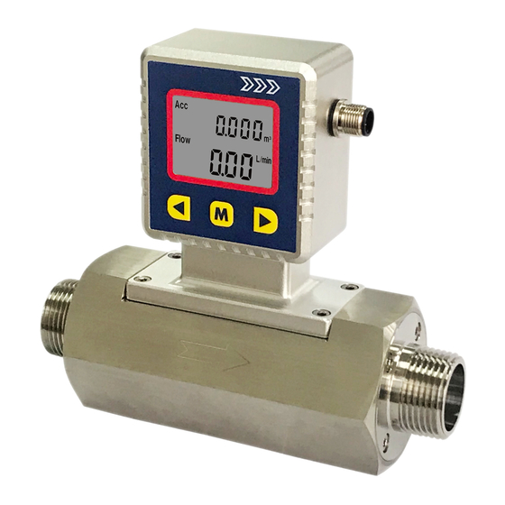
Some symbols are reserved for future upgrades, and will not be lighted during the operation. The following table details the meaning of each of the symbols. Figure 3.2: LCD symbol illustration. Table 3.1: Symbols description The top row. The default displays the totalizer or accumulated flow rate in ACC L (liters), m (cubic meters), or SCF (standard cubic feet). It also displays pressure (if kPa lights up) or temperature (if °C lights up)*. The 2 row. Displays instant flow rate in L/min (Liters per minute) or Flow SCFH (standard cubic feet per hour) or m /h (cubic meters per hour). *Note: Both the pressure and temperature sensors can be integrated with the current product but not with the default models. Please contact the manufacturer for further information. www.Siargo.com MF5900 User Manual 7 | P a g e ... -
Page 9: Power And Data Cable Description
W1 H D MF5912 170 130 61 58 147 NPT 1/2” MF5925 170 130 67 58 153 NPT 1” MF5940 173 130 75 68 163 NPT 1‐1/2” MF5950 200 150 76 68 165 NPT 2” www.Siargo.com MF5900 User Manual 8 | P a g e ... -
Page 10: Installation
Figure 4.1: MF5900 meter installation a) Upon opening the package, the product's physical integrity should be inspected to ensure no visual damage. b) Before installation of the product, please ensure that the pipe debris or particles or any other foreign materials are completed removed. c) Cautions during installation: i) It is preferable to first install/connect the meter inlet and then the outlet end of the meter; To ensure the measurement accuracy, an upstream straight pipe of length no less than 10DN and a downstream straight pipe of length no less than 5DN should be in place. Please refer to the following recommended installation configuration. www.Siargo.com MF5900 User Manual 9 | P a g e ... - Page 11 (ii) If the upstream or downstream pipe size is different from that of the product, the size of the installation line pipe diameter(s) should be larger than the flow channel (pipe) size of the meters to be installed. For some typical situations, please follow the installation recommendation detailed in the following sketches. (c) 2x90‐degree elbow, 3 D (d) Pipe size‐reduction (e) Pipe size expansion (f) Control valve at upstream or downstream Figure 4.3: MF5900 meter installation (iii) During installation, please make sure no foreign materials (such as water, oil, dirt, particles, etc.) entering into the installation pipeline. www.Siargo.com MF5900 User Manual 10 | P a g e ...
- Page 12 Note: because the meter has a large dynamical measurement range, it could be normal if you see the small instant flow rate before you open the valve as there could be some leakage. However, make sure the meter reads null when there is no flow present in the pipeline. h) This will conclude the installation. Cautions a) Don't alter any parts of the product. b) Ensure the electrical connection is properly done per the instructions. c) Make sure no mechanical stresses in the connections. d) The strong electromagnetic interference sources close by or any mechanical shocks at the pipeline may also create malfunctioning of the product. e) Slowly open/close valves to prevent abrupt pulse flow impact. www.Siargo.com MF5900 User Manual 11 | P a g e ...
-
Page 13: Operation And Menu Description
Before connecting the meter with external DC power or an AC‐DC adapter, make sure the supply voltage is within the range of the specified ones in Section 7. Be cautious that the standard electrical device precautions such as EDS (electrostatic discharge) and DC voltage are observed. Excessive electrostatic discharge may damage the product. The power and data port is a standard M12. The manufacturer‐supplied M12 cable has the screw locking fixture. Lock the cable and make sure it is properly engaging and will not be accidentally got unplugged. Half‐duplex RS485 Modbus is used for digital data communication. Make sure the wires are properly connected and configured at the receiver side. www.Siargo.com MF5900 User Manual 12 | P a g e ... -
Page 14: Meter Menu Description
5.4.2 MENU entry with a verified password At the flow measurement (main) display, press the central “M” MENU key, it will enter into the password setting and verification MENU. The default password is “11111”. If the password is incorrect, the display will return to the main display. To enter a new password, press the “Up” or “Down” key to change the digit that flashes, and press the “M” key to confirm. Repeat this process for all 5 digits and the meter will enter into the menu setting interfaces/screen. www.Siargo.com MF5900 User Manual 13 | P a g e ... -
Page 15: Set The Rs485 Modbus Address
Display screen. 5.4.4 Set the RS485 communication baud rate Following the above‐mentioned steps, at the MENU setting screen, use the “Up” or “Down” key to select F3 – bPS and then press the “M” key to set the RS485 communication baud rate. There are 6 baud rates selectable, depending on your system requirements: 4800, 9600, 19200, 38400, 57600, and 115200. The default baud rate is 9600. Use the “Up” or “Down” key to select the desired one and press the “M” key to confirm. The display will then return to the F3 – bPS screen, which indicates the task is completed. Use the “Up” or “Down” key to select F99 – qUIT and the “M” key to exit the MENU and return to the Main Display screen. www.Siargo.com MF5900 User Manual 14 | P a g e ... -
Page 16: Reset Or Calibrate The Offset
The GCF for air is 1000. Note: If the meter during purchase is ordered for a special real gas calibration, contact the manufacturer before further proceeding. Following the above‐mentioned steps, at the MENU setting screen, use the “Up” or “Down” key to select F12 – GCF. Press the “M” key to confirm, and it will open the sub‐MENU showing the current gas conversion value. Use the “Up” or “Down” and the “M” confirming key to input the desired value, and press the “M” key again to complete the task. The display will then return to the F12 – GCF screen, which indicates the task is completed. Use the “Up” or “Down” key to select F99 – qUIT and the “M” key to exit the MENU and return to the Main Display screen. This GCF factor can also be used equivalent to the “K” factor to adjust the meter due to the system deviations. Take 3 to 5 data points using your preferred reference meter, and perform the least square fitting to identify the K factor, and input here to make the meter synchronize with your system. www.Siargo.com MF5900 User Manual 15 | P a g e ... -
Page 17: Select The Display Language
The display will then return to the F31 – UnT‐A screen, which indicates the task is completed. Use the “Up” or “Down” key to select F99 – qUIT and the “M” key to exit the MENU and return to the Main Display screen. 5.4.9 Select the instant flow rate unit This function allows the user to select the instant flow rate units of a standard liter per minute (SLPM) or standard cubic feet per hour (SCFH). Following the above‐mentioned steps, at the MENU setting screen, use the “Up” or “Down” key to select F32 – UnT‐F. Press the “M” key to confirm, and it will open the sub‐ MENU showing the current unit. Use the “Up” or “Down” and the “M” confirming key to select the desired one, and press the “M” key again to complete the task. The display will then return www.Siargo.com MF5900 User Manual 16 | P a g e ... -
Page 18: Set An Alarm: Upper Instant Flow Rate Limit
The alarm will be off once the metering value is above the set value. The flow rate has two decimal points with a minimum of 0.00. Following the above‐mentioned steps, at the MENU setting screen, use the “Up” or “Down” key to select F52 – ALm‐L. Press the “M” key to confirm, and it will open the sub‐MENU showing a default flow rate of 000.00 (full scale 250 SLPM) or 0000.0 (full scale 1200, 2500 and 4500 SLPM) . Use the “Up” or “Down” and the “M” confirming key to enter the desired one, and press the “M” key again to complete the task. The display will then return to the F52 – ALm‐L screen, which indicates the task is completed. Use the “Up” or “Down” key to select F99 – qUIT and the “M” key to exit the MENU and return to the Main Display screen. www.Siargo.com MF5900 User Manual 17 | P a g e ... -
Page 19: Set An Alarm: Totalizer Or Accumulated Flow Rate Limit
“Down” and the “M” confirming key to enter the desired one, and press the “M” key again to complete the task. The display will then return to the F53 – ALm‐A screen, which indicates the task is completed. Use the “Up” or “Down” key to select F99 – qUIT and the “M” key to exit the MENU and return to the Main Display screen. 5.4.13 Change the default password For data safety, it is recommended that the default password of 11111 should be changed when the first use of this product. Following the above‐mentioned steps, at the MENU setting screen, use the “Up” or “Down” key to select F91 – PASS. Press the “M” key to confirm, and it will open the sub‐MENU showing the default password of 11111. Use the “Up” or “Down” and the “M” confirming key to enter the desired one, and press the “M” key again to complete the task. The display will then return to the F91 – PASS screen, which indicates the task is completed. Use the “Up” or “Down” key to select F99 – qUIT and the “M” key to exit the MENU and return to the Main Display screen. Please keep the changed password in a safe yet accessible place. In case it is unrecoverable, please contact the manufacturer to obtain a special password to access the meter MENU. www.Siargo.com MF5900 User Manual 18 | P a g e ... -
Page 20: Reset The Totalizer Or Accumulated Flow Rate
9999999, the register will stop accumulating once the value is reached. At this time, it is necessary to reset this register. Following the above‐mentioned steps, at the MENU setting screen, use the “Up” or “Down” key to select F92 – CLr‐ A. Press the “M” key to confirm, and it will open the sub‐MENU for resetting the value. Use the “Up” or “Down” to select and the “M” confirming key to execute, and press the “M” key again to complete the task. The display will then return to the F92 – CLr‐A screen, which indicates the task is completed. Use the “Up” or “Down” key to select F99 – qUIT and the “M” key to exit the MENU and return to the Main Display screen. 5.4.15 Exit the MENU At the MENU settings, use the “Up” or “Down” key to select the F99 – qUIT option and press the “M” confirming key to exit the MENU settings and return to the Main Display screen. www.Siargo.com MF5900 User Manual 19 | P a g e ... -
Page 21: Menu Key Sequence For The Settings
5.4.16 MENU key sequence for the settings Figure 5.2: Menu operation www.Siargo.com MF5900 User Manual 20 | P a g e ... -
Page 22: Rs485 Modbus Communication Protocol
PLC) can communicate with multiple slaves (the current product) for data exchange and communication parameter configuration. Refer to Table 3.2 for cable connection. 5.5.1. Hardware connection The hardware layer is TIA/EIA‐485‐A, as illustrated below. In this configuration, the product (MF5900) is a slave. Figure 5.3: RS485 hardware connection 5.5.2. Communication parameters The PC UART communication parameters are listed in the table 5.1. Table 5.1: Communication parameters Protocol Parameters RTU Baud rate (Bits per second) 9600 bps Start bits 1 Data bits 8 Stop bits 1 Even/Odd parity None Bits period 104.2 µsec Bytes period 1.1458 msec Maximum data length 20 Maximum nodes 247 www.Siargo.com MF5900 User Manual 21 | P a g e ... -
Page 23: Frame
The Modbus function codes applied for the product are the sub‐class of the standard Modbus function‐codes. These codes are used to set or read the registers of the product: Code Name Functions 0x03 Read register Read register(s) 0x06 Set single register Write one single 16‐bit register 0x10 Set multiple registers Write multiple registers 5.5.5. Registers The product (MF5900) has multiple registers available for the assignment of the various functions. With these functions, the user can obtain the data from the products, such as product address and flow rates from the registers, or set the product functions by writing the corresponding parameters. The currently available registers are listed in the following table, and the registers may be customized upon contact the manufacturer. Where R: read; W: write‐only; W/R: read and write. www.Siargo.com MF5900 User Manual 22 | P a g e ... - Page 24 Notes 0 is the broadcast address. Write N Serial number, SN 0x0030 Read Y Description Series Number of the product, SN Value type UINT8 (12 bits) SN= value(0x0030), value(0x0031),….,value (0x0035); Receiving 12 bits as: Notes 2A 47 37 41 45 49 30 32 30 35 38 2A , the corresponding Serial is *G7AEI02058*. Number Write N Flow rate 0x003A ~ 0x003B Read Y Description Current flow rate Value type UINT 16 Notes Flow rate = [Value (0x003A)*65536 + value (ox003B)]/1000 www.Siargo.com MF5900 User Manual 23 | P a g e ...
- Page 25 Y GCF 0x008B Read Y Description The gas conversion factor for using with gas different from calibration gas Value type UINT 16 The air (default) is 1000, normally read from register 0x008B. The product will disable this function with write protection once the Notes metering gas is confirmed with the proper GCF. For a specific GCF value, please contact the manufacturer. Write Y Units 0x0090 Read Y Description Units of instant flow rate and totalizer or accumulated flow rate Value type UINT 16 1 ‐ instant flow rate unit: SLPM, totalizer, or accumulated flow rate unit: Nm . 3 ‐ instant flow rate unit: SCFH, totalizer, or accumulated flow rate unit: SCF. Notes The default value is 1. For example, when the user reads “1” from register 0x0090, the instant flow rate unit is SLPM, the totalizer or accumulated flow rate unit is Nm . www.Siargo.com MF5900 User Manual 24 | P a g e ...
- Page 26 When the flow rate is below a set value, an alarm will be triggered. Notes e.g.: for a totalizer alarm of 100 SLPM, the user will read “1 (0x0001)” from register 0x009A and “58208 (0Xd4c0)” from register 0x009B, therefore Current flow rate = (1*65536+54464)/1000 = 120.000 Write Y Password 0x00AE ~ 0x00AF Read Y Description Change the default password Value type UINT 32 Password values ALM‐L = Value (0x00AE)*65536 + Value (0x00AF) Notes Available: 00000 ~ 99999 Write Y Offset calibration 0x00F0 Read N Description Reset or calibrate the offset Value type UINT 16, Fixed value 0xAA55 To reset or calibrate the offset, write 0xAA55 to register 0x0027. Notes When you execute this function, make sure there is NO flow in the flow channel. www.Siargo.com MF5900 User Manual 25 | P a g e ...
-
Page 27: 20 Ma Analog Interface
Notes be enabled (write protection is disabled). After the write execution is completed, the firmware will automatically re‐enable the write protection. Only Address and Baud rate will not be write‐protected. 5.6 4~20 mA Analog interface The loop resistor connection is illustrated below. The current output load depends on the power supply (the yellow area in the graph). The maximum load resistor, R , with a 24Vdc supply, will be 850Ohm. Figure 5.4: Analog output. www.Siargo.com MF5900 User Manual 26 | P a g e ... -
Page 28: Product Selection And Order Information
5000 150 MF5950 50 NPT 2” 4500 9500 270 6.2 Order contact and customer support The sales offices and the sales distributors/representatives are listed at the end of this document. For small quantities, the order can be placed either through the Siargo website: www.siargo.com or the sales office. For large quantities, please contact the sales office, distributors, or sales representatives. Siargo is making every effort to ensure the quality of the products. In case of questions and/or product supports, please contact the customer service listed at the end of the document. www.Siargo.com MF5900 User Manual 27 | P a g e ... -
Page 29: Technical Specifications
‐20 ~ 70 °C Reference conditions 20°C, 101.325 kPa, air Protection IP66 (NEMA 4x) Fluid compatibility Non‐corrosive CE EN61326‐1; ‐2; ‐3 MF5912 MF5925 MF5940 MF5950 Maximum overflow 400 2000 4500 8000 SLPM Maximum flow change 60 300 750 1200 SLPM/sec Note: For other features or specifications not listed, please contact the manufacturer. www.Siargo.com MF5900 User Manual 28 | P a g e ... -
Page 30: Technical Notes For The Product Performance
Another key point to compare the different flow meter is that as long as the fluidic flow is a continuous flow without pulsation, then the fluidic dynamic will have the system following the Bernoulli equation: www.Siargo.com MF5900 User Manual 29 | P a g e ... -
Page 31: Particle Contamination And Fluidic Cleanness
Therefore, measurement by the meter for a gas medium other than the calibration gas would bear larger measurement errors, particularly at the low Reynold number range where the laminar flow has a sensitive flow profile. www.Siargo.com MF5900 User Manual 30 | P a g e ... -
Page 32: Troubleshooting
Possible causes Actions Power not connected; battery Connect the power, check the empty cable Cable connection incorrect Check cable No signal / display No flow or clogging Check flow and contamination Power regulator failure Return to factory Sensor failure Return to factory Large errors or unexpected Particles, fluid type Check system flow rate Erroneous or large noise Vibration, unstable flow Check system Offset unstable Circuitry instability Check system, power off No digital interface Wrong address, software Check commands, connection No wireless, BT cannot pair Wrong model, data jam Check model, power off/on www.Siargo.com MF5900 User Manual 31 | P a g e ... -
Page 33: Warranty And Liability
Siargo makes no warranty, representation, or guarantee and shall not assume any liability regarding the suitability of the products described in this manual for any purposes that are not specified in this manual. The users shall be held for full responsibility for validating the performance and suitability of the products for their particular design and applications. For any of the misusage of the products out of the scope described herein, the user shall indemnify and hold Siargo and its officers, employees, subsidiaries, affiliates, and sales channels harmless against all claims, costs, damages, and expense or reasonable attorney fee from direct or indirect sources. Siargo makes no other warranty, express or implied, and assumes no liability for any special or incidental damage or charges, including but not limited to any damages or charges due to installation, ... - Page 34 (2) Products that have been subject to chemical attacks, including exposure to corrosive substances or contaminants. In the case of battery usage, long term discharge or leakage induced damages; (3) Products that have been opened or dismantled for whatever reasons; (4) Products that have been subject to working conditions beyond the technical specification as described by this manual or related datasheet published by the manufacturer; (5) Any damages incurred by the incorrect usage of the products; (6) Siargo does not provide any warranty on finished goods manufactured by others. Only the original manufacturer's warranty applies; (7) Products that are re‐sold by unauthorized dealers or any third parties. www.Siargo.com MF5900 User Manual 33 | P a g e ...
-
Page 35: Service Contact
11. Service contact Siargo Ltd. is making every effort to ensure the quality of the products. In case of questions, and or product supports, please contact customer service at the address listed below. We will respond to your request in a timely fashion and will work with you toward your complete satisfaction. Customer service and all orders should be addressed to Siargo Ltd. 3100 De La Cruz Boulevard, Suite 210, Santa Clara, California 95054, USA Phone: +01(408)969‐0368 Email: info@Siargo.com For orders, please provide an accurate and full postal address. Siargo will not ship to P.O. Boxes or via a third party. For further information and updates, please visit www.Siargo.com. www.Siargo.com MF5900 User Manual 34 | P a g e ... -
Page 36: Appendix I: Product Evaluation Kit
Each converter has a fixed cable that can be directly connected to the product. The USB Cable to connect cable connected to the PC is also included. to the product For most of the product, the power from the PC via the USB cable will be sufficient to power the sensor product, no external power will be USB cable to required. However, for multiple sensors in serial, connect to PC the power via the USB cable may not be enough, an external power adapter with 8~24Vdc will be External power required. adapter (optional) www.Siargo.com MF5900 User Manual 35 | P a g e ... -
Page 37: Appendix Ii: Document History
Appendix II: Document history 12.2021 VA.1 ‐ Corrections. 03.2021 VA.0 ‐ First release. www.Siargo.com MF5900 User Manual 36 | P a g e ...
Need help?
Do you have a question about the MF5900 Series and is the answer not in the manual?
Questions and answers