
Related Manuals for Siargo MF5000


Summary of Contents for Siargo MF5000
- Page 1 Gas Mass Flow Meter VE.2 Model MF5000 Sold in North America by: Servoflo Corporation 75 Allen Street Lexington, MA 02472 www.servoflo.com/info@servoflo.com 781-862-9572...
- Page 2 User Manual Document No. 04‐2022‐M7 EN Issue date: 2022.04 Revision: VE.2 Siargo Ltd. 3100 De La Cruz Boulevard, Suite 210 Santa Clara, CA 95054 USA Tel: +1(408)969.0368 Email: info@siargo.com © Copyright 2022 by Siargo Ltd. Siargo Ltd. and its subsidiaries reserve the right to change the specifications and/or descriptions without prior notice. For further information and updates, please visit: www.Siargo.com www.Siargo.com MF5000 User Manual 1 | P a g e ...
- Page 3 Only the trained or qualified personnel shall be allowed to perform product services. Use with caution! Be cautious for the electrical safety, even it operates at a low voltage, any electrical shock might lead to some unexpected damages. The gas to be measured should be clean and free of particles. Do not apply this meter for liquid medium. Do not apply for any unknown or non‐specified gases that may damage the product. For remote data, please be sure the meter is properly configured. www.Siargo.com MF5000 User Manual 2 | P a g e ...
-
Page 4: Table Of Contents
5.4.6 Gas conversion factor (GCF) for different gas measurement .......... 17 5.4.7 Set the 2nd‐correction factor .................. 1 8 5.4.8 Set the Response time .................... 1 8 5.4.9 Set the unit for the accumulated or totalized flow rate ............ 19 5.4.10 Set the unit for the instant flow rate ................ 19 5.4.11 Change the default password .................. 20 5.4.12 Reset the accumulated or totalized flow rate .............. 20 5.4.13 Reset the 2nd‐correction factor .................. 21 5.4.14 Exit the MENU ...................... 21 5.4.15 MENU key sequence for the settings ................ 22 www.Siargo.com MF5000 User Manual 3 | P a g e ... - Page 5 Precautions for the best performance of the product .......... 35 8.2.1 Comparison with a third party reference meter ............... 35 8.2.2 Particle contamination and fluidic cleanness .............. 36 8.2.3 Apply to a different gas medium .................. 36 9. Troubleshooting .................. 3 7 10. Warranty and Liability ................ 3 8 11. Service contact .................. 4 0 Appendix I: Product evaluation kit .............. 4 1 Appendix II: Document history ............... 4 2 www.Siargo.com MF5000 User Manual 4 | P a g e ...
-
Page 6: Overview
generation of the MF5000 series of gas mass flow meters for general‐purpose gas metrology. The product performance, maintenance, and trouble‐shooting as well as the information for product order, technical support, and repair are also included. MF5000 mass flow meters are designed for general purpose precise industrial gas measurement, monitor, or control. The meter series cover a wide dynamic flow range with a working pressure rating of up to 1.5MPa, and a temperature ranging from ‐20 to 60°C. The meters are operated with Siargo’s proprietary MEMS calorimetric mass flow sensors together with the smart control electronics. The sensor surface is passivated with silicon nitride ceramic ... -
Page 7: Receipt / Unpack Of The Products
2. Receipt / unpack of the products Upon receipt of the products, please check the packing box before the dismantlement of the packing materials. Ensure no damages during shipping. If any abnormality is observed, please contact and notify the carrier who shipped the product and inform the distributors or sales representatives if the order is not placed directly with the manufacturer, otherwise, the manufacturer should be informed as well. For any further actions, please refer to the return and repair section in this manual. If the packing box is intact, proceed to open the packing box, and you shall find the product (either the meter or the meter with the valve per the actual order). The power adapter and/or data cable as shown below may also be found according to your actual order. Flow meter data cable Figure 2.1: MF5000 flow meter and data cable Please check immediately for the integrity of the product as well as the power and data cable, if any abnormal is identified, please notify the distributor/sales representative or manufacturer as soon as you can. If any defects are confirmed, an exchange shall be arranged immediately via the original sales channel. (Note: the LCD screen shall not be lighted until the power cable is plugged in). This user manual shall also either be included in the packing box or via an online request for an electronic version. In most cases, this manual shall be made available to the customer before the actual order. The cable is a standard one with an M12 connector. www.Siargo.com MF5000 User Manual 6 | P a g e ... -
Page 8: Knowing The Products
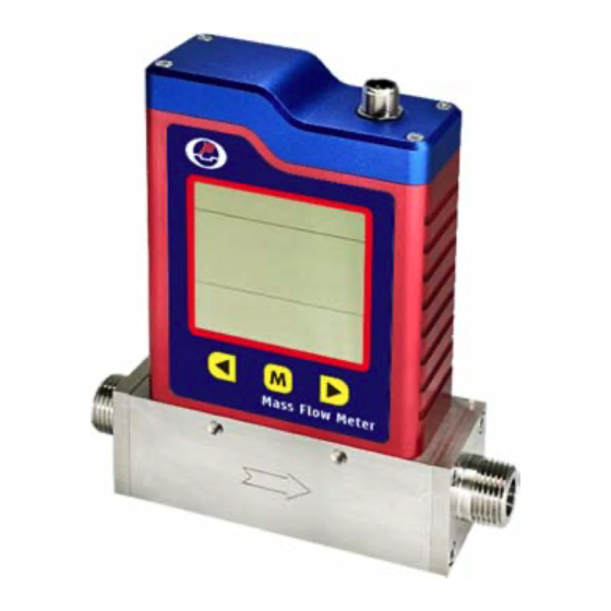
NPT or other connectors Flow direction Figure 3.1: MF5000 parts description 3.2. CD description Figure 3.2: LCD symbol illustration. The LCD provides all information that the product measures. Some symbols are reserved for future upgrades, and will not be lighted during the operation. The following table details the meaning of each of the symbols. www.Siargo.com MF5000 User Manual 7 | P a g e ... -
Page 9: Power And Data Cable Description
Please contact the manufacturer for further information. 3.3. Power and data cable description Table 3.2: MF5o00 wire (M12) assignments. Wire Color Definition 1 Brown 12 ~ 24 Vdc 2 White RS485 B 3 Blue GND, common ground Socket Cable 4 Black RS485 A 5 Gray 4 ~ 20mA output Figure 3.3: MF5000 socket and cable www.Siargo.com MF5000 User Manual 8 | P a g e ... -
Page 10: Mechanical Dimensions
Figure 3.4: MF5000 meter dimensions Model DN (mm) D (NPTM) L MF5003 3 1/8” 138 MF5006 6 1/4” 144 MF5008 8 3/8” 144 MF5012 12 1/2” 150 MF5019 19 3/4” 182.5 www.Siargo.com MF5000 User Manual 9 | P a g e ... -
Page 11: Installation
Figure 4.1: MF5000 meter installation Please follow the following steps to complete the installation: a) Upon opening the package, the product's physical integrity should be inspected to ensure no visual damage. b) Before installation of the product, please ensure that the pipe debris or particles or any other foreign materials are completed removed. c) Cautions during installation: i) It is preferable to first install/connect the meter inlet and then the outlet end of the meter; To ensure the measurement accuracy, an upstream straight pipe of length no less than 10DN and a downstream straight pipe of length no less than 5DN should be in place. Please refer to the following recommended installation configuration. www.Siargo.com MF5000 User Manual 10 | P a g e ... - Page 12 (a) 90‐degree elbow or T‐piece (b) 2x90‐degree elbow Figure 4.2: MF5000 meter installation (ii) If the upstream or downstream pipe size is different from that of the product, the size of the installation line pipe diameter(s) should be larger than the flow channel (pipe) size of the meters to be installed. For some typical situations, please follow the installation recommendation detailed in the following sketches. (c) 2x90‐degree elbow, 3 D (d) Pipe size‐reduction (e) Pipe size expansion (f) Control valve at upstream or downstream Figure 4.3: MF5000 meter installation (iii) During installation, please make sure no foreign materials (such as water, oil, dirt, particles, etc.) enter the installation pipeline. www.Siargo.com MF5000 User Manual 11 | P a g e ...
- Page 13 Note: because the meter has a large dynamical measurement range, it could be normal if you see the small instant flow rate before you open the valve as there could be some leakage. However, make sure the meter reads null when there is no flow present in the pipeline. h) This will conclude the installation. Cautions a) Don't alter any parts of the product. b) Ensure the electrical connection is properly done per the instructions. c) Make sure no mechanical stresses in the connections. d) The strong electromagnetic interference sources close by or any mechanical shocks at the pipeline may also create malfunctioning of the product. e) Slowly open/close valves to prevent abrupt pulse flow impact. www.Siargo.com MF5000 User Manual 12 | P a g e ...
-
Page 14: Operation And Menu Description
Although this product complies with the CE‐required EMC regulations, it also requires the product to be used according to the standard electrical device practice. Before connecting the meter with external DC power or an AC‐DC adapter, make sure the supply voltage is within the range of the specified ones in Section 7. Be cautious that the standard electrical device precautions such as EDS (electrostatic discharge) and DC voltage are observed. Excessive electrostatic discharge may damage the product. The manufacturer‐supplied power and data cable have a locking fixture. Lock the cable and make sure it is properly engaging and will not be accidentally got unplugged. Half‐duplex RS485 Modbus is used for digital data communication. Make sure the wires are properly connected to the receiver side. www.Siargo.com MF5000 User Manual 13 | P a g e ... -
Page 15: Meter Menu Descriptions
5.4 Meter MENU descriptions Left MENU Right Figure 5.1: MF5000 keyboard The meter has a front 3‐key keyboard for the user to set the desired functions, access data, and check the status. The Menu key (M) is at the central position that allows the user to select a function and confirmation or other related actions that will be detailed below. Two keys (“Left” and “Right”) to select the menu and sub‐menu. 5.4.1 Starting the measurement Once the power is supplied and no abnormal issues are observed, the meter is ready to perform the measurements. The default display is for the mass flow measurement having two numerical lines on the LCD. The middle line is the accumulated or totalized flow rate, and the lower line is the instant flow rate. The upper line will light up when the pressure or temperature option is selected. The display characters are limited by the LCD capability, the following table is the illustration. www.Siargo.com MF5000 User Manual 14 | P a g e ... -
Page 16: Menu Entry With A Verified Password
The Modbus address has 3 digits, which can be any number between 001 to 255. Press the “M” key to enter into the change address screen. Press the “Up” or “Down” key to change the flashing digits, and then press the “M” key to confirm. After the address is set, the display will return to F2 ‐ Addr, which indicates the task is completed. Press the “Up” or “Down” key to select F99 ‐ qUIT and the “M” key to exit the MENU and return to the Main Display screen. www.Siargo.com MF5000 User Manual 15 | P a g e ... -
Page 17: Set The Rs485 Communication Baud Rate
MENU setting screen, use the “Up” or “Down” key to select F11 ‐ oFFST. Before performing the task, make sure there is absolutely no flow in the flow channel, otherwise, it will create even bigger erroneous measurement results. Press the “M” key to confirm the task, and it will open the sub‐ MENU asking you to confirm. Use the “Up” or “Down” key to select the desired one and press the “M” key to confirm. The display will then return to the F11 ‐ oFFST screen, which indicates the task is www.Siargo.com MF5000 User Manual 16 | P a g e ... -
Page 18: Gas Conversion Factor (Gcf) For Different Gas Measurement
and press the “M” key again to complete the task. The display will then return to the F12 ‐ GCF screen, which indicates the task is completed. Use the “Up” or “Down” key to select F99 ‐ qUIT and the “M” key to exit the MENU and return to the Main Display screen. www.Siargo.com MF5000 User Manual 17 | P a g e ... -
Page 19: Set The Response Time
5.4.7 Set the 2 ‐correction factor Following the above‐mentioned steps, at the MENU setting screen, use the “Up” or “Down” key to select F14 ‐ Corr and then press the “M” key to set the 2 ‐correction factor. 5.4.8 Set the Response time Following the above‐mentioned steps, at the MENU setting screen, use the “Up” or “Down” key to select F16 ‐ rESPS and then press the “M” key to set the response time. There are 6 response time selectable: 125, 250, 500, 1000, 2000, and 5000, unit is msec. The default response time is 125 msec. Use the “Up” or “Down” key to select the desired one and press the “M” key to confirm. The display will then return to the F16 ‐ rESPS screen, which indicates the task is completed. Use the “Up” or “Down” key to select F99 ‐ qUIT and the “M” key to exit the MENU and return to the Main Display screen. www.Siargo.com MF5000 User Manual 18 | P a g e ... -
Page 20: Set The Unit For The Accumulated Or Totalized Flow Rate
“Down” key to select F99 ‐ qUIT and the “M” key to exit the MENU and return to the Main Display screen. 5.4.10 Set the unit for the instant flow rate This function is to set the unit for an instant flow rate. If one likes to switch between SLPM, m /h (m3PH), and SCFM, following the above‐mentioned steps, at the MENU setting screen, use the “Up” or “Down” key to select F32 ‐ UnT‐F. Press the “M” key to confirm, and it will open the sub‐ MENU showing the current unit of accumulated flow. Use the “Up” or “Down” and the “M” confirming key to select the desired one, and press the “M” key again to complete the task. The display will then return to the F32 ‐ UnT‐F screen, which indicates the task is completed. Use the “Up” or “Down” key to select F99 ‐ qUIT and the “M” key to exit the MENU and return to the Main Display screen. www.Siargo.com MF5000 User Manual 19 | P a g e ... -
Page 21: Change The Default Password
“M” confirming key to execute, and press the “M” key again to complete the task. The display will then return to the F92 ‐ CLr‐A screen, which indicates the task is completed. Use the “Up” or “Down” key to select F99 ‐ qUIT and the “M” key to exit the MENU and return to the Main Display screen. www.Siargo.com MF5000 User Manual 20 | P a g e ... -
Page 22: Exit The Menu
5.4.13 Reset the 2 ‐correction factor Following the above‐mentioned steps, at the MENU setting screen, use the “Up” or “Down” key to select F14 ‐ Corr and then press the “M” key to set the 2 ‐correction factor. 5.4.14 Exit the MENU At the MENU settings, use the “Up” or “Down” key to select the F99 ‐ qUIT option and press the “M” confirming key to exit the MENU settings and return to the Main Display screen. www.Siargo.com MF5000 User Manual 21 | P a g e ... -
Page 23: Menu Key Sequence For The Settings
5.4.15 MENU key sequence for the settings Figure 5.2: MF5000 MENU key sequence www.Siargo.com MF5000 User Manual 22 | P a g e ... -
Page 24: Rs485 Modbus Communication Protocol
5.5.1 Hardware connection The hardware layer is TIA/EIA‐485‐A, as illustrated below. In this configuration, the product (MF5000) is a slave. Figure 5.3: RS485 hardware connection 5.5.2 Communication parameters The PC UART communication parameters are listed in the following table. Protocol Parameters RTU Baud rate (Bits per second) 9600 bps Start bits 1 Data bits 8 Stop bits 1 Even/Odd parity None Bits period 104.2 µsec Bytes period 1.1458 msec Maximum data length 20 Maximum nodes 247 www.Siargo.com MF5000 User Manual 23 | P a g e ... -
Page 25: Frame
The Modbus function codes applied for the product are the sub‐class of the standard Modbus function codes. These codes are used to set or read the registers of the product: Code Name Functions 0x03 Read register Read register(s) 0x06 Set single register Write one single 16‐bit register 0x10 Set multiple registers Write multiple registers 5.5.5 Registers The product (MF5000) has multiple registers available for the assignment of the various functions. With these functions, the user can obtain the data from the products, such as product address and flow rates from the registers, or set the product functions by writing the corresponding parameters. The currently available registers are listed in the following table, and the registers may be customized upon contacting the manufacturer. Where R: read; W: write‐only; W/R: read and write. Note: At the time of shipping, the write protection function is enabled except for address and baud rate. Once the user completes the register value change, the write protection will be automatically enabled once again to prevent incidental data loss. www.Siargo.com MF5000 User Manual 24 | P a g e ... - Page 26 Values from 1 to 255 except for 157 (0x9d). Notes 0 is the broadcast address. Write N SN, Serial number 0x0030 Read Y Description Series Number of the product, SN Value type UINT8 (12 bits) SN= value(0x0007), value(0x0008),….,value (0x000C); Notes e.g.: Receiving 12 bits as: 0x2A47, 0x3741, 0x4549, 0x3032, 0x3035, 0x382A , the corresponding Serial Number is *G7AEI02058*. Write N Instant flow rate 0x003A ~ 0x003B Read Y Description Instant flow rate Value type UINT 16 Flow rate = [Value (0x003A)*65536 + value (ox003B)]/1000 e.g.: For a flow rate of 20.340 L/min, the user will read “0 (0x0000)” from Notes register 0x003A and “20340 (0x4F74)” from register 0x003B, therefore Current flow rate = (0*65536+20340)/1000 = 20.340 www.Siargo.com MF5000 User Manual 25 | P a g e ...
- Page 27 The air (default) is 1000, normally read from register 0x008B. The product will disable this function with write protection once the Notes metering gas is confirmed with the proper GCF. For a specific GCF value, please contact the manufacturer. Notes: please disable the write protection before executing this function. Write Y Response time 0x008D Read Y Description Set response time Value type UINT 16 125, 250, 500, 1000, 2000, or 5000, unit is msec. The default value is 125 msec. Notes e.g.: When the user reads “2000” from register 0x008D, the response time is 2000 msec (2 sec). Notes: please disable the write protection before executing this function. Write Y Units 0x0090 Read Y Description Set the instant flow rate unit, and accumulated or totalized flow rate unit Value type UINT 16 www.Siargo.com MF5000 User Manual 26 | P a g e ...
- Page 28 Reset accumulated Write Y 0x00F2 flow rate Read N Description Reset the accumulated or totalized flow rate value Value type UINT 16, Fixed value 0x0001 To reset the accumulated or totalized flow rate value, write 0x0001 to register Notes 0x00F2. Notes: please disable the write protection before executing this function. Write Y Write protection 0x00FF Read N Description Write protection disabler for a set value to a specific register. Value type UINT 16, Fixed value 0xAA55 This function is enabled at the time of product shipment. To enable the write function of a specific parameter, such as GCF, the user needs to send 0xAA55 Notes to the register 0x00FF, and then the write function will be enabled (write protection is disabled). After the write execution is completed, the firmware will automatically re‐enable the write protection. www.Siargo.com MF5000 User Manual 27 | P a g e ...
-
Page 29: Analog (4 ~ 20 Ma) Output
5.6 Analog (4 ~ 20 mA) output The loop resistor connection is illustrated below. The current output load depends on the power supply (the yellow area in the graph). The maximum load resistor, R , with a 24Vdc supply, will be 850Ohm. Figure 5.4: Analog output. www.Siargo.com MF5000 User Manual 28 | P a g e ... -
Page 30: Product Selection And Order Information
0.15 ~ 15 ‐ N1F: NPT 1/8 female N2M: NPT 1/4 male MF5006 6.0 0.5 ~ 50 0.03 ~ 3 0.02 ~ 2 N2F: NPT 1/4 female N3M: NPT 3/8 male MF5008 8.0 1.2 ~ 120 0.072 ~ 7.2 0.05 ~ 5 N3F: NPT 3/8 female N4M: NPT 1/2 male MF5012 12.0 3 ~ 300 0.18 ~ 18 0.1 ~ 10 N4F: NPT 1/2 female N6M: NPT 3/4 male MF5019 19.0 8 ~ 800 0.48 ~ 48 0.3 ~ 30 N6F: NPT 3/4 female e.g. MF5006‐N2F‐E‐0.5‐5‐15‐AB‐D‐A www.Siargo.com MF5000 User Manual 29 | P a g e ... -
Page 31: Order Contact And Customer Support
6.2 Order contact and customer support The sales offices and the sales distributors/representatives are listed at the end of this document. For small quantities, the order can be placed either through the Siargo website: www.siargo.com or the sales office. For large quantities, please contact the sales office, distributors, or sales representatives. Siargo is making every effort to ensure the quality of the products. In case of questions and/or product support, please contact the customer service listed at the end of the document. www.Siargo.com MF5000 User Manual 30 | P a g e ... -
Page 32: Technical Specifications
°C Reference conditions 20°C, 101.325 kPa, air Fluid compatibility Non‐corrosive CE EN61326‐1; ‐2; ‐3 MF5003 MF5006 MF5008 MF5012 MF5019 Maximum overflow 30 120 200 450 1200 SLPM Maximum flow change 4 15 30 60 150 SLPM/sec Note: For other features or specifications not listed, please contact the manufacturer. www.Siargo.com MF5000 User Manual 31 | P a g e ... -
Page 33: Pressure Loss
6.0 630 / 0.091 8.0 1100 / 0.159 10.0 1690 / 0.245 12.0 2420 / 0.351 15.0 3750 / 0.544 7.2.2 MF5006 Flow rate Pressure loss (SLPM) (Pa/PSI) 2.0 5 / 0.001 5.0 21 / 0.003 10.0 70 / 0.010 20.0 250 / 0.036 30.0 540 / 0.079 40.0 950 / 0.138 50.0 1460 / 0.213 www.Siargo.com MF5000 User Manual 32 | P a g e ... - Page 34 1270 / 0.184 100.0 1860 / 0.270 120.0 2560 / 0.371 7.2.4 MF5012 Flow rate Pressure loss (SLPM) (Pa/PSI) 30.0 110 / 0.016 50.0 215 / 0.031 70.0 350 / 0.051 100.0 610 / 0.088 150.0 1185 / 0.173 200.0 1950 / 0.282 250.0 2885 / 0.418 300.0 4000 / 0.581 www.Siargo.com MF5000 User Manual 33 | P a g e ...
- Page 35 7.2.5 MF5019 Flow rate Pressure loss (SLPM) (Pa/PSI) 50.0 60 / 0.008 100.0 140 / 0.020 200.0 370 / 0.053 300.0 695 / 0.100 400.0 1110 / 0.161 500.0 1625 / 0.236 600.0 2230 / 0.324 700.0 2930 / 0.425 800.0 3730 / 0.541 www.Siargo.com MF5000 User Manual 34 | P a g e ...
-
Page 36: Technical Notes For The Product Performance
Another key point to comparing the different flow meters is that as long as the fluidic flow is a continuous flow without pulsation, then the fluidic dynamic will have the system following the Bernoulli equation: www.Siargo.com MF5000 User Manual 35 | P a g e ... -
Page 37: Particle Contamination And Fluidic Cleanness
Therefore, measurement by the meter for a gas medium other than the calibration gas would bear larger measurement errors, particularly at the low Reynold number range where the laminar flow has a sensitive flow profile. www.Siargo.com MF5000 User Manual 36 | P a g e ... -
Page 38: Troubleshooting
Cable connection incorrect Check cable No signal / display No flow or clogging Check flow and contamination Power regulator failure Return to factory Sensor failure Return to factory Large errors or unexpected Particles, fluid type Check system flow rate Erroneous or large noise Vibration, unstable flow Check system Valve not work Wire connection, valve Return to factory Offset unstable Circuitry instability Check system, power off No digital interface Wrong address, software Check commands, connection No wireless, BT cannot pair Wrong model, data jam Check model, power off/on www.Siargo.com MF5000 User Manual 37 | P a g e ... -
Page 39: Warranty And Liability
Siargo and its officers, employees, subsidiaries, affiliates, and sales channels harmless against all claims, costs, damages, and expenses or reasonable attorney fees from direct or indirect sources. Siargo makes no other warranty, express or implied, and assumes no liability for any special or incidental damage or charges, including but not limited to any damages or charges due to installation, dismantling, reinstallation, etc. other consequential or indirect damages of any kind. To the extent permitted by law, the exclusive remedy of the user or purchaser, and the limit of Siargo's liability for any and all losses, injuries, or damages concerning the products, including claims based on contract, negligence, tort, strict liability, or otherwise shall be the return of products to Siargo, and upon ... - Page 40 (2) Products that have been subject to chemical attacks, including exposure to corrosive substances or contaminants. In the case of battery usage, long term discharge or leakage induced damages; (3) Products that have been opened or dismantled for whatever reasons; (4) Products that have been subject to working conditions beyond the technical specification as described by this manual or related datasheet published by the manufacturer; (5) Any damages incurred by the incorrect usage of the products; (6) Siargo does not provide any warranty on finished goods manufactured by others. Only the original manufacturer's warranty applies; (7) Products that are re‐sold by unauthorized dealers or any third parties. www.Siargo.com MF5000 User Manual 39 | P a g e ...
-
Page 41: Service Contact
11. Service contact Siargo Ltd. is making every effort to ensure the quality of the products. In case of questions, and or product support, please contact customer service at the address listed below. We will respond to your request in a timely fashion and will work with you toward your complete satisfaction. Customer service and all orders should be addressed to Siargo Ltd. 3100 De La Cruz Boulevard, Suite 210, Santa Clara, California 95054, USA Phone: +01(408)969‐0368 Email: info@Siargo.com For orders, please provide an accurate and full postal address. Siargo will not ship to P.O. Boxes or via a third party. For further information and updates, please visit www.Siargo.com. www.Siargo.com MF5000 User Manual 40 | P a g e ... -
Page 42: Appendix I: Product Evaluation Kit
The USB Cable to connect cable connected to the PC is also included. to the product For most of the products, the power from the PC via the USB cable will be sufficient to power the sensor product, no external power will be USB cable to required. However, for multiple sensors in serial, connect to PC the power via the USB cable may not be enough, an external power adapter with 8 ~ 24Vdc will External power be required. adapter (optional) www.Siargo.com MF5000 User Manual 41 | P a g e ... -
Page 43: Appendix Ii: Document History
Appendix II: Document history Revision E.2.0 (April 2022) Update MENU description. Revision E.1.1 (April 2022) Add the pressure loss data. Revision E.1.0 (February 2022) Major upgrade, the 3 generation, for additional information, please see the overview. Revision D.2.0 (April 2021) Corrections. Revision D.1.0 (March 2021) Reformat, corrections, add the evaluation kit. Revision C.7.0 (July 2019): Update the MENU key functions. Revision C.6.0 (July 2018): Add the RS485 Modbus protocol (Mode P1). Revision C.5.0 (November 2017): Add the maximum overflow and maximum flow changes; Add the revision history (Appendix). …… First release October 2007. www.Siargo.com MF5000 User Manual 42 | P a g e ...
Need help?
Do you have a question about the MF5000 and is the answer not in the manual?
Questions and answers