Table of Contents
Advertisement
Quick Links
Advertisement
Table of Contents

Related Manuals for Siargo Thermal-D MF/FS4308 Series


Summary of Contents for Siargo Thermal-D MF/FS4308 Series
- Page 1 Gas Mass Flow Meter VA.0 Model MF / FS4308 © 2022 Siargo Ltd. www.Siargo.com...
- Page 2 User Manual Document No. 08‐2022‐FSTD‐3 EN Issue date: 2022.08 Revision: VA.0 Siargo Ltd. 3100 De La Cruz Boulevard, Suite 210 Santa Clara, CA 95054 USA Tel: +1(408)969.0368 Email: info@siargo.com © Copyright 2022 by Siargo Ltd. Siargo Ltd. and its subsidiaries reserve the right to change the specifications and/or descriptions without prior notice. For further information and updates, please visit: www.Siargo.com www.Siargo.com MF / FS4308 User Manual 1 | P a g e ...
- Page 3 Only the trained or qualified personnel shall be allowed to perform product services. Use with caution! Be cautious for the electrical safety, even it operates at a low voltage, any electrical shock might lead to some unexpected damages. The gas to be measured should be clean and free of particles. Do not apply this meter for liquid medium. Do not apply for any unknown or non‐specified gases that may damage the product. For remote data, please be sure the meter is properly configured. www.Siargo.com MF / FS4308 User Manual 2 | P a g e ...
-
Page 4: Table Of Contents
Frame ...................... 19 5.5.4 Function codes .................... 20 5.5.5 Registers ...................... 20 C communication protocol ................... 24 5.6.1 C interface connection diagram .............. 24 5.6.2 C interface read/write sequences .............. 24 5.6.3 C interface command description .............. 25 5.6.4 CRC checksum calculation ................ 25 www.Siargo.com MF / FS4308 User Manual 3 | P a g e ... - Page 5 Troubleshooting .................. 3 1 Warranty and Liability ................ 3 2 Service/order contact and other information .......... 3 4 Appendix I: Product evaluation kit .............. 3 5 Appendix II: Document history ............... 3 6 www.Siargo.com MF / FS4308 User Manual 4 | P a g e ...
-
Page 6: Overview
It can also auto‐recognize pre‐programmed gases with significant differences in thermal diffusivity. It is the first of a kind in the industry that senses the mass flow with multiple gases without a manual gas conversion factor. As such, it ensures high precision for gas measurements with air calibration. Thermal-D ® is a trademark of Siargo’s thermal sensing technology. www.Siargo.com MF / FS4308 User Manual 5 | P a g e ... -
Page 7: Receipt / Unpack Of The Products
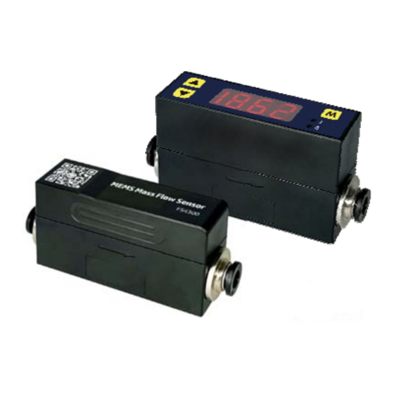
Figure 2.1: FS4308 flow sensor Figure 2.2: MF4308 flow meter Figure 2.3: data cable Please check immediately for the integrity of the product as well as the power and data cable, if any abnormal is identified, please notify the distributor/sales representative or manufacturer as soon as you can. If any defects are confirmed, an exchange shall be arranged immediately via the original sales channel. (Note: the LED display shall not be lit up until the power cable is plugged in). This user manual shall also either be included in the packing box or via an online request for an electronic version. In most cases, this manual shall be made available to the customer before the actual order. The standard cable has an AMPMODU MTE (5 positions) compatible connector with a length of 0.5 meters. www.Siargo.com MF / FS4308 User Manual 6 | P a g e ... -
Page 8: Knowing The Products
Definition 1 Blue RS485B (‐) / SDA, I C data 2 Green Analog output, 1.0 ~ 5.0 Vdc 3 Red Power supply, 8 ~ 24 Vdc 4 Black Ground 5 Yellow RS485A (+) / SCL, I C clock Figure 3.2: MF/FS4308 connection and cable Note: 1. The standard cable has an AMPMODU MTE (5 positions) compatible connector with a length of 0.5 meters. 2. The product offers two digital communications as options, I C or RS485 that can be selected at the time of order. These two communication protocols share the ports as defined in Table 3.1. For the detailed protocols of the corresponding option, please refer to Section 5. 3. The RS485 Modbus is asynchronous, half‐duplex communication. When the data are transmitted or received from the product, the other pin is serving as the ground. www.Siargo.com MF / FS4308 User Manual 7 | P a g e ... -
Page 9: Mechanical Dimensions
3.3. Mechanical dimensions Figure 3.3: FS4308 dimensions with BSPT (R1/4”) connectors. 8mm One‐touch 6mm One‐touch 4mm One‐touch Figure 3.4: FS4308 dimensions with one‐touch connectors. www.Siargo.com MF / FS4308 User Manual 8 | P a g e ... - Page 10 Figure 3.5: MF4308 dimensions with BSPT (R1/4”) connectors. 8mm One‐touch 6mm One‐touch 4mm One‐touch . Figure 3.6: MF4308 dimensions with one‐touch connectors. Note: * Other threads or compressive types can be customized. www.Siargo.com MF / FS4308 User Manual 9 | P a g e ...
-
Page 11: Installation
(i.e., 8 ~ 24 Vdc) and power supply polarization. If an adapter is used, make sure the adapter meets industrial standards and has all safety certifications. Alternatively, this product can also be powered by a 9Vdc battery. f) For the data communication wire connection, please follow the description in Table 3.1 and make sure that the wires are correctly connected to the proper ports on your data device/equipment. Please make sure the data cable meets industrial standards with proper shielding. g) Once the external power is successfully connected, for the MF serial of meters, the LED should be lighted up with the proper information displayed. h) Slowly open the valve(s) of the gas supply if any, upstream or downstream, or both of the pipelines. the product should then start to measure the flow in the pipeline. Note: because the meter has a large dynamical measurement range, it could be normal if you see the small instant www.Siargo.com MF / FS4308 User Manual 10 | P a g e ... - Page 12 flow rate even if there is “no flow” in the pipeline. If the value is consistently present, double‐ check the pipe leakage and then reset the offset if you are sure there is no leakage or flow. h) This will conclude the installation. Cautions a) Don't alter any parts of the product. b) Ensure the electrical connection is properly done per the instructions. c) Make sure no mechanical stresses in the connections. d) The strong electromagnetic interference sources close by or any mechanical shocks at the pipeline may also create malfunctioning of the product. e) Slowly open/close valves at the gas supply piping to prevent abrupt pulse flow impact. www.Siargo.com MF / FS4308 User Manual 11 | P a g e ...
-
Page 13: Operation And Menu Description
Section 7. Be cautious that standard electrical device precautions such as EDS (electrostatic discharge) and DC voltage are observed. Excessive electrostatic discharge may damage the product. The manufacturer‐supplied power and data cable have a locking fixture. Lock the cable and make sure it is properly engaging and will not be accidentally got unplugged. Half‐duplex RS485 Modbus or I C is used for digital data communication. Make sure the wires are properly connected to the receiver side. www.Siargo.com MF / FS4308 User Manual 12 | P a g e ... -
Page 14: Meter Display And Menu Descriptions
“standard liter” (SL), and the maximum can be 99,999,999 SL. The first four digits of the accumulated flow rate are indicated by the “I” LED light, and the last four digits are represented when the “II” LED light is on. The “I” and “II” LED lights will be automatically switched when the accumulated flow rate is displayed. The accumulated flow rate will be automatically saved every three minutes. At the time of the power failure or cut‐off, the value will be representing the latest saved ones. 5.4.2 MENU function input sequence At the flow measurement (main) display, press the three MEMU keys, it will allow the user to perform a variety of settings of the product. The following graph details the key sequence for each function, and some detailed explanations are followed after the graphic presentation. www.Siargo.com MF / FS4308 User Manual 13 | P a g e ... - Page 15 Figure 5.2: MF4308 menu flow chart www.Siargo.com MF / FS4308 User Manual 14 | P a g e ...
- Page 16 20 / 50 / 100 5. 25 / 50 / 100 / Set the display refresh rate 200 Set the upper flow rate alarm Available: 0 ~ 110, means of 0% ~ 110% 6. 0 … 110 full scale. The default value is 100 (100% full scale). Set the lower flow rate alarm Available: 0 ~ 110, means of 0% ~ 110% 7. 0 … 110 full scale. The default value is 0 (0% full scale). 8. 0 / 1 / 2 / 3 Set the display decimal Set the communication baud rate Available: 48, 96, 192, 384, means of baud 9. 48/ 96/192/384 rate 4800, 9600, 19200, 38400. The default value is 384 (baud rate 38400). Set the GCF (gas conversion factor) Available: 10 ~ 999, means of GCF = 100 ~ A. 10 … 999 9990. Default value is 100, means of GCF = 1000. Set the accumulated flow rate unit: b. 0 / 1 b. 0 ‐ SL, b. 1 ‐ Nm . Note: During this process, the meter will continue to measure the flow without being interrupted. www.Siargo.com MF / FS4308 User Manual 15 | P a g e ...
-
Page 17: Detailed Descriptions Of The Functions
3) Set the Modbus address of the meter Use this function to set the RS485 Modbus address of the meter. This setting can also be done via the RS485 communication. 4) Set the response time Use this function to change the response time of the meter. The default one is 10 msec. Increasing the response time will allow more data to average and output a stabler flow rate if the actual flow rate may have some undesired fluctuation. Available response time is 10 msec (4. 1); 20 msec (4. 2); 50 msec (4. 5); 100 msec (4. 10); 200 msec (4. 20); 500 msec (4. 50), and 1000 msec (4.100) www.Siargo.com MF / FS4308 User Manual 16 | P a g e ... - Page 18 8) Set the display decimal The user can use this function to alter the default decimal display. Options are listed below for each flow range: Table 5.2: decimal options Flow range Decimal options 0 ~ 10, 20, 30, 40, 50 SLPM 0, 1, 2 9) Set the communication baud rate This function allows a MENU entry of the RS485 communication baud rate. 10) Set the GCF (the gas conversion factor) The meter is normally calibrated with air at 20°C and 101.325 kPa. When the user wants to set the standard conditions other than the specified temperature or applies the meter for other allowable gases (please contact the manufacturer for the list of gases), it is possible to use this gas conversion factor function to ensure the readings are correct and desired. The default value of the GCF is 1000 (1.000). For example, if one wants to alter the standard temperature to 0°C, the factor can be calculated using the gas equation: PV/T = constant: www.Siargo.com MF / FS4308 User Manual 17 | P a g e ...
-
Page 19: Rs485 Modbus Communication Protocol
11) Set the accumulated flow rate unit. The accumulated flow rate unit can be set to SL or Nm . 5.5 RS485 Modbus communication protocol The digital communication protocol is based on the standard Modbus RTU Half plex mode communication protocol. A master (PC or PLC) can communicate with multiple slaves (the current product) for data exchange and communication parameter configuration. Refer to Table 3.2 for the cable connection. 5.5.1 Hardware connection The RS485 hardware layer is TIA/EIA‐485‐A, as illustrated below. In this configuration, the product (MF/FS4308) is a slave. Figure 5.3: RS485 hardware www.Siargo.com MF / FS4308 User Manual 18 | P a g e ... -
Page 20: Communication Parameters
Address Function codes Data CRC Stop_bits T1‐T2‐T3‐T4 8 bit 8 bit N 8 bit (20≥n≥0) 16 bit T1‐T2‐T3‐T4 Start_bits: 4 periods bit time, for a new frame. Address: The address can be set from 1 to 247 except for 157 (0x9d). 0 is the broadcast address. Function codes: Define the product's functions/actions (slaves), either execution or response. Data: The address of the register, length of data, and the data themselves. CRC: CRC verification code. The low byte is followed by the high byte. For example, a 16‐bit CRC is divided into BYTE_H and BYTE_L. In the framing, the BYTE_L will come first, then followed by the BYTE_H. The last one is the STOP signal. Stop_bits: 4 periods bit time, for ending the current frame. www.Siargo.com MF / FS4308 User Manual 19 | P a g e ... -
Page 21: Function Codes
0x0040 40065 (0x0040) Baud rate Communication baud rate (R/W) 0x0082 40131 (0x0082) GCF * Gas conversion factor (R/W) 0x008B 40140 (0x008B) Digital filter depth * Response time or sampling time (R/W) 0x008C 40141 (0x008C) Upper flow alarm * Upper flow rate limit alarm (R/W) 0x0098 ~ 0x0099 40153 (ox0098) Lower flow alarm * Lower flow rate limit alarm (R/W) 0x009A ~ 0x009B 40155 (ox009A) Offset calibration * Offset reset or calibration (W) 0x00F0 40241 (0x00F0) Write protection Write protection of selected parameters (W) 0x00FF 40256 (0x00FF) Notes: 1, R – Read‐only, W – Write only, R/W – Read and write. 2, For the * marked functions, please disable the write protection before executing the command. www.Siargo.com MF / FS4308 User Manual 20 | P a g e ... - Page 22 0x003C ~ 0x003E Totalizer Read Y Description Accumulated or totalized flow rate Value type UINT 32 + UNIT 16 Accumulated flow rate = Value (0x003C) * 65536 + Value (0x003D) + Value (0x003E)/1000 e.g., for an accumulated flow rate of 3452.245 m , the user will read “0 Notes (0x0000)” from register 0x003C; “3452 (0x0D7C)” from register 0x003D, and “245 (0x00F5)” from register 0x003E. Then, the accumulated flow rate = 0 + 3425 + 245/1000 = 3425.245. Write N 0x0040 Temperature Read Y Description Gas temperature. Value type UINT 16 Ambient temperature = Value (0x0040) / 100 e.g., for a gas temperature of 23.45 °C, the user will read “2345 (0x0929)” Notes from register 0x0040, therefore Ambient temperature = 2345/100 = 23.45 www.Siargo.com MF / FS4308 User Manual 21 | P a g e ...
- Page 23 Write Y Alarm: Flow rate upper 0x0098 ~ 0x0099 limited Read Y Description Set alarm value for an upper flow rate limit Value type UINT 32 Alarm values = Value (0x0098)*65536 + Value (0x0099) Notes When the flow rate is above a set value, an alarm will be triggered. Notes: please disable the write protection before executing this command. Alarm: Flow rate lower Write Y 0x009A ~ 0x009B limit Read Y Description Set alarm value for a lower flow rate limit Value type UINT 32 Alarm values = Value (0x009A)*65536 + Value (0x009B) Notes When the flow rate is below a set value, an alarm will be triggered. Notes: please disable the write protection before executing this command. www.Siargo.com MF / FS4308 User Manual 22 | P a g e ...
- Page 24 Reset or calibrate the offset Value type UINT 16, Fixed value 0xAA55 To reset or calibrate the offset, write 0xAA55 to register 0x00F0. Notes: Notes 1. When you execute this command, make sure there is NO flow in the flow channel. 2. Please disable the write protection before executing this command. Write Y 0x00FF Write protection Read N Description Write protection disabler for a set value to a specific register. Value type UINT 16, Fixed value 0xAA55 This function is enabled at the time of product shipment. To enable the write function of a specific parameter, such as GCF, or offset, the user needs to send Notes 0xAA55 to the register 0x00FF, and then the write function will be enabled (write protection is disabled). After the write execution is completed, the firmware will automatically re‐enable the write protection. www.Siargo.com MF / FS4308 User Manual 23 | P a g e ...
-
Page 25: I 2 C Communication Protocol
5.6 I C communication protocol 5.6.1 I C interface connection diagram 5.6.2 I C interface read/write sequences www.Siargo.com MF / FS4308 User Manual 24 | P a g e ... -
Page 26: I 2 C Interface Command Description
The 8‐bit CRC checksum transmitted after each two data bytes (int 16) is generated by a CRC algorithm. Its properties are listed in the table below. To calculate the checksum, only these two previously transmitted data bytes are used. Property Value Name CRC‐8 Protected data C read and write Width 8 bits Polynomial 0x07 (x8 + x2 + x + 1) Initialization 0x00 Reflect input False Reflect output False Final XOR 0x00 Example CRC(0x4E20) = 0x6D www.Siargo.com MF / FS4308 User Manual 25 | P a g e ... -
Page 27: Analog Output (1.0 ~ 5.0 Vdc)
(SLPM) 0.0 0 0 0 0 10.0 70 120 150 420 20.0 200 390 530 1450 30.0 380 760 1100 2900 40.0 620 1250 1860 4600 50.0 920 1850 2810 6500 Figure 5.5: MF/FS4308 pressure loss www.Siargo.com MF / FS4308 User Manual 26 | P a g e ... -
Page 28: Product Selection And Order Information
6. Product selection and order information The product part number is composed of the product model number and suffixes indicating the full‐ scale flow rate, as well as the other parameters. Refer to the following for details. MF/FS4308 ‐ ‐ ‐ ‐ Gas (A – air; N2, O2, Ar; B – N O; C – CO ); for other gases, please contact the manufacturer. Output: B – RS485; E – I C; V – analog 1.0 ~ 5.0 Vdc. Option: V, BV or EV. Mechanical connection: R – R 1/4”; O4/O6/O8 one‐touch Maximum full scale flow rate (for the value refer to the table below). If the unit is not SLPM, the unit needs to be specified here. www.Siargo.com MF / FS4308 User Manual 27 | P a g e ... -
Page 29: Technical Specifications
Max. overflow 200 SLPM Max. flow change 30 SLPM/sec Electrical connector AMPMODU MTE 5 positions MENU access (MF serial) 3 key – front face keyboard/digital Instant flow rate, totalizer, or accumulated Display (MF serial) flow rate with LED & 2 indicators Mechanical connection R 1/4”, One‐touch or customized Protection IP40 Storage temperature ‐20 ~ 70 °C Fluid compatibility Non‐corrosive CE EN61000‐2; ‐3; ‐4 RoHS/REACH Certified www.Siargo.com MF / FS4308 User Manual 28 | P a g e ... -
Page 30: Technical Notes For The Product Performance
Another key point to comparing the different flow meters is that as long as the fluidic flow is a continuous flow without pulsation, then the fluidic dynamic will have the system following the Bernoulli equation: www.Siargo.com MF / FS4308 User Manual 29 | P a g e ... -
Page 31: Particle Contamination And Fluidic Cleanness
Therefore, measurement by the meter for a gas medium other than the calibration gas would bear larger measurement errors, particularly at the low Reynold number range where the laminar flow has a sensitive flow profile. www.Siargo.com MF / FS4308 User Manual 30 | P a g e ... -
Page 32: Troubleshooting
Phenomena Possible causes Actions The power is not connected; Connect the power, check the the battery is empty cable Cable connection incorrect Check cable No signal / display No flow or clogging Check flow and contamination Power regulator failure Return to factory Sensor failure Return to factory Large errors or unexpected Particles, fluid type Check system flow rate Erroneous or large noise Vibration, unstable flow Check system Offset unstable Circuitry instability Check the system, power off No digital interface Wrong address, software Check commands, connection www.Siargo.com MF / FS4308 User Manual 31 | P a g e ... -
Page 33: Warranty And Liability
Siargo and its officers, employees, subsidiaries, affiliates, and sales channels harmless against all claims, costs, damages, and expenses or reasonable attorney fees from direct or indirect sources. Siargo makes no other warranty, express or implied, and assumes no liability for any special or incidental damage or charges, including but not limited to any damages or charges due to installation, dismantling, reinstallation, etc. other consequential or indirect damages of any kind. To the extent permitted by law, the exclusive remedy of the user or purchaser, and the limit of Siargo's liability for any and all losses, injuries, or damages concerning the products, including claims based on contract, negligence, tort, strict liability, or otherwise shall be the return of products to Siargo, and upon ... - Page 34 (2) Products that have been subject to chemical attacks, including exposure to corrosive substances or contaminants. In the case of battery usage, long‐term discharge, or leakage‐ induced damages; (3) Products that have been opened or dismantled for whatever reasons; (4) Products that have been subject to working conditions beyond the technical specification as described by this manual or related datasheet published by the manufacturer; (5) Any damages incurred by the incorrect usage of the products; (6) Siargo does not provide any warranty on finished goods manufactured by others. Only the original manufacturer's warranty applies; (7) Products that are re‐sold by unauthorized dealers or any third parties. www.Siargo.com MF / FS4308 User Manual 33 | P a g e ...
-
Page 35: Service/Order Contact And Other Information
RMA on the returned package or include a letter with the RMA information. Direct customer service request(s) should be addressed to Sales Representative Europe: IDENTIC GmbH In der Siedlerruh 24 69123 Heidelberg / Germany Phone: +40-(0)6221-7509777 Email: info@identic.de www identic.de . For further information and updates, please visit www.Siargo.com MF / FS4308 User Manual 34 | P a g e ... -
Page 36: Appendix I: Product Evaluation Kit
The USB Cable to connect cable connected to the PC is also included. to the product For most of the products, the power from the PC via the USB cable will be sufficient to power the sensor product, no external power will be USB cable to required. However, for multiple sensors in serial, connect to PC the power via the USB cable may not be enough, an external power adapter with 8 ~ 24 Vdc will External power be required. adapter (optional) www.Siargo.com MF / FS4308 User Manual 35 | P a g e ... -
Page 37: Appendix Ii: Document History
Appendix II: Document history Revision A.0 (August 2022) Preliminary release. www.Siargo.com MF / FS4308 User Manual 36 | P a g e ...
Need help?
Do you have a question about the Thermal-D MF/FS4308 Series and is the answer not in the manual?
Questions and answers