Table of Contents
Advertisement
Quick Links
Advertisement
Table of Contents

Related Manuals for Siargo MF5100V


Summary of Contents for Siargo MF5100V
- Page 1 Gas Mass Flow Meter VB.1 Model MF5100V ...
- Page 2 User Manual Document No. 07‐2021‐MC2 EN Issue date: 2021.07 Revision: VB.1 Siargo Ltd. 3100 De La Cruz Boulevard, Suite 210 Santa Clara, CA 95054 USA Tel: +1(408)969.0368 Email: info@siargo.com © Copyright 2021 by Siargo Ltd. Siargo Ltd. and its subsidiaries reserve the right to change the specifications and/or descriptions without prior notice. For further information and updates, please visit: www.Siargo.com www.Siargo.com MF5100V User Manual 1 | P a g e ...
- Page 3 Only the trained or qualified personnel shall be allowed to perform product services. Use with caution! Be cautious for the electrical safety, even it operates at a low voltage, or battery, any electrical shock might lead to some unexpected damages. The gas to be measured should be clean and free of particles. Do not apply this meter for liquid medium. Do not apply for any unknown or non‐specified gases that may damage the product. For remote data, please be sure the meter is properly configured. www.Siargo.com MF5100V User Manual 2 | P a g e ...
-
Page 4: Table Of Contents
Starting the measurement ................... 14 6.6 RS485 Modbus communication protocol ............... 15 6.6.1 Hardware connection .................... 15 6.6.2 Communication parameters .................. 15 6.6.3 Frame .......................... 16 6.6.4 Function codes ...................... 16 6.6.5 Registers ........................ 17 7. Product selection and order information............ 2 0 7.1 Product selection .................... 20 7.2 Order contact and customer support .............. 20 8. Technical specifications ................ 2 1 www.Siargo.com MF5100V User Manual 3 | P a g e ... - Page 5 2 9.1 Measurement principle .................. 22 9.2 Precautions for the best performance of the product .......... 22 9.2.1 Comparison with a third party reference meter ............... 22 9.2.2 Particle contamination and fluidic cleanness .............. 23 9.2.3 Apply to a different gas medium .................. 23 10. Troubleshooting .................. 2 4 11. Warranty and Liability ................ 2 5 12. Service contact .................. 2 7 Appendix I: Product evaluation kit .............. 28 Appendix II: Document history .............. 29 www.Siargo.com MF5100V User Manual 4 | P a g e ...
-
Page 6: Overview
Applications of the products include laboratory gas processing, cylinder gas control in a mobile vehicle such as an ambulance, and many more. The meters are operated with Siargo’s proprietary MEMS calorimetric mass flow sensors together with the smart control electronics. The sensor surface is passivated with silicon nitride ceramic materials together with a water/oil proof nano‐coating for performance and reliability. The meter body is made of stainless steel that is available for applications of most of the gases. www.Siargo.com MF5100V User Manual 5 | P a g e ... -
Page 7: Receipt / Unpack Of The Products
The power adapter and/or data cable as shown below may also be found according to your actual order. Flow meter data cable, optional Figure 2.1: MF5100V flow meter and accessories Please check immediately for the integrity of the product as well as the power and data cable, if any abnormal is identified, please notify the distributor/sales representative or manufacturer as soon as you can. If any defects are confirmed, an exchange shall be arranged immediately via the original sales channel. (Note: the LCD screen shall not be lighted until the power cable is plugged in or the battery is installed). This user manual shall also either be included in the packing box or via an online request for an electronic version. In most cases, this manual shall be made available to the customer before the actual order. The optional cable is a standard one with a locking connector that offers external power as well as wired data communication. For the battery, the recommended lithium‐ion battery (Tadiran TL 5930 or SAFT LS33600, both are 3.6Vdc, 19Ah) shall be purchased by the user at a local supply due to the freight restrictions. www.Siargo.com MF5100V User Manual 6 | P a g e ... -
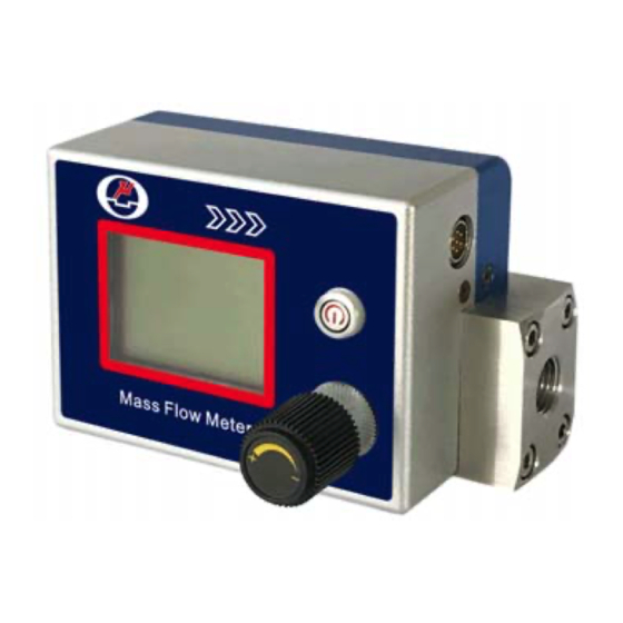
Page 8: Knowing The Products
Figure 3.2: MF5100V LCD display The LCD provides all information that the product measures. Some symbols are reserved for future upgrades, and will not be lighted during the operation. The following table details the meaning of each of the symbols. www.Siargo.com MF5100V User Manual 7 | P a g e ... -
Page 9: Power And Data Cable Description
1 Red Power supply, 8~24 Vdc 2 Black Ground 3 Green RS485 A 4 Brown RS485 B 5 Yellow Alarm 6 Transparent Ground 7 Violet N.C. Figure 3.3: MF‐GD interface terminal The cable connector has two pins for positioning when plugging into the meter. Do not force the plug. After the plug is properly engaged, use the plug screw to tighten the engagement. www.Siargo.com MF5100V User Manual 8 | P a g e ... -
Page 10: Mechanical Dimensions
3.4. Mechanical dimensions Figure 3.4: MF5100V meter dimensions The mechanical dimensions shown are for up to 0~5 SLPM flow rate. For another flow rate, please contact the manufacturer for detailed information. www.Siargo.com MF5100V User Manual 9 | P a g e ... -
Page 11: Battery Installation
4. Battery installation For the battery power options, please refer to the following graph to install a battery (C‐Cell lithium battery with 3.6Vdc and 9 Ah). The battery should have the necessary safety certificate. Following the steps to install the battery: (a) Removal of the screws with a screwdriver, 4 screws as indicated by the red arrows: T2 (M2.5) Figure 4.1: Removal of screws (b) Install the battery – for most of the applications, the battery life should be 3+ years. And re‐ assemble the back cover of the meter head. Figure 4.2: Install the battery www.Siargo.com MF5100V User Manual 10 | P a g e ... -
Page 12: Meter Installation
Please make sure the data cable meets industrial standards with proper shielding. f) Once the external power is successfully connected or the battery is installed, the LCD should be lighted up with the proper information displayed works correctly. g) Slowly open the valve(s) if any, upstream or downstream or both of the pipeline, followed by slowly open the manual control valve on the meter. And the meter should then start to measure the flow in the pipeline. Note: because the meter has a large dynamical measurement range, it could be normal if you see the small instant flow rate before you open the valve as there could be some leakage. However, make sure the meter reads null when there is no flow present in the pipeline. h) This will conclude the installation. www.Siargo.com MF5100V User Manual 11 | P a g e ... - Page 13 Cautions a) Don't alter any parts of the product. b) Ensure the electrical connection is properly done per the instructions. c) Make sure no mechanical stresses in the connections. d) The strong electromagnetic interference sources close by or any mechanical shocks at the pipeline may also create malfunctioning of the product. e) Slowly open/close valves to prevent abrupt pulse flow impact. www.Siargo.com MF5100V User Manual 12 | P a g e ...
-
Page 14: Operation
EDS (electrostatic discharge) and DC voltage are observed. Excessive electrostatic discharge may damage the product. Use the power switch to switch off the power when it is operating with the battery and it will be idle for a longer period for the ultimate optimizing the battery power. Otherwise, although the meter is configured with low power operation, at idle status, the meter will attempt to detect the flowrate from time to time to ensure all data can be properly registered. www.Siargo.com MF5100V User Manual 13 | P a g e ... -
Page 15: Control The Flowrate With The Manual Valve
The manufacturer‐supplied power and data cable have a locking fixture. Lock the cable and make sure it is properly engaging and will not be accidentally got unplugged. Half‐duplex RS485 Modbus is used for digital data communication. Make sure the wires are properly connected at the receiver side. 6.4 Control the flowrate with the manual valve The manual control of the precise flow rate is via the mechanical valve with a 16 turn high precise from fully close to fully open, as long as it is within the specified pressure. Turn the valve slowly for the desired control values. Be careful with the particle contamination that may jam the valve passage leading to control failures. 6.5 Starting the measurement Once the power is supplied (either via battery or external DC power) and no abnormal issues are observed, the meter is ready to perform the measurements. The default display is for the mass flow measurement having two numerical lines on the LCD. The middle line is the totalizer or accumulated flow rate, and the lower line is the instant flow rate. The upper line shows the temperature, meter address, and battery status. www.Siargo.com MF5100V User Manual 14 | P a g e ... -
Page 16: Rs485 Modbus Communication Protocol
PLC) can communicate with multiple slaves (the current product) for data exchange and communication parameter configuration. Refer to Table 3.3 for cable connection. 6.6.1 Hardware connection The hardware layer is TIA/EIA‐485‐A, as illustrated below. In this configuration, the product (MF5100) is a slave. 6.6.2 Communication parameters The PC UART communication parameters are listed in the following table. Protocol Parameters RTU Baud rate (Bits per second) 9600 bps Start bits 1 Data bits 8 Stop bits 1 Even/Odd parity None Bits period 104.2 µsec Bytes period 1.1458 msec Maximum data length 20 Maximum nodes 247 www.Siargo.com MF5100V User Manual 15 | P a g e ... -
Page 17: Frame
The Modbus function codes applied for the product are the sub‐class of the standard Modbus function‐codes. These codes are used to set or read the registers of the product: Code Name Functions 0x03 Read register Int, char, float Read register(s) 0x06 Set single register Int, char, float Write one single 16‐bit register 0x08 CRC verification Int Verify the communication 0x10 Set multiple registers Int, char, float Write multiple registers www.Siargo.com MF5100V User Manual 16 | P a g e ... -
Page 18: Registers
40256 (0x00FF) The detailed information of each register is described below: Y: enabled; N: disabled Write Y Address 0x0081 Read Y Description Address of the product Value type UINT 16 Notes Values from 1 to 247 except for 157 (0x9d). 0 is the broadcast address. Write N Serial number, SN 0x0030…0x0035 Read Y Description Series Number of the product, SN Value type UINT 8 (12bits) SN= value(0x0030), value(0x0031),….,value (0x0035); Notes Receiving 12 bits as: 2A 47 37 41 45 49 30 32 30 35 38 2A , the corresponding Serial Number is *G7AEI02058*. www.Siargo.com MF5100V User Manual 17 | P a g e ... - Page 19 Value type UINT 16 Maximum flow rate limit =(Value(oxoo85)*65536+Vlaue(0x0086))/1000 e.g.: to set a maximum flow rate limit of 30 SLPM, write o to register 0x0085, Notes and write 30000 to register 0x0086. Then the value will be (0*65536+30000)/1000 = 30 Write Y GCF 0x008B Read Y Description The gas conversion factor for using with gas different from calibration gas Value type UINT 16 The air (default) is 1000, normally read from register 0x008B. The product will disable this function with write protection once the Notes metering gas is confirmed with the proper GCF. For a specific GCF value, please contact the manufacturer. Write Y GC_gas 0x53 Read Y Description This value is assigned for a specific gas at the time of order Value type UINT 16 www.Siargo.com MF5100V User Manual 18 | P a g e ...
- Page 20 Y Pulse 0x93 Read Y Description Set the pulse rate for totalized flow rate Value type UINT 16 The default value is 100 or 10mL/pulse. Available values are: 1=0.1mL; 10=1 mL; 100=10mL; 1000=100mL; and 10000=1000mL (1L) per Notes pulse. Write Y Write protection 0x00FF Read N Description Write protection disabler for a set value to a specific register. Value type Unsigned int, Fixed value 0xAA55 This function is enabled at the time of product shipment. To enable the write function of a specific parameter, such as GCF, the user needs to send 0xAA55 to the register 0x00FF, and then the write function will be enabled (write Notes protection is disabled). After the write execution is completed, the firmware will automatically re‐enable the write protection. Only Address will not be write‐protected. www.Siargo.com MF5100V User Manual 19 | P a g e ...
-
Page 21: Product Selection And Order Information
1/4” 0.3~30 MF5108V 8.0 3/8” 0.5~50 7.2 Order contact and customer support The sales offices and the sales distributors/representatives are listed at the end of this document. For small quantities, the order can be placed either through the Siargo website: www.siargo.com or the sales office. For large quantities, please contact the sales office, distributors, or sales representatives. Siargo is making every effort to ensure the quality of the products. In case of questions and/or product supports, please contact the customer service listed at the end of the document. www.Siargo.com MF5100V User Manual 20 | P a g e ... -
Page 22: Technical Specifications
Digital output RS485 Modbus half‐duplex Display LCD Mechanical connection NPT or customized Gas ID 2 or more gases Storage temperature ‐20 ~ 70 °C Reference conditions 20°C, 101.325 kPa, air Fluid compatibility Non‐corrosive CE EN61326‐1; ‐2; ‐3 Note: 1. For other features or specifications not listed, please contact the manufacturer. 2. All specifications listed in the following table unless otherwise noted apply for calibration conditions at 20°C and 101.325 kPa absolute pressure with air. The product is horizontally mounted at the time of calibration. 3. The manual valve has a high precision of 16 turns. www.Siargo.com MF5100V User Manual 21 | P a g e ... -
Page 23: Technical Notes For The Product Performance
Another key point to compare the different flow meter is that as long as the fluidic flow is a continuous flow without pulsation, then the fluidic dynamic will have the system following the Bernoulli equation: www.Siargo.com MF5100V User Manual 22 | P a g e ... -
Page 24: Particle Contamination And Fluidic Cleanness
The meter operates similar to the principle described in the international standard for thermal mass flow meters (ISO 14511:2001 ‐ Measurement of fluid flow in closed conduits — Thermal mass flowmeters). By measuring the gas thermal conductivity and thermal capacitance, the technology allows the meter to identify any gases with distinct thermal parameters, and therefore, it will be able to automatically switch the pre‐calibrated data for the correct gas measurement. For further information, please contact the manufacturer. www.Siargo.com MF5100V User Manual 23 | P a g e ... -
Page 25: Troubleshooting
Cable connection incorrect Check cable No signal / display No flow or clogging Check flow and contamination Power regulator failure Return to factory Sensor failure Return to factory Large errors or unexpected Particles, fluid type Check system flow rate Erroneous or large noise Vibration, unstable flow Check system Valve not work Wire connection, valve Return to factory Offset unstable Circuitry instability Check system, power off No digital interface Wrong address, software Check commands, connection No wireless, BT cannot pair Wrong model, data jam Check model, power off/on www.Siargo.com MF5100V User Manual 24 | P a g e ... -
Page 26: Warranty And Liability
Siargo makes no warranty, representation, or guarantee and shall not assume any liability regarding the suitability of the products described in this manual for any purposes that are not specified in this manual. The users shall be held for full responsibility for validating the performance and suitability of the products for their particular design and applications. For any of the misusage of the products out of the scope described herein, the user shall indemnify and hold Siargo and its officers, employees, subsidiaries, affiliates, and sales channels harmless against all claims, costs, damages, and expense or reasonable attorney fee from direct or indirect sources. Siargo makes no other warranty, express or implied, and assumes no liability for any special or incidental damage or charges, including but not limited to any damages or charges due to installation, ... - Page 27 (2) Products that have been subject to chemical attacks, including exposure to corrosive substances or contaminants. In the case of battery usage, long term discharge or leakage induced damages; (3) Products that have been opened or dismantled for whatever reasons; (4) Products that have been subject to working conditions beyond the technical specification as described by this manual or related datasheet published by the manufacturer; (5) Any damages incurred by the incorrect usage of the products; (6) Siargo does not provide any warranty on finished goods manufactured by others. Only the original manufacturer's warranty applies; (7) Products that are re‐sold by unauthorized dealers or any third parties. www.Siargo.com MF5100V User Manual 26 | P a g e ...
-
Page 28: Service Contact
12. Service contact Siargo Ltd. is making every effort to ensure the quality of the products. In case of questions, and or product supports, please contact customer service at the address listed below. We will respond to your request in a timely fashion and will work with you toward your complete satisfaction. Customer service and all orders should be addressed to Siargo Ltd. 3100 De La Cruz Boulevard, Suite 210, Santa Clara, California 95054, USA Phone: +01(408)969‐0368 Email: info@Siargo.com For orders, please provide an accurate and full postal address. Siargo will not ship to P.O. Boxes or via a third party. For further information and updates, please visit www.Siargo.com. www.Siargo.com MF5100V User Manual 27 | P a g e ... -
Page 29: Appendix I: Product Evaluation Kit
Each converter has a fixed cable that can be directly connected to the product. The USB Cable to connect cable connected to the PC is also included. to the product For most of the product, the power from the PC via the USB cable will be sufficient to power the sensor product, no external power will be USB cable to required. However, for multiple sensors in serial, connect to PC the power via the USB cable may not be enough, an external power adapter with 8~24Vdc will be External power required. adapter (optional) www.Siargo.com MF5100V User Manual 28 | P a g e ... -
Page 30: Appendix Ii: Document History
Appendix II: Document history Revision B.1 (July 2021) Corrections. Revision B.0 (March 2021) Reformat, corrections, add the evaluation kit. …… Revision A.0 (November 2018): First release. Sales Europe: IDENTIC GmbH In der Siedlerruh 24 69123 Heidelberg / Germany Phone: +49 6221 7509 777 Email: info@identic.de www.Siargo.com MF5100V User Manual 29 | P a g e ...
Need help?
Do you have a question about the MF5100V and is the answer not in the manual?
Questions and answers