Table of Contents
Advertisement
Quick Links
Operating Manual
Translation of the original operating manual
KT (E6.1)
Cooling Incubator
with Peltier Refrigerating Technology and program controller
Model
KT 53
KT 53-UL
KT 115
KT 115-UL
KT 170
KT 170-UL
BINDER GmbH
Address: Post office box 102, 78502 Tuttlingen, Germany Phone: +49 7462 2005 0
Fax: +49 7462 2005 100 Internet: http://www.binder-world.com
E-mail: info@binder-world.com Service Hotline: +49 7462 2005 555
Service Fax: +49 7462 2005 93 555 Service E-Mail: customerservice@binder-world.com
Service Hotline USA: +1 866 885 9794 or +1 631 224 4340 x3
Service Hotline Asia Pacific: +852 390 705 04 or +852 390 705 03
Service Hotline Russia and CIS: +7 495 988 15 16
Issue 10/2021
Model version
KT053-230V
KT053UL-120V
KT115-230V
KT115UL-120V
KT170-230V
KT170UL-120V
Art. No.
9020-0311
9020-0312
9020-0313
9020-0314
9020-0289
9020-0310
Art. No. 7001-0291
Advertisement
Table of Contents
Troubleshooting

Related Manuals for Binder KT E6.1


Summary of Contents for Binder KT E6.1
- Page 1 Fax: +49 7462 2005 100 Internet: http://www.binder-world.com E-mail: info@binder-world.com Service Hotline: +49 7462 2005 555 Service Fax: +49 7462 2005 93 555 Service E-Mail: customerservice@binder-world.com Service Hotline USA: +1 866 885 9794 or +1 631 224 4340 x3 ...
-
Page 2: Table Of Contents
Contents SAFETY ........................6 Personnel Qualification ........................6 Operating manual ..........................6 Legal considerations ........................... 6 1.3.1 Intellectual property ........................7 Structure of the safety instructions ...................... 7 1.4.1 Signal word panel ........................7 1.4.2 Safety alert symbol ........................8 1.4.3 Pictograms .......................... - Page 3 SET-POINT ENTRY IN “FIXED VALUE” OPERATING MODE ......35 Setting ranges: ..........................35 Entering the set-points via “quick menu” ................... 36 Entering the set-points via general menu ..................37 TIME PROGRAMS ....................39 Starting and running an existing time program ................. 40 Cancelling a running time program ....................
- Page 4 21.1 General information, personnel qualification................... 108 21.2 Maintenance intervals, service ......................109 21.3 Simple troubleshooting ........................109 21.4 Sending the chamber back to BINDER GmbH ................112 22. DISPOSAL......................112 22.1 Disposal of the transport packing ....................112 22.2 Decommissioning ..........................113 22.3 Disposal of the chamber in the Federal Republic of Germany ............
- Page 5 23.4 KT (E6.1) technical data ........................117 23.5 Equipment and Options (extract) ....................118 23.6 Spare parts and accessories (extract) .................... 119 23.7 KT / KT-UL 53 dimensions ......................120 23.8 KT / KT-UL 115 dimensions ......................121 23.9 KT / KT-UL 170 dimensions ......................122 24.
-
Page 6: Safety
In no event shall BINDER be held liable for any damages, direct or incidental arising out of or related to the use of this manual. -
Page 7: Intellectual Property
All obligations on the part of BINDER derive from the respective purchase contract, which also contains the entire and exclusively valid statement of warranty administration and the general terms and conditions, as well as the legal regulations valid at the time the contract is concluded. -
Page 8: Safety Alert Symbol
1.4.2 Safety alert symbol Use of the safety alert symbol indicates a risk of injury. Observe all measures that are marked with the safety alert symbol in order to avoid death or injury. 1.4.3 Pictograms Warning signs Stability hazard Electrical hazard Hot surface Explosive atmosphere Harmful substances... -
Page 9: Word Message Panel Structure
Figure 1: Position of labels on KT-UL Keep safety labels complete and legible. Replace safety labels that are no longer legible. Contact BINDER service for these replacements. Type plate The type plate is located on the left chamber side, on the bottom, right side. - Page 10 Indications of the type plate (example) Indication Information BINDER Manufacturer: BINDER GmbH KT 170 Model Cooling incubator Device name Serial No. 000000000000 Serial no. of the chamber Built 2021 Year of construction Nominal 100 °C Nominal temperature temperature 212 °F IP protection IP type of protection acc.
-
Page 11: General Safety Instructions On Installing And Operating The Chambers
(for Germany: DGUV guidelines 213-850 on safe working in laboratories, issued by the employers’ liability insurance association). BINDER GmbH is only responsible for the safety features of the chamber provided skilled electricians or qualified personnel authorized by BINDER perform all maintenance and repair, and if components relating to chamber safety are replaced in the event of failure with original spare parts. -
Page 12: Intended Use
The charging material shall not contain any corrosive ingredients that may damage the machine components made of stainless steel, aluminum, and copper. Such ingredients include in particular acids and halides. Any corrosive damage caused by such ingredients is excluded from liability by BINDER GmbH. KT (E6.1) 10/2021... - Page 13 The requirements described in the Operating Manual for installation site and ambient conditions (Chap. 3.4) must be met. WARNING: If customer should use a BINDER chamber running in non-supervised continuous operation, we strongly recommend in case of inclusion of irrecoverable specimen or samples to split such specimen or samples and store them in at least two chambers, if this is feasible.
-
Page 14: Foreseeable Misuse
Foreseeable Misuse Other applications than those described in chap. 1.8 are not approved. This expressly includes the following misuses (the list is not exhaustive), which pose risks despite the inherently safe construction and existing technical safety equipment: • Non-observance of Operating Manual •... -
Page 15: Residual Risks
1.10 Residual Risks The unavoidable design features of a chamber, as well as its proper field of application, can also pose risks, even during correct operation. These residual risks include hazards which, despite the inherently safe design, existing technical protective equipment, safety precautions and supplementary protective measures, cannot be ruled out. -
Page 16: Operating Instructions
• Absence of a plausibility check to rule out erroneous inscription of electrical components • Performance of repair work by untrained/insufficiently qualified personnel • Inappropriate repairs which do not meet the quality standard specified by BINDER • Use of replacement parts other than BINDER original replacement parts •... -
Page 17: Chamber Description
• Cleaning See operating manual chap. 21.3. • Examinations The chamber has been inspected by the “Deutsche Gesetzliche Unfallversicherung e.V. (DGUV) (German Social Accident Insurance (DGUV)” (German Social Accident Insurance (DGUV), Testing and Certification Body Foodstuffs and Packaging Industry in DGUV Test) and bears the GS mark. (Not valid for UL chambers) UL units only: The chamber is certified by Underwriters Laboratories Inc. -
Page 18: Chamber Overview
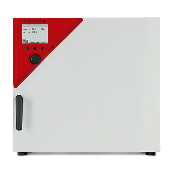
Chamber overview Instrument panel with microprocessor controller T4.12 and USB interface Door handle Chamber door Main power switch Figure 3: Cooling incubator KT (example: model KT 170) Instrument panel 5,7" controller display Context-sensitive buttons USB interface Operating button Pilot lamp: ready for operation Figure 4: Instrument panel with microprocessor controller T4.12 and USB interface KT (E6.1) 10/2021 Page 18/133... -
Page 19: Chamber Rear
Chamber rear Figure 5: Chamber rear with position of options (example KT 170) DIN-socket for zero-voltage relay alarm outputs (option) (not used) DIN socket for analog output 4-20 mA (option) DIN-socket for zero-voltage relay control outputs (option) (not used) Ethernet interface for computer communication Peltier fan grid Socket for IEC connector plug with power cable KT (E6.1) 10/2021... -
Page 20: Completeness Of Delivery, Transportation, Storage, And Location Of Installation
Note on second-hand chambers (Ex-Demo-Units): Second-hand chambers are chambers that were used for a short time for tests or exhibitions. They are thoroughly tested before resale. BINDER ensures that the chamber is technically sound and will work flawlessly. Second-hand chambers are marked with a sticker on the chamber door. Please remove the sticker before commissioning the chamber. -
Page 21: Guidelines For Safe Lifting And Transportation
Permissible ambient temperature range during transport: 10 °C / 14°F to +60 °C / 140°F. You can order transport packing for moving or shipping purposes from BINDER service. Storage Intermediate storage of the chamber is possible in a closed and dry room. Observe the guidelines for temporary decommissioning (chap. - Page 22 Do not install or operate the chamber in potentially explosive areas. DANGER Danger of explosion due to combustible dusts or explosive mixtures in the vicinity of the chamber. Serious injury or death from burns and / or explosion pressure. ∅ Do NOT operate the chamber in potentially explosive areas. ...
-
Page 23: Installation Of The Equipment
With an increased amount of dust in the ambient air, clean the Peltier fan grid (7) by suction or blowing several times a year. Avoid any conductive dust in the ambiance according to the chamber layout complying with pollution degree 2 (IEC 61010-1). -
Page 24: Electrical Connection
• Only use original connection cables from BINDER according to the above specification. UL chambers: Use only a UL Listed Power supply cord (UL category ELBZ), SJT 3x14 AWG (2.08 mm²);... -
Page 25: Start Up
To reduce odors quickly we recommend heating up the chamber to its nominal temperature for one day and in a well-ventilated location. WARNING: If customer should use a BINDER chamber running in non-supervised continuous operation, we strongly recommend in case of inclusion of irrecoverable specimen or samples to split such specimen or samples and store them in at least two chambers, if this is feasible. -
Page 26: Menu Structure
Menu structure Fixed value 08.03.2015 05:05:06 Setpoint Actual value 25.0 25.2 Temperature [°C] 100.0 Initial view (sample values). Press the desired menu button. User Quick menu Menu From the Initial view you have access to different menus using the menu buttons “User”, “Quick menu”, or “Menu”. - Page 27 Fixed value 08.03.2015 05:05:06 ..\ Menu Measurement chart Optional equipment Sensor adjustment General menu (next page) Service contact (“Optional equipment” menu item is visible only with System information optional chamber equipment) Close Home Switching between the operating modes “control off” or “fixed value”, Controller mode chap.
-
Page 28: Quick Menu
6.1.2 Quick menu The Quick menu provides fast access to frequently used functions. Fixed value 08.03.2015 05:05:06 ..\ Quick menu Measurement chart Active alarms Temperature setpoint Fan speed setpoint “Quick menu” Safety controller setpoint Time program Week program Close Home Measurement chart Graphical display of the measured values, chap. -
Page 29: Operating Modes
Operating modes In the “control off” mode (chap. 6.2.1), the controller is non-functional and displays only the actual values. There is no heating or refrigeration. The temperature approximates the ambient value, the fan turns with 40 % speed. You can enter the desired set point values in “fixed value” mode (chap. 8). The controller then operates as a fixed-point control, i.e., it reaches and maintains the defined temperature set-point until the next manual change. - Page 30 Control off 08.03.2015 05:05:06 ..\ Menu Controller mode Event list Alarms General menu with controller mode “Control off”. Setpoints The controller mode “Fixed value” or “Control off” is Safety controller indicated in the display headline. Programs Import/Export Settings Close Home Go back to the initial view with “Home”.
-
Page 31: Performance During And After Power Failure
Submenu “System information” (sample values). Parameter version: 511B-0006-0011 Firmware version (1): 521C-0001-002A Firmware version (2): 521B-0005-001E Close Home To display the BINDER Service contact data, go to Menu > Service contact Fixed value 08.03.2015 05:05:06 ..\ Service contact Service hotline Submenu “Service contact”. -
Page 32: Configuration Of Optional Equipment
Further information windows are accessible under Menu > Settings > Network settings > Show network settings (chap. 12.9) and – for service purpose – under Menu > Settings > Chamber configuration (chap. 12.10). Configuration of optional equipment The “Optional equipment” menu item is visible only with optional chamber equipment. To access the selection menu, go to Menu >... - Page 33 Turning on or off the door heating: Fixed value 08.03.2015 05:05:06 ..\ Door heating On/Off Submenu “Door heating On/Off ”. Door heating: Off The current setting is indicated. To change the setting, press the operating button. The modified setting is displayed. “Door heating: On”...
-
Page 34: Switching On Or Off The Optional Zero-Voltage Relay Control Outputs
Switching on or off the optional zero-voltage relay control outputs For chambers equipped with zero-voltage relay outputs (option, chap. 19.5), you can switch on or off the output via the controller. To access the setting menu for the operating modes “Fixed value” and “Control off”, go to Menu >... -
Page 35: Switching On Or Off The Optional Object Temperature Display
Switching on or off the optional object temperature display For chambers equipped with the digital object temperature display with a flexible Pt 100 temperature sensor (option, chap. 19.3), you can switch on or off the object temperature indication via the controller. To access the setting menu, go to Menu >... -
Page 36: Entering The Set-Points Via "Quick Menu
Entering the set-points via “quick menu” To enter set-points via quick menu, go to Quick menu. Fixed value 08.03.2015 05:05:06 ..\ Quick menu Measurement chart Active alarms Temperature setpoint “Quick menu”. Fan speed setpoint Select the desired parameter Safety controller setpoint and press the operating button. -
Page 37: Entering The Set-Points Via General Menu
Fan speed setting To enter the fan speed setpoint, go to Quick menu > Fan speed setpoint Fixed value 08.03.2015 05:05:06 ..\ Fan speed setpoint Entry menu “Fan speed setpoint”. Select each number with the operating button and press the operating button to confirm. Setting range: 40 % up to 100 % (effective with temperature values from 4 °C to 70 °C. - Page 38 Temperature setting To enter the temperature setpoint, go to Menu > Setpoints > Temperature Fixed value 08.03.2015 05:05:06 ..\ Temperature setpoint Entry menu “Temperature setpoint”. [°C] Select each number with the operating button and press the operating button to confirm. Setting range: 4 °C / 23 °F up to +100 °C / 212 °F Press the “Ok”...
-
Page 39: Time Programs
Time programs The T4.12 program controller permits programming temperature cycles. It offers 52 program memory positions with up to 100 program sections each. To access the menu selection for time programs, select Menu > Programs > Time program Fixed value 08.03.2015 05:05:06 Setpoint Actual value... -
Page 40: Starting And Running An Existing Time Program
Fixed value 08.03.2015 05:05:06 ..\ Programs\Time programs Start Stop Pause Submenu “Time programs”. Resume Turn the operating button to see additional menu Edit items. Create Rename Delete Close Home Fixed value 08.03.2015 05:05:06 ..\ Programs\Time programs Delete all Submenu “Time programs” (next page) Close Home Starting and running an existing time program... - Page 41 Fixed value 08.03.2015 05:05:06 ..\ Select program Program0001 Program0002 Program0003 Submenu “Select program” (example). Select one of the programs and press the operating button to run the program Close Home Fixed value 08.03.2015 05:05:06 ..\ Start date (DD.MM.YYYY) Entry menu “Start date”. 8.03.2015 The current date is shown.
- Page 42 Time program 08.03.2015 05:05:06 Program0001 Setpoint Actual value 10.0 11.5 Temperature [°C] Section 20 End: 08.03.2015 08:07:44 Initial view (example values). 100.0 The time program is running. User Quick menu Menu This symbol on the controller display indicates that a time program is running. During a running time program, it is impossible to edit, rename or delete this program (when selecting such a function, a corresponding message is displayed).
-
Page 43: Cancelling A Running Time Program
Fixed value 08.03.2015 05:05:06 ..\ Select program Program0001 Program0002 Program0003 Submenu “Select program” (example). Select one of the programs and press the operating button to start the program Close Home Performance after completing the program The controller automatically changes to the “Fixed value” operation mode. Before starting the program, check the temperature setpoint entered in the “Fixed value”... -
Page 44: Creating A New Time Program
Creating a new time program For each program section you can enter a temperature set-point, the fan speed, the section’s duration, the type of temperature transition “R” (ramp) or “S” (step) (see chap. 9.3.6), and the tolerance range. When changing the temperature set-point, check the setting of the safety controller (chap. 17) if the safety controller has been set to “limit”... - Page 45 If you selected “Based on”, then the program selection window appears: Fixed value 08.03.2015 05:05:06 ..\ Select program Program0001 Program0002 Program0003 Submenu “Select program” (example). Select the desired program and press the operating button. Close Home If no program has been created and saved so far, the message “No programs found” appears. Press the operating button to confirm with “Ok”...
-
Page 46: Section Handling
To create a second program line (section), turn the operating button to the right and press it. The next section will be added. Fixed value 08.03.2015 05:05:06 ..\ Temperature controller No. Value H:M:S Ref. Rep. T. min T.max R/S 25.00 00:00:15 -999.00 999.00 Ramp 25.00 00:00:15 -999.00 999.00 Ramp... -
Page 47: Temperature Setpoint
9.3.2 Temperature setpoint Fixed value 08.03.2015 05:05:06 Time program editor. ..\ Temperature controller [°C] Select a value under “Value” No. Value H:M:S Ref. Rep. T. min T.max and press the operating button. 25.00 00:00:15 -999.00 999.00 Ramp Fixed value 08.03.2015 05:05:06 ..\ Temperature setpoint Entry menu “Temperature setpoint”. -
Page 48: Repeating One Or Several Sections Within A Time Program
9.3.4 Repeating one or several sections within a time program Enter the number of the target section, which shall be the start of the repeat cycle, under “Ref.” and the number of repeats under “Rep.”. To have sections repeated infinitely enter the number of cycles “Rep.” as “-1”. -
Page 49: Tolerance Range
The following example shows a time program where the sections 2 and 3 shall be repeated 30 times: Fixed value 08.03.2015 05:05:06 ..\ Temperature controller [°C] No. Value H:M:S Ref. Rep. T. min T.max 1 40.00 00:30:00 -999.00 999.00 Ramp 2 60.00 01:30:00 -999.00 999.00 Ramp 3 80.00 01:00:00... -
Page 50: Set-Point Ramp And Set-Point Step Modes
Continue to enter the maximum value: Fixed value 08.03.2015 05:05:06 Time program editor. ..\ Temperature controller [°C] Select a value under “T. max” No. Value H:M:S Ref. Rep. T. min T.max and press the operating button. 1 25.00 00:00:15 -999.00 999.00 Ramp Fixed value... - Page 51 Selecting the setting “Ramp” or “Step”: Fixed value 08.03.2015 05:05:06 Time program editor. ..\ Temperature controller [°C] Select a value under “R/S” No. Value H:M:S Ref. Rep. T. min T.max and press the operating button. 1 25.00 00:00:15 -999.00 999.00 Ramp Fixed value 08.03.2015 05:05:06...
-
Page 52: Switching On Or Off The Optional Zero-Voltage Relay Outputs
“Step” mode W/°C t/min. Corresponding program table: Value H:M:S Ref. Rep. T. min T.max 40.0 00:30:00 -999 +999 Step 60.0 01:30:00 Step 80.0 01:00:00 Step 20.0 03:20:00 -999 +999 Step 9.3.7 Switching on or off the optional zero-voltage relay outputs For chambers equipped with zero-voltage relay outputs (option, chap. -
Page 53: Calling Up The Next Parameter
9.3.8 Calling up the next parameter Fixed value 08.03.2015 05:05:06 ..\ Temperature controller [°C] No. Value H:M:S Ref. Rep. T. min T.max 1 40.00 00:30:00 -999.00 999.00 Step 2 60.00 01:30:00 -5.00 5.00 Step 3 80.00 01:00:00 -5.00 5.00 Step Time program editor (example). - Page 54 Entering the set-point values for another parameter (fan speed) The number of program lines (program sections) equal to the number in the temperature program is displayed. The settings of section length, repeats and the selection „Ramp“ or „Step“ are taken over from the temperature program;...
-
Page 55: Saving The Time Program And Leaving The Program Editor
9.3.9 Saving the time program and leaving the program editor Fixed value 08.03.2015 05:05:06 ..\ Temperature controller [°C] No. Value H:M:S Ref. Rep. T. min T.max 1 40.00 00:30:00 -999.00 999.00 Step 2 60.00 01:30:00 -5.00 5.00 Step 3 80.00 01:00:00 -5.00 5.00 Step... -
Page 56: Program Interruption
With “Exit (without saving!)” you exit the program editor without saving the program. There is a security question first: Fixed value 08.03.2015 05:05:06 ..\ Confirm operation Do not exit Really exit (without saving!) Submenu “Confirm operation”. This a security question. Select the desired function and press the operating button. -
Page 57: Deleting A Time Program
This symbol on the controller display indicates that a running time program is interrupted. Continuing the time program after a manual interruption Time program paused 08.03.2015 05:05:06 ..\ Time program Start Stop Pause Submenu “Time program”. Resume Select “Resume” to continue the time program Edit and press the operating button. -
Page 58: Week Programs
Before deleting there is a security question: Fixed value 08.03.2015 05:05:06 ..\ Confirm operation Do not delete Really delete Submenu “Confirm operation”. This a security question. Select the desired function and press the operating button. Close Home Go back to the initial view with “Home”. Week programs The T4.12 program controller permits programming week programs with real-time reference. -
Page 59: Starting And Running An Existing Week Program
Fixed value 08.03.2015 05:05:06 ..\ Programs Time program Week program Submenu “Programs”. Select “Week Program” and press the operating button Close Home 10.1 Starting and running an existing week program Menu > Programs > Week program > Start To start a week program, go to (You can also go to , see below). - Page 60 If no program has been created and saved so far, the message “No programs found” appears. Press the operating button to confirm with “Ok” and enter a program with “Create”. Fixed value 08.03.2015 05:05:06 ..\ Start date (DD.MM.YYYY) Entry menu “Start date”. 8.03.2015 The current date is shown.
- Page 61 To start a week program, you can also go to Quick menu > Week program > Start Fixed value 08.03.2015 05:05:06 ..\ Quick menu Measurement chart Active Alarms Temperature setpoint Fan speed setpoint “Quick menu”. Safety controller setpoint Select “Week program” Time program and press the operating button Week program...
-
Page 62: Cancelling A Running Week Program
10.2 Cancelling a running week program Menu > Programs > Week program > To cancel a week program, go to Stop. To cancel a running week program, you can also go to Quick menu > Week program > Stop. The controller returns to the initial view. Performance after manual program stop The controller automatically changes to the “Fixed value”... - Page 63 Fixed value 08.03.2015 05:05:06 ..\ Create new program Based on… Submenu “Create new program”. Select “New", to create an entirely new program, or “Based on”, to use an existing program for further editing and press the operating button. Close Home If you selected “Based on”, then the program selection window appears: Fixed value 08.03.2015 05:05:06...
- Page 64 Entering the program values for the first parameter (temperature) A first program line is shown. This corresponds to a program section. You can now edit the values. Fixed value 08.03.2015 05:05:06 ..\ Temperature controller [°C] Value H:M:S Activity 25.00 Monday 00:00:00 Inactive Week program editor...
-
Page 65: Section Handling
10.3.1 Section handling Fixed value 08.03.2015 05:05:06 Week program editor. ..\ Temperature controller [°C] Select a value under “No.” Value H:M:S Activity and press the operating button. 25.00 Monday 00:00:00 Inactive Fixed value 08.03.2015 05:05:06 ..\ Program sections Insert Copy Paste Submenu “Program sections“. -
Page 66: Day Of The Week
10.3.3 Day of the week Fixed value 08.03.2015 05:05:06 Week program editor. ..\ Temperature controller [°C] Select a field under “Day” Value H:M:S Activity and press the operating button. 25.00 Monday 00:00:00 Inactive Fixed value 08.03.2015 05:05:06 ..\ Day of week Monday Tuesday Submenu “Day of week“. -
Page 67: Time Of The Day
10.3.4 Time of the day Fixed value 08.03.2015 05:05:06 Week program editor. ..\ Temperature controller [°C] Select a value under “H:M:S” Value H:M:S Activity and press the operating button. 25.00 Monday 00:00:00 Inactive Fixed value 08.03.2015 05:05:06 ..\ Time of day 0:00:00 Entry menu “Time of day”. -
Page 68: Switching On Or Off The Optional Zero-Voltage Relay Outputs
10.3.6 Switching on or off the optional zero-voltage relay outputs Fixed value 08.03.2015 05:05:06 Week program editor (view with optional control outputs) ..\ Temperature controller [°C] Value H:M:S Activity Select a field under “ ” and press the operating button. 25.00 Monday 00:00:00... - Page 69 Fixed value 08.03.2015 05:05:06 ..\ Program menu Select parameter Save and exit Save and run Submenu “Program menu”. Exit (without saving!) Select “Select parameter” and press the operating button. Close With the „Close“ button, The controller returns to the week program editor. Fixed value 08.03.2015 05:05:06 ..\ Program parameters...
-
Page 70: Saving The Week Program And Leaving The Program Editor
Entering the fan speed setpoint Fixed value 08.03.2015 05:05:06 Week program editor. ..\ Fan speed Select a value under “Value” Value H:M:S Activity and press the operating button. 100.00 Monday 00:00:00 Inactive Fixed value 08.03.2015 05:05:06 ..\ Fan speed setpoint Entry menu “Fan speed setpoint”. -
Page 71: Deleting A Week Program
With the „Close“ button, The controller returns to the week program editor. Select parameter Changing between temperature and fan speed. Saving the program. The controller returns to the “Week programs” Save and exit submenu. You can now select and start the week program as described in chap. -
Page 72: Key Lock
If you selected “Delete”, select then the week program to be deleted and press the operating button. If you selected “Delete all”, all week programs will be deleted in the controller. Before deleting there is a security question: Fixed value 08.03.2015 05:05:06 ..\ Confirm operation Do not delete... -
Page 73: Directly Activating The Key Lock Function
Key lock On The key lock is directly activated Automatic key lock The key lock is activated automatically after a defined waiting time Password Change password for unlocking. Factory setting: 0000 11.1 Directly activating the key lock function To directly activate the key lock, go to User >... -
Page 74: Automatic Key Lock
11.2 Automatic key lock To configure the automatic key lock, go to User > Key lock > Automatic key lock Fixed value 08.03.2015 05:05:06 ..\ Automatic key lock Automatic key lock Waiting time [min] Submenu “Automatic Key lock”. Select the desired function and press the operating button. -
Page 75: Changing The Password For Unlocking The Key Lock
Go back to the initial view with “Home”. Fixed value 08.03.2015 05:05:06 Setpoint Actual value 25.0 25.2 Temperature [°C] Initial view. 100.0 As soon as the waiting period has expired, the “key lock” symbol is displayed. User Quick menu Menu The controller remains in the initial view and may be operated only after entering the current password. -
Page 76: General Controller Settings
Key lock password 08.03.2015 05:05:06 ..\ Current password Entry menu “Current password”. Enter the desired password with the operating button. Factory setting is 0000 Press the “Ok” button to confirm. Ok: A B C D E F 1 2 3 4 5 6 7 8 9 Close Home Keep well in mind any password modification. -
Page 77: Setup Wizard
Setup wizard Chap. 12.1 Date and time Setting date and time, chap. 12.2 Sprache, Language, Langue, Selecting the controller’s menu language, chap. 12.3 Idioma, Lingua Display brightness Adjusting display brightness by turning the operating button, chap. 12.4 Temperature unit Selecting the temperature unit, chap. 12.5 Recording rate Defining the recording rate for data storage, chap. -
Page 78: Date And Time Settings
12.2 Date and time settings Menu > Settings > Date and time To access the date and time settings, go to Fixed value 08.03.2015 05:05:06 ..\ Date and time Set date Set time Submenu “Date and time”. Select the desired function and press the operating button. -
Page 79: Selecting The Menu Language Of The T4.12 Controller
12.3 Selecting the menu language of the T4.12 controller The T4.12 chamber controller communicates via a comprehensible menu navigation in plain text in a selectable language. To select the desired menu language, go to Menu > Settings > Sprache, Language, Langue, Idioma, Lingua Fixed value 08.03.2015 05:05:06 ..\ Sprache, Language, Langue, Idioma, Lingua... -
Page 80: Changing The Temperature Unit
12.5 Changing the temperature unit Menu > Settings > Temperature unit To select the temperature unit, go to Fixed value 08.03.2015 05:05:06 ..\ Temperature unit Celsius [°C] Fahrenheit [°F] Kelvin [K] Submenu “Temperature unit”. Select the desired temperature unit” and press the operating button. Close Home If you selected the temperature unit, the controller returns to the „Settings“... -
Page 81: Factory Reset
The settings of this submenu are required for networking chambers with an Ethernet interface, e.g. to connect them with BINDER’s APT-COM™ 4 Multi Management Software. You can display the chamber‘s IP address that has been assigned by your DHCP server or manually assign the IP address. - Page 82 Fixed value 08.03.2015 05:05:06 ..\ Network settings DNS 1 DNS 2 Submenu “Network settings” (next page). Close Home Show network settings Overview of the entire network configuration DHCP on/off Switching on and off the DHCP state MAC address Display of the chamber’s MAC address IP address Entering the desired IP address Subnet mask...
- Page 83 Display the MAC address: To identify the chamber in the Ethernet network you can display the chamber’s MAC address. Fixed value 08.03.2015 05:05:06 ..\ MAC address 00-04-A3-55-C6-8D Submenu “MAC address” (example value) The MAC address is displayed. Close Home Go back to the “Network settings” menu with “Close” or to the initial view with “Home”. Enter the IP address: Fixed value 22.08.2012 05:05:06...
- Page 84 Enter the chamber name: Fixed value 22.08.2012 05:05:06 ..\ Chamber name Entry menu “Chamber name” T_E6.1 (example) Enter the desired chamber name with the operating button. Press the “Ok” button to confirm. C D E F G H I J L M N O P Q R Close Home...
-
Page 85: Display Of The Entire Network Configuration
Enter the DNS 1 or DNS 2: Fixed value 22.08.2012 05:05:06 ..\ DNS 1 (n.n.n.n.) 92.168.0.1 Entry menu “DNS 1” or “DNS 2” (example value) Enter the desired number with the operating button. Press the “Ok” button to confirm. Ins Pos1 End Ok 0 2 3 4 5 6 7 8 9 , Close Home... -
Page 86: Data Transfer Via Usb Interface
Data transfer via USB interface The USB port is located in the instrument box. To access the submenus for data transfer, go to Menu > Import/Export Fixed value 08.03.2015 05:05:06 ..\ Import/Export to USB drive Export to USB drive Import from USB drive Submenu “Import/Export to USB drive”. -
Page 87: Importing Data From Usb Drive
Select the desired data type and press the operating button. Data will be written to the connected media. Chamber status Actual chamber status, including operating mode, set-points etc. Measurement values Measured data Event list List of status information and errors (see chap. 15) Time programs All stored time programs Week programs... -
Page 88: Notifications And Alarms
If no USB device has been connected, the message “No USB device found” is displayed. It disappears after inserting the USB stick or the plug of your USB drive into the USB port in the instrument box. This symbol on the controller display indicates that data are being transmitted via the USB port. -
Page 89: Alarm Status
14.3 Alarm status An alarm message can appear in 3 different states: Status “set” • Active alarm. • The corresponding alarm icon is displayed in the initial view The buzzer sounds (if activated). • The “Info” button in the initial view leads to the “Alarms” submenu for alarm acknowledgement. •... -
Page 90: Confirming A "Set" Alarm
14.4 Confirming a “set” alarm Fixed value 08.03.2015 15:05:02 Setpoint Actual value 25.0 29.8 Temperature [°C] Initial view with overtemperature safety controller 100.0 alarm. The buzzer sounds (if not deactivated previously). Press the “Info” button. User Info Menu Alarm acknowledgement 08.03.2015 05:05:06 ..\ Home/Alarms Safety controller overtemperature... -
Page 91: List Of Active Alarms
Active Alarms List of the active alarms (status “set” or “acknowledged”). History List of all alarms (status “set” or “acknowledged” or “cleared”). Buzzer test Testing the alarm buzzer, chap. 14.5.3 Buzzer On/Off Activating / deactivating the alarm buzzer, chap. 14.5.3 Activating / deactivating the alarm functions. -
Page 92: Activating, Deactivating, And Testing The Alarm Buzzer
Fixed value 08.03.2015 05:05:06 ..\ Select date (DD.MM.YYYY) 8.03.2015 Entry menu “Select date”. The current date is shown. Enter the desired date with the operating button. Press the “Ok” button to confirm. Ins Pos1 End Ok 1 2 3 4 5 6 7 8 9 Close Home The alarm list of the selected date is displayed. -
Page 93: Activating / Deactivating All Alarm Functions
Activating / deactivating the alarm buzzer To activate or deactivate the alarm buzzer, go to Menu > Alarms > Buzzer On/Off Fixed value 08.03.2015 05:05:06 ..\ Buzzer On/Off Submenu “Buzzer On/Off”. Buzzer activation: On The current setting is displayed. To change the setting, press the operating button. The modified setting is displayed “Buzzer activation: On”... -
Page 94: Event List
Event list The “Event list” displays status information and errors of the current day. You can also access the events of past days. To access the event list, go to Menu > Event list User > Show event list Fixed value 08.03.2015 15:05:06 ..\ Event list 10:11:49... -
Page 95: Graphical Display Of The Measured Values
Graphical display of the measured values To access the graphical display, go to Menu > Measurement chart Fixed value 08.03.2015 05:05:06 0:11 0:16 0:22 Measurement chart view. (sample view with optional chamber equipment) Press the “Settings” button. Ou. 1 --------------------------------------------------------------------- Ou. -
Page 96: Defining The Display Range
16.2 Defining the display range To define the sampling rate, go to Menu > Measurement chart > Settings > Display range Fixed value 08.03.2015 05:05:06 Display range Temperature Object temperature Submenu “Display range” (The “Object temperature” menu item is visible only with optional chamber equipment) Select the desired parameter and press the operating button. -
Page 97: Selecting The Parameters
The user cannot restart the device again. The protective cut-off device is located internally. Only a service specialist can replace it. Therefore, please contact an authorized service provider or BINDER Service. 17.2 Overtemperature safety controller (temperature safety device class 3.1) The chamber is regularly equipped with an electronic overtemperature safety controller (temperature safety device class 3.1 according to DIN 12880:2007). -
Page 98: Safety Controller Modes
17.2.1 Safety controller modes You can select between “Limit (absolute)” and “Offset (relative)” safety controller mode • Limit: Absolute maximum permitted temperature value This setting offers high safety as a defined temperature limit will not be exceeded. It is important to adapt the safety controller set-point after each modification of the temperature set-point. - Page 99 Fixed value 08.03.2015 05:05:06 ..\ Safety controller Mode Overtemperature Undertemperature Submenu “Safety controller” Show settings (view with optional chamber equipment) Select “Mode” and press the operating button. Close Home Fixed value 08.03.2015 05:05:06 ..\ Safety controller mode Limit (absolute) Submenu “Safety controller mode”. The current safety controller mode is displayed: “Limit (absolute)”...
- Page 100 Fixed value 08.03.2015 05:05:06 ..\ Safety controller Mode Overtemperature Undertemperature Submenu “Safety controller” Show settings (view with optional chamber equipment) Select “Overtemperature“ and press the operating button. Close Home In case of a temperature safety device class 3.1 combined with optional chamber equipment, the safety controller setpoint is indicated as “Overtemperature”.
- Page 101 The overview display shows the set-points and actual values of the main temperature controller and the safety controller and indicates the safety controller mode. Fixed value 08.03.2015 05:05:06 Setpoint Actual 37.0 37.6 Chamber temperature [°C] Overview display with safety controller mode “Limit” Safety controller mode Limit (absolute) (example values).
-
Page 102: Notes On Refrigerating Operation
The BINDER Data Logger Kit offers an independent long-term measuring system for temperature, available for different temperature ranges. The BINDER Data Logger is equipped with a keyboard and a large LCD display, alarm functions and a real-time function. Measurement data are recorded in the Data Logger and can be read out after the measurement via the RS232 interface of the Data Logger. -
Page 103: Object Temperature Display With Flexible Pt 100 Temperature Sensor (Option)
Quick menu The object temperature data are put out together with the data of the temperature controller and can be documented by the APT-COM™ 4 Multi Management Software (option, chap. 19.1) developed by BINDER. Technical data of the Pt100 sensor: •... - Page 104 Maximum loading capacity of the switching contacts: 24V AC/DC – 2.5A DANGER Electrical hazard through overload of contacts. Deadly electric shock. Damage to the switching contacts and connection socket. ∅ Do NOT exceed the maximum switching load of 24V AC/DC – 2.5A. ∅...
-
Page 105: Zero-Voltage Relay Control Outputs (Option)
19.5 Zero-voltage relay control outputs (option) The zero-voltage relay control outputs 1, 2 und 3 are used to switch any device connected via a DIN socket on the chamber rear. They permit turning on and off individually the connected devices by the controller. They can be programmed in fixed value entry mode (chap. -
Page 106: Cleaning
Do NOT use a neutral cleaning agent on zinc coated surfaces. Do not use cleaning agents that may cause a hazard due to reaction with components of the device or the charging material. If there is doubt regarding the suitability of cleaning products, please contact BINDER service. -
Page 107: Decontamination / Chemical Disinfection
For chemical disinfection, we recommend using the disinfectant spray Art. No. 1002-0022. Any corrosive damage that may arise following use of other disinfectants is excluded from liability by BINDER GmbH. With every decontamination / disinfection method, always use adequate personal safety controls. -
Page 108: Maintenance And Service, Troubleshooting, Repair, Testing
For personnel requirements please refer to the Service Manual. • Repair Repair of the chamber can be performed by BINDER Service or by BINDER qualified service partners or technicians, in accordance with the description in the Service Manual. After maintenance, the chamber must be tested prior to resuming operation. -
Page 109: Maintenance Intervals, Service
If there are is a technical fault or shortcoming, take the chamber out of operation and inform BINDER Service. If you are not sure whether there is a technical fault, proceed according to the following list. If you cannot clearly identify an error or there is a technical fault, please contact BINDER Service. - Page 110 100-120V or 200-240V. Check chamber fuse and replace it Chamber without function. Chamber fuse has responded. if appropriate. If it responds again, contact BINDER service. Controller defective. Nominal temperature exceeded Contact BINDER service. by 10° due to chamber failure. Over temperature protective device (class 1) responds.
- Page 111 Confirm the alarm (chap. 14.4). Alarm message Check the controller function. If Controller defective. “Temp. range” appropriate, contact BINDER service Chamber door not properly Completely close chamber door. Too low temperature. Set-point closed. temperature is not reached after Door gasket defective.
-
Page 112: Sending The Chamber Back To Binder Gmbh
21.4 Sending the chamber back to BINDER GmbH If you return a BINDER product to us for repair or any other reason, we will only accept the product upon presentation of an authorization number (RMA number) that has previously been issued to you. An authorization number will be issued after receiving your complaint either in writing or by telephone prior to your sending the BINDER product back to us. -
Page 113: Decommissioning
(Elektro- und Elektronikgerätegesetz, ElektroG from 20 October 2015, BGBl. I p. 1739) or contact BINDER service who will organize taking back and disposal of the chamber according to the German national law for electrical and electronic equipment (Elektro- und Elektronikgerätegesetz, ElektroG from 20 October 2015, BGBl. -
Page 114: Disposal Of The Chamber In The Member States Of The Eu Except For The Federal Republic Of Germany
According to Annex I of Directive 2012/19/EU of the European Parliament and of the Council on waste electrical and electronic equipment (WEEE), BINDER devices are classified as “monitoring and control instruments” (category 9) only intended for professional use“. They must not be disposed of at public collecting points. -
Page 115: Disposal Of The Chamber In Non-Member States Of The Eu
Danger of violation against existing law if not disposed of properly. Failure to comply with applicable law. Alteration of the environment. For final decommissioning and disposal of the chamber, please contact BINDER service. Follow the statutory regulations for appropriate, environmentally friendly disposal. -
Page 116: Technical Description
December 1996 by TÜV CERT). All test equipment used is subject to the administration of measurement and test equipment that is also a constituent part of the BINDER QM DIN EN ISO 9001 systems. They are controlled and calibrated to a DKD-Standard at regular intervals. -
Page 117: Kt (E6.1) Technical Data
23.4 KT (E6.1) technical data Chamber size Exterior dimensions Width, net mm / inch 660 / 25.98 860 / 33.86 860 / 33.86 Height, gross (incl. feet) mm / inch 635 / 25.00 715 / 28.15 1025 / 40.35 Depth, net mm / inch 630 / 24.80 655 / 25.79 655 / 25.79 Depth, gross (incl. -
Page 118: Equipment And Options (Extract)
+25 °C / 77°F and a power supply voltage fluctuation of +/-10%. Technical data is determined in accordance to BINDER Factory Standard Part 2:2015 and DIN 12880:2007 and refers to 75% fan speed. All indications are average values, typical for chambers produced in series. We reserve the right to change technical specifications at any time. -
Page 119: Spare Parts And Accessories (Extract)
23.6 Spare parts and accessories (extract) BINDER GmbH is responsible for the safety features of the chamber only, provided skilled electricians or qualified personnel authorized by BINDER perform all maintenance and repair, and if components relating to chamber safety are replaced in the event of failure with original spare parts. -
Page 120: Kt / Kt-Ul 53 Dimensions
23.7 KT / KT-UL 53 dimensions (Dimensions in mm) KT (E6.1) 10/2021 Page 120/133... -
Page 121: Kt / Kt-Ul 115 Dimensions
23.8 KT / KT-UL 115 dimensions (Dimensions in mm) KT (E6.1) 10/2021 Page 121/133... -
Page 122: Kt / Kt-Ul 170 Dimensions
23.9 KT / KT-UL 170 dimensions (Dimensions in mm) KT (E6.1) 10/2021 Page 122/133... -
Page 123: Certificates And Declarations Of Conformity
Certificates and declarations of conformity 24.1 EU Declaration of Conformity KT (E6.1) 10/2021 Page 123/133... - Page 124 KT (E6.1) 10/2021 Page 124/133...
- Page 125 KT (E6.1) 10/2021 Page 125/133...
-
Page 126: Certificate For The Gs Mark Of Conformity Of The "Deutsche Gesetzliche Unfallversicherung E.v." (German Social Accident Insurance) Dguv
24.2 Certificate for the GS mark of conformity of the “Deutsche Gesetzliche Unfallversicherung e.V.“ (German Social Accident Insurance) DGUV KT (E6.1) 10/2021 Page 126/133... - Page 127 KT (E6.1) 10/2021 Page 127/133...
-
Page 128: Contamination Clearance Certificate
Contamination clearance certificate For chambers located outside the USA and Canada 25.1 Declaration regarding safety and health Erklärung zur Sicherheit and gesundheitlichen Unbedenklichkeit The German Ordinance on Hazardous Substances (GefStofV), and the regulations regarding safety at the workplace, require that this form be filled out for all products that are returned to us, so that the safety and the health of our employees can be guaranteed. - Page 129 Kind of transport / transporter / Transportweg/Spediteur: Transport by (means and name of transport company, etc.) Versendung durch (Name Spediteur o.ä.) ___________________________________________________________________________________ Date of dispatch to BINDER GmbH / Tag der Absendung an BINDER GmbH ___________________________________________________________________________________ KT (E6.1) 10/2021 Page 129/133...
- Page 130 We hereby commit ourselves and guarantee that we will indemnify BINDER GmbH for all damages that are a consequence of incomplete or incorrect information provided by us, and that we will exempt BINDER GmbH from eventual damage claims by third parties./ Wir versichern, dass wir gegenüber BINDER für jeden...
-
Page 131: For Chambers Located In The Usa And Canada
Please complete this form and the Customer Decontamination Declaration (next 2 pages) and attach the required pictures. E-mail to: IDL_SalesOrderProcessing_USA@binder-world.com After we have received and reviewed the complete information we will decide on the issue of a RMA number. Please be aware that size specifications, voltage specifications as well as performance www.binder-world.us... - Page 132 Customer (End User) Decontamination Declaration Health and Hazard Safety declaration To protect the health of our employees and the safety at the workplace, we require that this form is completed by the user for all products and parts that are returned to us. (Distributors or Service Organizations cannot sign this form) NO RMA number will be issued without a completed form.
- Page 133 4.5 Shipping laws and regulations have not been violated. I hereby commit and guarantee that we will indemnify BINDER Inc. for all damages that are a consequence of incomplete or incorrect information provided by us, and that we will indemnify and hold harmless BINDER Inc.
Need help?
Do you have a question about the KT E6.1 and is the answer not in the manual?
Questions and answers