
Related Manuals for Kramer VP-16X18AK/110V


Summary of Contents for Kramer VP-16X18AK/110V
- Page 1 Kramer Electronics, Ltd. USER MANUAL Model: VP-16x18AK 16 x 18 PC UXGA/Audio Router...
-
Page 2: Table Of Contents
Contents Contents Introduction Getting Started Achieving the Best Performance Safety Instructions Recycling Kramer Products Quick Start Overview Shielded Twisted Pair and Unshielded Twisted Pair Defining the VP-16x18AK 16 x 18 PC UXGA/Audio Router Using the IR Transmitter Installing the VP-16x18AK in a Rack... - Page 3 Figure 13: First Time Security Warning Figure 14: Main Switching Matrix Page Figure 15: Selecting a Switching Point on the Matrix Figure 16: Switching an Input to an Output Figure 17: AFV Mode Warning Figure 18: AFV Mode Audio Channels Switched KRAMER: SIMPLE CREATIVE TECHNOLOGY...
- Page 4 Contents Figure 19: Switching Audio in the Offline Mode Figure 20: Exiting Offline Warning Figure 21: Selecting Preset 07 Figure 22: Selecting Preset 03 Figure 23: Recalling a Preset in Offline Mode Figure 24: Audio Gain Control Page Figure 25: Selecting Audio Input Gain for Channel 2 Figure 26: Configuration Page Tables Table 1: VP-16x18AK 16 x 18 PC UXGA/Audio Router Front Panel Features...
-
Page 5: Introduction
Introduction Introduction Welcome to Kramer Electronics! Since 1981, Kramer Electronics has been providing a world of unique, creative, and affordable solutions to the vast range of problems that confront video, audio, presentation, and broadcasting professionals on a daily basis. In recent years, we have redesigned and... -
Page 6: Achieving The Best Performance
Achieving the Best Performance To achieve the best performance: Use only good quality connection cables (we recommend Kramer high- performance, high-resolution cables) to avoid interference, deterioration in signal quality due to poor matching, and elevated noise levels (often associated with low quality cables) ... -
Page 7: Recycling Kramer Products
European Advanced Recycling Network (EARN) and will cover any costs of treatment, recycling and recovery of waste Kramer Electronics branded equipment on arrival at the EARN facility. For details of Kramer’s recycling arrangements in your particular country go to our recycling pages at http://www.kramerav.com/support/recycling/. - Page 8 Getting Started KRAMER: SIMPLE CREATIVE TECHNOLOGY...
-
Page 9: Overview
VP-16x18AK is HDTV compatible and lets you simultaneously route any or all of the 16 inputs to any or all of the 18 outputs. In particular, the VP-16x18AK, 16 x 18 PC UXGA/Audio Router features: Kramer’s innovative integrated sync processing; Kr-isp ® technology... -
Page 10: Shielded Twisted Pair And Unshielded Twisted Pair
There are different levels of STP cable available, and we advise you to use the best quality STP cable that you can afford. Our non-skew-free cable, Kramer BC-STP is intended for analog signals where skewing is not an issue. -
Page 11: Defining The Vp-16X18Ak 16 X 18 Pc Uxga/Audio Router
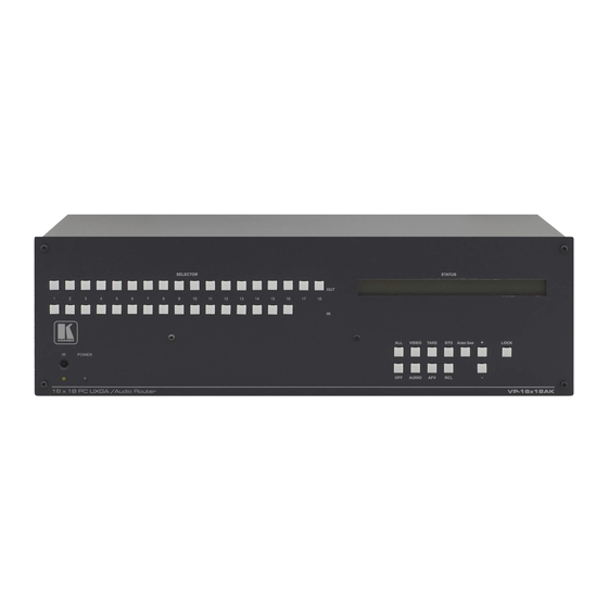
Defining the VP-16x18AK 16 x 18 PC UXGA/Audio Router Defining the VP-16x18AK 16 x 18 PC UXGA/Audio Router Figure 1 Table 1 define the front panel of the VP-16x18AK 16 x 18 PC UXGA/Audio Router. Figure 1: VP-16x18AK 16 x 18 PC UXGA/Audio Router Front Panel... -
Page 12: Table 1: Vp-16X18Ak 16 X 18 Pc Uxga/Audio Router Front Panel Features
1 For example, press ALL and then IN button 2 to connect input 2 to all the outputs Section 6 2 Also displays the number of input and output ports, the firmware version number and the machine number (see 3 When in the Confirm mode, the TAKE button lights KRAMER: SIMPLE CREATIVE TECHNOLOGY... -
Page 13: Figure 2: Vp-16X18Ak 16 X 18 Pc Uxga/Audio Router Rear Panel
Defining the VP-16x18AK 16 x 18 PC UXGA/Audio Router Figure 2 Table 2 define the rear panel of the VP-16x18AK 16 x 18 PC UXGA/Audio Router. Figure 2: VP-16x18AK 16 x 18 PC UXGA/Audio Router Rear Panel... -
Page 14: Table 2: Vp-16X18Ak 16 X 18 Pc Uxga/Audio Router Rear Panel Features
1 their factory default values (see Section PROG Button For the use of Kramer service personnel only RS-485 3-pin Terminal Block Connect to the corresponding pins A(+), B(–) and G on another device for RS-485 6 communication (see Section ... -
Page 15: Using The Ir Transmitter
This distance can be extended to up to 60m (200ft) when used with three extension cables Before using the external IR receiver, be sure to arrange for your Kramer dealer to insert the internal IR connection cable with the 3.5mm jack that... -
Page 16: Installing The Vp-16X18Ak In A Rack
Installing the VP-16x18AK in a Rack Installing the VP-16x18AK in a Rack This section describes what to do before installing in a rack and how to rack mount the VP-16x18AK. KRAMER: SIMPLE CREATIVE TECHNOLOGY... -
Page 17: Connecting And Configuring The Vp-16X18Ak
Connecting and Configuring the VP-16x18AK Connecting and Configuring the VP-16x18AK This section describes how to: Connect the VP-16x18AK (see 6 Section Connect a balanced stereo audio output (see 6 Section Connect the VP-16x18AK to a remote control device via: ... -
Page 18: Connecting The Audio Outputs To Balanced/Unbalanced Acceptors
Figure 3: Connecting the VP-16x18AK 16 x 18 PC UXGA/Audio Router 6.2 Connecting the Audio Outputs to Balanced/Unbalanced Acceptors Figure 4 illustrates how to connect the VP-16x18AK to a balanced acceptor. Figure 4: Connecting to a Balanced Acceptor KRAMER: SIMPLE CREATIVE TECHNOLOGY... -
Page 19: Connecting To The Vp-16X18Ak Via Rs-232
Connecting and Configuring the VP-16x18AK Figure 5 illustrates how to connect the VP-16x18AK to an unbalanced acceptor. Figure 5: Connecting to an Unbalanced Acceptor 6.3 Connecting to the VP-16x18AK via RS-232 You can connect to the VP-16x18AK via an RS-232 connection using, for example, a PC. -
Page 20: Connecting To The Vp-16X18Ak Via The Ethernet Port
Ethernet port on both units. 2. On the PC, click Start > Control Panel. 3. Double-click Network Connections. 4. Right-click, and from the menu select Properties. The Local Area Connection Properties window appears. 5. Select Internet Protocol (TCP/IP) (see Figure KRAMER: SIMPLE CREATIVE TECHNOLOGY... -
Page 21: Figure 6: Local Area Connection Properties Window
Connecting and Configuring the VP-16x18AK Figure 6: Local Area Connection Properties Window 6. Click the Properties button. 7. Select Use the following IP address, and fill in the details as shown in Figure 7. You can use any IP address in the range 192.168.1.1 to 192.168.1.255 (excluding 192.168.1.39) that is provided by your IT department. -
Page 22: Connecting Via A Network Hub, Switch, Or Router
DIP-switches 1, 2 and 3 determine the RS-485 machine number for the VP-16x18AK. When several VP-16x18AK units are connected, the machine number determines the unique identity of the VP-16x18AK in the sequence (see Table 1 Available from www.kramerav.com KRAMER: SIMPLE CREATIVE TECHNOLOGY... -
Page 23: Table 4: Machine Number Dip-Switch Settings
Connecting and Configuring the VP-16x18AK Note: When using a stand-alone VP-16x18AK unit set the machine number to 1 (factory default) When connecting more than one VP-16x18AK set the first machine (connected via RS-232) to be machine number 1. The other VP-16x18AK units must each be set to a unique machine number between 2 and 8. -
Page 24: Operating The Vp-16X18Ak Locally Via The Front Panel Buttons
To disconnect all outputs: Press the ALL button, followed by the OFF button 1 When the Audio button is lit the audio switching is selected 2 When the Video button is lit the video switching is selected KRAMER: SIMPLE CREATIVE TECHNOLOGY... -
Page 25: The At Once And Confirm Modes
Operating the VP-16x18AK Locally via the Front Panel Buttons 7.3 The At Once and Confirm Modes You can choose to work in the At Once or the Confirm mode. When the VP-16x18AK is set to the At Once mode, pressing an output-input combination implements the action immediately. -
Page 26: Setting The Audio Gain For Inputs And Outputs
After a few seconds the setting is saved. To set the treble level to 6 for output 14: 1. Press and hold the AUDIO GAIN button. The button lights red and the current output/bass setting is displayed. KRAMER: SIMPLE CREATIVE TECHNOLOGY... -
Page 27: Setting The Audio-Follow-Video Or Breakaway Option
Operating the VP-16x18AK Locally via the Front Panel Buttons 2. Press the AUDIO GAIN button a second time. The current treble setting is displayed. OUT: 08 TRE: 06 3. Press OUTPUT 14. Output 14 flashes on the Status display. 4. Press the + button to increase the treble gain or the – button to decrease the treble level. -
Page 28: Storing A Setup Configuration
Press and hold the Lock button until the button LED is no longer lit. The buttons are unlocked 1 Storing a new configuration over a previous configuration (without deleting it first) replaces the previous configuration KRAMER: SIMPLE CREATIVE TECHNOLOGY... -
Page 29: Operating The Vp-16X18Ak Remotely
Operating the VP-16x18AK Remotely Operating the VP-16x18AK Remotely The VP-16x18AK can be operated remotely via the following methods: The Kramer RC-IR3 Infra-Red Remote Control Transmitter RS-485 (see 6 Section RS-232 (see 8 Section Ethernet over a LAN (see ... -
Page 30: Figure 9: Control Configuration Via Rs-232
Operating the VP-16x18AK Remotely Figure 9: Control Configuration via RS-232 KRAMER: SIMPLE CREATIVE TECHNOLOGY... -
Page 31: Operating The Vp-16X18Ak Remotely Using A Web Browser
Operating the VP-16x18AK Remotely Using a Web Browser Operating the VP-16x18AK Remotely Using a Web Browser You can remotely operate the VP-16x18AK using a Web browser via the 9 Ethernet port (see Section .1). To be able to do so, you must use a supported Web browser;... -
Page 32: Figure 12: The Loading Page
Operating the VP-16x18AK Remotely Using a Web Browser Figure 12: The Loading Page The first time that you run the Kramer applet a security warning appears. Figure 13: First Time Security Warning 3. Click Run. The main switching control page is displayed which shows a graphical... -
Page 33: The Main Switching Matrix Page
Operating the VP-16x18AK Remotely Using a Web Browser There are three remote operation Web pages: Main switching matrix (see 9 Section Audio gain control (see 9 Section Configuration (see 9 Section Select a page by clicking on the relevant link on the left hand side of the window. -
Page 34: Switching An Input To An Output
Audio button for audio mode) channel that you want to switch. 9.2.2 Setting the AFV Mode Audio channel In 1 is currently switched to Out 4. To set the AFV mode: 1. Click the AFV button. The following warning appears. KRAMER: SIMPLE CREATIVE TECHNOLOGY... -
Page 35: Operating In The Offline Mode
Operating the VP-16x18AK Remotely Using a Web Browser Figure 17: AFV Mode Warning 2. Click OK. The AFV button outline becomes dark. All audio channels are switched according to the corresponding video channels. In this example, audio channel In 2 is now switched to Out 4. Figure 18: AFV Mode Audio Channels Switched All configuration changes now switch audio and video simultaneously. -
Page 36: Storing And Recalling Setups
1. From the Preset drop-down list, select a preset (in this example, Preset 07). Presets that currently contain configurations are displayed with a blue background; presets with no configuration have a white background. When you select a preset, the Store button changes from gray to dark blue. KRAMER: SIMPLE CREATIVE TECHNOLOGY... - Page 37 Operating the VP-16x18AK Remotely Using a Web Browser Figure 21: Selecting Preset 07 2. Click Store. A confirmation message appears. 3. Click OK. The configuration is stored in Preset 07. To recall a setup: 1. From the Preset drop-down list, select a preset (in this example, Preset 03).
-
Page 38: Locking The Front Panel Buttons
Note: Locking the front panel buttons does not disable remote operation of the unit via Ethernet, RS-232 or RS-485. 9.3 Audio Input Gain Control Page The Audio Gain page lets you set the gain for each of the input channels independently. Figure 24: Audio Gain Control Page KRAMER: SIMPLE CREATIVE TECHNOLOGY... -
Page 39: The Configuration Page
Operating the VP-16x18AK Remotely Using a Web Browser To change the audio gain (in this example, input gain for channel 2): 1. From the Input Gain drop-down list, click 02. Figure 25: Selecting Audio Input Gain for Channel 2 2. Click the – or + button to decrease or increase the gain. Hold the – or + button down to step quickly through the values. -
Page 40: Firmware Upgrade Using K-Upload
Web page using the new name or IP address. Firmware Upgrade Using K-Upload For instructions on upgrading the firmware, see the K-Upload Software Guide. The latest firmware and installation instructions can be downloaded from the Kramer Web site at http://www.kramerav.com. KRAMER: SIMPLE CREATIVE TECHNOLOGY... -
Page 41: Technical Specifications
Technical Specifications Technical Specifications Table 5 lists the technical specifications for the VP-16x18AK 16 x 18 PC UXGA/Audio Router. Table 5: Technical Specifications of the VP-16x18AK Note: All are measured on the local output unless specified otherwise INPUTS: 16 XGA on 15-pin HD connectors (VGA through UXGA) 16 unbalanced stereo audio on 3.5mm mini jacks OUTPUTS: 16 XGA on 15-pin HD connectors (VGA through UXGA) -
Page 42: Default Communication Parameters
Default Communication Parameters Default Communication Parameters Table 6 lists the default communication parameters as used in Kramer Electronics products. Table 6: Communication Parameters EDID EDID data is passed between Input 1 and Output 1 RS-232 Protocol 2000 Protocol 3000 (Default) - Page 43 Factory Default EDID Green chromaticity Gx 0.312 - Gy 0.559 Blue chromaticity Bx 0.148 - By 0.131 White point (default) Wx 0.320 - Wy 0.336 Additional descriptors None Timing characteristics Range limits Not available GTF standard Not supported Additional descriptors None Preferred timing Native/preferred timing...
-
Page 44: Table Of Ascii Codes For Serial Communication (Protocol 3000)
* Where X is the input number from 1 - 8. For example, for channel 7 and relative level -50dB, #AUD-LVL 1,7, -50CR Table 10 lists the codes that set the audio output gain. For more detailed 1 information, see Section 6.2. KRAMER: SIMPLE CREATIVE TECHNOLOGY... -
Page 45: Table Of Hex Codes For Serial Communication (Protocol 2000)
Table of Hex Codes for Serial Communication (Protocol 2000) Table 10: VP-16x18AK Audio Output Gain Codes Level … … OUTPUT 1 OUTPUT 5 OUTPUT Y* [Rel] … … #AUD-LVL 2,5, -100CR #AUD-LVL 2,Y, -100CR -100dB Mute #AUD-LVL 2,1, -100CR … …... -
Page 46: Table 14: Vp-16X18Ak Hex Codes For Setting The Audio Input Gain
81 … 16 85 F8 81 … 16 8Y F8 16 81 F8 81 … 16 85 FF 81 … 81 +10dB (Max) 16 8Y FF 16 81 FF *BYTE 3 = 0x80 + Gain Value (0x00-0x7F) KRAMER: SIMPLE CREATIVE TECHNOLOGY... -
Page 47: Kramer Protocol
Kramer Protocol Kramer Protocol 1 By default, the VP-16x18AK is set to protocol 3000 (see Section 6.2) but is also compatible with Kramer’s Protocol 2000 1 (see Section 6.3). 1 6.1 Section describes how to switch between protocol 3000 and protocol 2000. -
Page 48: Protocol 3000 Syntax
Host messages - Carriage Return (ASCII 13), will be referred to by CR in this document. Machine messages - Carriage Return (ASCII 13) + Line-Feed (ASCII 10), will be referred to by CRLF. Spaces between parameters or command parts will be ignored. KRAMER: SIMPLE CREATIVE TECHNOLOGY... -
Page 49: Table 17: Instruction Codes For Protocol 3000
Response Protocol Handshaking ~OKCRLF Device initiated messages Command Syntax Start message Kramer Electronics LTD. , Device Model Version Software Version Switcher actions Audio-video channel has switched (AFV mode) AV IN>OUT Video channel has switched (Breakaway mode) VID IN>OUT Audio channel has switched (Breakaway mode) AUD IN>OUT... - Page 50 Then disconnect audio output 1. ~AUD 0>1 OKCRLF Then get status of all links (assume this is 4x4 matrix). ~V 1>1, 0>2, 1>3, Commands processing start after entering CR, response will sent 3>4 CRLF for each command after processing it. KRAMER: SIMPLE CREATIVE TECHNOLOGY...
- Page 51 Kramer Protocol Signal Status commands Command Syntax Response Change signal status SIGNAL INPUT, STATUS ------------------- Get signal status SIGNAL? INPUT SIGNAL INPUT, STATUS Parameters Description: INPUT = Input number, ‘*’ for all. STATUS = Signal state: "0" or "off" for not existent signal.
- Page 52 Numeric value (present audio processing stage). For example: "0" for Input level, "1" for Pre-Amplifier, "2" for Amplifier (Out) etc. OUTPUT = Output # CHANNEL = Input or Output # VOLUME = Audio parameter in Kramer units, precede minus sign for negative values. increase current value, decrease current value MUTE MODE = 1 – Mute 0 –...
- Page 53 Kramer Protocol Machine info commands Command Syntax Response * Time settings commands require admin authorization Read in\outs count INFO-IO? INFO-IO: IN INPUTS_COUNT, OUT OUTPUTS_COUNT INFO-PRST? Read max presets INFO-PRST: VID PRESET_VIDEO_COUNT, AUD count PRESET_AUDIO_COUNT FACTORY Reset FACTORY RESULT configuration to...
- Page 54 AFV AFV-MODE video mode AFV-MODE = Front panel AFV mode "0" or "afv" to set front panel switching buttons in audio-follow-video state. "1" or "brk" to set front panel switching buttons in their previous state when audio. KRAMER: SIMPLE CREATIVE TECHNOLOGY...
-
Page 55: Kramer Protocol 2000
Kramer Protocol 16.3 Kramer Protocol 2000 This RS-232/RS-485 communication protocol uses four bytes of information as defined below. The default data rate is 115200 baud, with no parity, 8 data bits and 1 stop bit. Table 18: Protocol Definitions DESTI-... -
Page 56: Table 19: Instruction Codes For Protocol 2000
1 - Panel locked REQUEST WHETHER PANEL IS LOCKED 0 – Gain AUDIO PARAMETER INPUT Bit: SETTINGS FOR I0 - 0=input; 1=output INSTRUCTIONS 22, 24, 25 I1 - Left I2 - Right CHANGE TO ASCII Kramer protocol 3000 KRAMER: SIMPLE CREATIVE TECHNOLOGY... - Page 57 Kramer Protocol INSTRUCTION DEFINITION FOR SPECIFIC INSTRUCTION NOTE DESCRIPTION INPUT OUTPUT IDENTIFY MACHINE 1 - video machine name 0 - Request first 4 digits 2 - audio machine name 1 - Request first suffix 3 - video software version 2 - Request second suffix...
- Page 58 (in real-time). For example, if input 3 is detected as invalid, the unit will send the HEX codes If input 7 is detected as valid, then the unit will send HEX codes KRAMER: SIMPLE CREATIVE TECHNOLOGY...
- Page 60 For the latest information on our products and a list of Kramer distributors, visit our Web site: www.kramerAV.com, where updates to this user manual may be found. We welcome your questions, comments and feedback. Safety Warning: Disconnect the unit from the power supply before opening/servicing.
Need help?
Do you have a question about the VP-16X18AK/110V and is the answer not in the manual?
Questions and answers