Table of Contents
Advertisement
Quick Links
Download this manual
See also:
User Manual
Advertisement
Table of Contents

Related Manuals for Kramer VP-16x18AK


Summary of Contents for Kramer VP-16x18AK
- Page 1 Kramer Electronics, Ltd. USER MANUAL Model: VP-16x18AK 16 x 18 PC UXGA/Audio Router...
-
Page 2: Table Of Contents
Quick Start Overview Recommendations for Best Performance Shielded Twisted Pair and Unshielded Twisted Pair Defining the VP-16x18AK 16 x 18 PC UXGA/Audio Router Using the IR Transmitter Installing the VP-16x18AK in a Rack Connecting and Configuring the VP-16x18AK Connecting the VP-16x18AK... - Page 3 16.3 Kramer Protocol 2000 Figures Figure 1: VP-16x18AK 16 x 18 PC UXGA/Audio Router Front Panel Figure 2: VP-16x18AK 16 x 18 PC UXGA/Audio Router Rear Panel Figure 3: Connecting the VP-16x18AK 16 x 18 PC UXGA/Audio Router Figure 4: Connecting to a Balanced Acceptor...
- Page 4 Figure 25: Selecting Audio Input Gain for Channel 2 Figure 26: Configuration Page Tables Table 1: VP-16x18AK 16 x 18 PC UXGA/Audio Router Front Panel Features Table 2: VP-16x18AK 16 x 18 PC UXGA/Audio Router Rear Panel Features Table 3: DIP-switch Settings...
-
Page 5: Introduction
Introduction Introduction Welcome to Kramer Electronics! Since 1981, Kramer Electronics has been providing a world of unique, creative, and affordable solutions to the vast range of problems that confront video, audio, presentation, and broadcasting professionals on a daily basis. In recent years, we have redesigned and... -
Page 6: Quick Start
European Advanced Recycling Network (EARN) and will cover any costs of treatment, recycling and recovery of waste Kramer Electronics branded equipment on arrival at the EARN facility. For details of Kramer’s recycling arrangements in your particular country go to our recycling pages at http://www.kramerelectronics.com/support/recycling/. - Page 7 Getting Started...
-
Page 8: Overview
VP-16x18AK is HDTV compatible and lets you simultaneously route any or all of the 16 inputs to any or all of the 18 outputs. In particular, the VP-16x18AK, 16 x 18 PC UXGA/Audio Router features: • Kramer’s innovative integrated sync processing; Kr-isp ®... -
Page 9: Recommendations For Best Performance
Overview You can operate the VP-16x18AK using the front panel buttons, or remotely via: • RS-485, RS-232 serial or Ethernet TCP/UDP commands (using Kramer 2000 and 3000 protocols) transmitted by a touch screen system, PC or other serial/Ethernet controller • The Kramer Infrared Remote Control transmitter or Infrared remote extension cable transmitter (optional) •... -
Page 10: Defining The Vp-16X18Ak 16 X 18 Pc Uxga/Audio Router
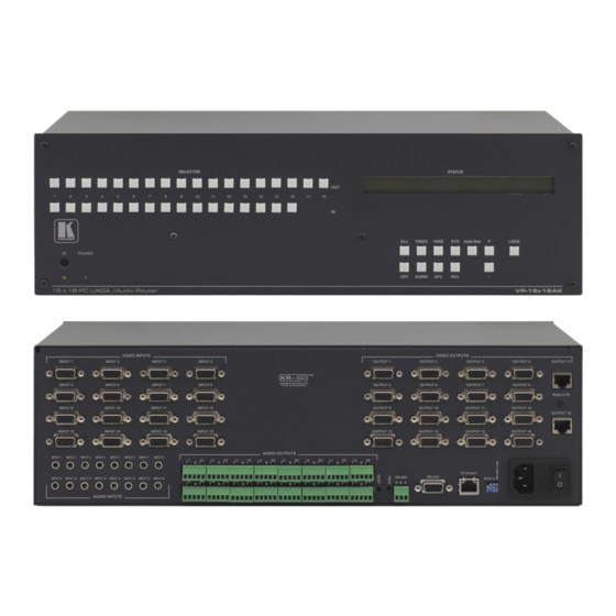
Figure 1 Table 1 define the front panel of the VP-16x18AK 16 x 18 PC UXGA/Audio Router. Figure 1: VP-16x18AK 16 x 18 PC UXGA/Audio Router Front Panel Table 1: VP-16x18AK 16 x 18 PC UXGA/Audio Router Front Panel Features... - Page 11 Defining the VP-16x18AK 16 x 18 PC UXGA/Audio Router Feature Function OFF Button Press a SELECTOR OUT button followed by OFF to disconnect the selected output from he input (see Section 7.2). Press ALL followed by OFF to disconnect all outputs...
-
Page 12: Figure 2: Vp-16X18Ak 16 X 18 Pc Uxga/Audio Router Rear Panel
Defining the VP-16x18AK 16 x 18 PC UXGA/Audio Router Figure 2 Table 2 define the rear panel of the VP-16x18AK 16 x 18 PC UXGA/Audio Router. Figure 2: VP-16x18AK 16 x 18 PC UXGA/Audio Router Rear Panel KRAMER: SIMPLE CREATIVE TECHNOLOGY... -
Page 13: Table 2: Vp-16X18Ak 16 X 18 Pc Uxga/Audio Router Rear Panel Features
Defining the VP-16x18AK 16 x 18 PC UXGA/Audio Router Table 2: VP-16x18AK 16 x 18 PC UXGA/Audio Router Rear Panel Features Feature Function VIDEO INPUTS 15-pin HD (F) Connectors Connect to he VGA sources (from 1 to 16) AUDIO OUTPUTS Removable Terminal Block... -
Page 14: Using The Ir Transmitter
This distance can be extended to up to 60m (200ft) when used with three extension cables Before using the external IR receiver, be sure to arrange for your Kramer dealer to insert the internal IR connection cable with the 3.5mm jack that... -
Page 15: Installing The Vp-16X18Ak In A Rack
Installing the VP-16x18AK in a Rack Installing the VP-16x18AK in a Rack This section describes what to do before installing in a rack and how to rack mount the VP-16x18AK. -
Page 16: Connecting And Configuring The Vp-16X18Ak
1 You do not need to connect all inputs and outputs 2 Switch off the power on each device before connecting it to your VP-16x18AK After connecting your VP-16x18AK, switch on its power and then switch on the power on each device Do NOT push in the rear panel PROG button, it is reserved... -
Page 17: Connecting The Audio Outputs To Balanced/Unbalanced Acceptors
Connecting and Configuring the VP-16x18AK Figure 3: Connecting the VP-16x18AK 16 x 18 PC UXGA/Audio Router Connecting the Audio Outputs to Balanced/Unbalanced Acceptors Figure 4 illustrates how to connect the VP-16x18AK to a balanced acceptor. Figure 4: Connecting to a Balanced Acceptor... -
Page 18: Connecting To The Vp-16X18Ak Via Rs-232
5 to pin 5 need be connected) to the RS-232 9-pin D-sub port on your PC Connecting to the VP-16x18AK via RS-485 You can operate the VP-16x18AK via the RS-485 port from a distance of up to 1200m (3900ft) using a PC equipped with a card that provides an RS-485 port To connect a PC or controller to the RS-485 port on the VP-16x18AK: 1. -
Page 19: Connecting To The Vp-16X18Ak Via The Ethernet Port
IT department regarding a suitable IP address. 6.5.1 Connecting Directly to the Ethernet Port You can connect the Ethernet port of the VP-16x18AK to the Ethernet port on your PC via a crossover cable with RJ-45 connectors. This type of connection is recommended for identification of the factory... -
Page 20: Figure 6: Local Area Connection Properties Window
Connecting and Configuring the VP-16x18AK Figure 6: Local Area Connection Properties Window 6. Click the Properties button. 7. Select Use the following IP address, and fill in the details as shown in Figure 7. You can use any IP address in the range 192.168.1.1 to 192.168.1.255 (excluding 192.168.1.39) that is provided by your IT... -
Page 21: Connecting Via A Network Hub, Switch, Or Router
Connecting and Configuring the VP-16x18AK 6.5.2 Connecting via a Network Hub, Switch, or Router You can connect the Ethernet port of the VP-16x18AK to the Ethernet port on a network hub, switch, or router, via a straight-through cable with RJ-45 connectors. -
Page 22: Table 4: Machine Number Dip-Switch Settings
Connecting and Configuring the VP-16x18AK Note: • When using a stand-alone VP-16x18AK unit set the machine number to 1 (factory default) • When connecting more than one VP-16x18AK set the first machine (connected via RS-232) to be machine number 1. The other VP-16x18AK units must each be set to a unique machine number between 2 and 8. -
Page 23: Operating The Vp-16X18Ak Locally Via The Front Panel Buttons
Operating the VP-16x18AK Locally via the Front Panel Buttons Operating the VP-16x18AK Locally via the Front Panel Buttons The Status Display For a few seconds after being powered on, the unit’s model, machine number and firmware version are displayed on the Status display. -
Page 24: The At Once And Confirm Modes
7.3 The At Once and Confirm Modes You can choose to work in the At Once or the Confirm mode. When the VP-16x18AK is set to the At Once mode, pressing an output-input combination implements the action immediately. In the Confirm mode (the TAKE button is lit), the TAKE button must be pressed to execute the switch. -
Page 25: Setting The Audio Gain For Inputs And Outputs
Operating the VP-16x18AK Locally via the Front Panel Buttons To confirm several actions (in the Confirm mode): 1. Press each OUTPUT-INPUT combination in sequence. The corresponding input numbers that are displayed in the LCD readout flash. The TAKE button also flashes. -
Page 26: Setting The Audio-Follow-Video Or Breakaway Option
Operating the VP-16x18AK Locally via the Front Panel Buttons 2. Press the AUDIO GAIN button a second time. The current treble setting is displayed. OUT: 08 TRE: 06 3. Press OUTPUT 14. Output 14 flashes on the Status display. 4. Press the + button to increase the treble gain or the – button to decrease the treble level. -
Page 27: Storing A Setup Configuration
• Press and hold the Lock button until the button LED is no longer lit. The buttons are unlocked Reading and Writing the EDID The VP-16x18AK is delivered with default EDID data programmed in each input. This can be modified by using the EDID Designer software to read and write EDID data via RS-232 or Ethernet. -
Page 28: Operating The Vp-16X18Ak Remotely
1. Connect the video sources and acceptors, the appropriate audio sources and acceptors, and the power cord to each VP-16x18AK. 2. Connect the RS-232 port on the first VP-16x18AK to the PC (see Section 3. Set the machine number to 1 of the unit connected to the PC. -
Page 29: Figure 9: Control Configuration Via Rs-232
Operating the VP-16x18AK Remotely Figure 9: Control Configuration via RS-232... -
Page 30: Operating The Vp-16X18Ak Remotely Using A Web Browser
• Load and enable Java • Enable Javascript in your browser Connecting to the VP-16x18AK via your Browser Make sure that your PC is connected via a network to the VP-16x18AK and do the following: 1. Open your Internet browser. -
Page 31: Figure 12: The Loading Page
Operating the VP-16x18AK Remotely Using a Web Browser Figure 12: The Loading Page The first time that you run the Kramer applet a security warning appears. Figure 13: First Time Security Warning 3. Click Run. The main switching control page is displayed which shows a graphical... -
Page 32: The Main Switching Matrix Page
Operating the VP-16x18AK Remotely Using a Web Browser There are three remote operation Web pages: • Main switching matrix (see Section • Audio gain control (see Section • Configuration (see Section Select a page by clicking on the relevant link on the left hand side of the window. -
Page 33: Switching An Input To An Output
Operating the VP-16x18AK Remotely Using a Web Browser 9.2.1 Switching an Input to an Output To switch an input to an output, for example, video input 1 to video output 4: 1. Click the blue Video button. The button outline becomes dark. Actions now relate to video channels. -
Page 34: Operating In The Offline Mode
Operating the VP-16x18AK Remotely Using a Web Browser Figure 17: AFV Mode Warning 2. Click OK. The AFV button outline becomes dark. All audio channels are switched according to the corresponding video channels. In this example, audio channel In 2 is now switched to Out 4. -
Page 35: Storing And Recalling Setups
Operating the VP-16x18AK Remotely Using a Web Browser Figure 19: Switching Audio in the Offline Mode 3. If required, repeat Step 2 for several audio/video channels. 4. Click either Take to accept the change or Cancel to discard the changes. - Page 36 Operating the VP-16x18AK Remotely Using a Web Browser Figure 21: Selecting Preset 07 2. Click Store. A confirmation message appears. 3. Click OK. The configuration is stored in Preset 07. To recall a setup: 1. From the Preset drop-down list, select a preset (in this example, Preset 03).
-
Page 37: Locking The Front Panel Buttons
Operating the VP-16x18AK Remotely Using a Web Browser 2. Click Recall. A confirmation message appears. 3. Click OK. The configuration from Preset 03 is loaded. Note: You can also recall a preset in the Offline mode (see Figure 24) and... -
Page 38: The Configuration Page
Operating the VP-16x18AK Remotely Using a Web Browser To change the audio gain (in this example, input gain for channel 2): 1. From the Input Gain drop-down list, click 02. Figure 25: Selecting Audio Input Gain for Channel 2 2. Click the – or + button to decrease or increase the gain. Hold the – or + button down to step quickly through the values. -
Page 39: Firmware Upgrade Using K-Upload
Web page using the new name or IP address. Firmware Upgrade Using K-Upload For instructions on upgrading the firmware, see the K-Upload Software Guide. The latest firmware and installation instructions can be downloaded from the Kramer Web site at www.kramerelectronics.com. -
Page 40: Technical Specifications
Technical Specifications Technical Specifications Table 5 lists the technical specifications for the VP-16x18AK 16 x 18 PC UXGA/Audio Router. Table 5: Technical Specifications of the VP-16x18AK Note: All are measured on the local output unless specified otherwise INPUTS: 16 XGA on 15-pin HD connectors (VGA hrough UXGA) -
Page 41: Default Communication Parameters
Default Communication Parameters Default Communication Parameters Table 6 lists the default communication parameters as used in Kramer Electronics products. Table 6: Communication Parameters EDID EDID data is passed between Input 1 and Output 1 RS-232 Protocol 2000 Protocol 3000 (Default) - Page 42 1400 x 1050p at 60Hz 1440 x 900p at 60Hz 1600 x 1200p at 60Hz Report information Date generated 11/15/2010 Software revision 2.43.0.822 Operating system 5.1 2600 2.Service Pack 3 Raw data 00,FF,FF,FF,FF,FF,FF,00,2E,4D,08,08,02,00,00,00,0A,13,01,03,6E,24,1D,64,EE,9C,20,9C,54,4F,8F,26, 21,52,56,3F,CF,00,81,80,81,40,90,40,95,00,A9,40,D1,00,D1,C0,01,01,64,19,00,40,41,00,26,30,18,88, 36,00,30,E4,10,00,00,18,BC,1B,00,A0,50,20,17,30,30,20,36,00,20,20,00,00,00,1A,00,00,00,FC,00,56, 50,2D,38,58,38,54,50,0A,20,20,20,20,00,00,00,10,00,56,50,2D,38,58,38,54,50,20,0A,20,20,20,00,4A KRAMER: SIMPLE CREATIVE TECHNOLOGY...
-
Page 43: Table Of Ascii Codes For Serial Communication (Protocol 3000)
(Protocol 3000) Table 7 Table 8 list the ASCII values to switch an input to an output for a single VP-16x18AK machine. For more detailed information, see Protocol 3000 (Section 16.2). Table 7: VP-16x18AK Video Signal Codes for Protocol 3000 OUT 1 …... -
Page 44: Table Of Hex Codes For Serial Communication (Protocol 2000)
The Hex codes listed in this section are used to set video channels for a single machine (set as machine number 1) connected via either RS-232 or Ethernet. Similar hex codes are used when the VP-16x18AK is connected via RS-485 and the VP-16x18AK is set to machine number 2. -
Page 45: Table 14: Vp-16X18Ak Hex Codes For Setting The Audio Input Gain
Table of Hex Codes for Serial Communication (Protocol 2000) Table 14 lists the Hex values that set the audio input gain: Table 14: VP-16x18AK Hex Codes for Setting the Audio Input Gain Level IN 1 … IN 5 … IN X... -
Page 46: Kramer Protocol
® The Windows -based Kramer control software operates with protocol 2000. If the VP-16x18AK is set to protocol 3000, it is automatically switched to protocol 2000. 16.2 Kramer Protocol 3000 This RS-232/RS-485 communication protocol lets you control the machine from any standard terminal software (for example, Windows®... -
Page 47: Protocol 3000 Syntax
Kramer Protocol 16.2.1 Protocol 3000 Syntax Host message format: Start Address (optional) Body Delimiter device_id@ message Simple command (commands string with only one command without addressing): start body delimiter Command SP Parameter_1,Parameter_2,… Commands string (formal syntax with commands concatenation and addressing): # Address@ Command_1 Parameter1_1,Parameter1_2,…... -
Page 48: Table 17: Instruction Codes For Protocol 3000
Response Protocol Handshaking ~OKCRLF Device initiated messages Command Syntax Start message Kramer Electronics LTD. , Device Model Version Software Version Switcher actions Audio-video channel has switched (AFV mode) AV IN>OUT Video channel has switched (Breakaway mode) VID IN>OUT Audio channel has switched (Breakaway mode) AUD IN>OUT... - Page 49 Kramer Protocol Basic routing commands Command Syntax Response Switch audio & video AV IN>OUT, IN>OUT, … AV IN>OUT, IN>OUT,…RESULT Switch video only VID IN>OUT, IN>OUT, … VID IN>OUT, IN>OUT, …RESULT Short form: V IN>OUT, IN>OUT, … Note: When AFV mode is active, his command will switch also audio. If audio is breakaway – device display mode will change to show audio connec ions status.
- Page 50 #PRST-STR 5CR ~PRST-STR 5 OKCRLF connections to preset 5 Recall Audio & Video #PRCL 3CR ~PRST-RCL 3 OKCRLF connections from preset 3 Show source of video output 2 #PRST-VID? 3,2CR ~PRST-VID 3: 4>2 CRLF from preset 3 KRAMER: SIMPLE CREATIVE TECHNOLOGY...
- Page 51 Numeric value (present audio processing stage). For example: "0" for Input level, "1" for Pre-Amplifier, "2" for Amplifier (Out) etc. CHANNEL = Input or Output # VOLUME = Audio parameter in Kramer units, precede minus sign for negative values. increase current value, decrease current value MUTE MODE = 1 –...
- Page 52 * Response will send after machine number has been changed. So the replay with header will be: NEW_MACHINE_NUMBER @MACH-NUM OLD_MACHINE_NUMBER NEW_MACHINE_NUMBER OK Network settings commands Set IP Address NET-IP IP_ADDRESS NET-IP IP_ADDRESS RESULT NTIP NET-IP? Read IP Address NET-IP IP_ADDRESS NTIP? NET-MAC? Read MAC Address NET-MAC MAC_ADDRESS NTMC KRAMER: SIMPLE CREATIVE TECHNOLOGY...
- Page 53 Kramer Protocol Network settings commands Set subnet mask NET-MASK SUBNET_MASK NET-MASK SUBNET_MASK RESULT NTMSK NET-MASK? Read subnet mask NET-MASK SUBNET_MASK NTMSK? Set gateway address NET-GATE GATEWAY_ADDRESS NET-GATE GATEWAY_ADDRESS RESULT NTGT NET-GATE? Read subnet mask NET-GATE GATEWAY_ADDRESS NTGT? Set DHCP mode...
-
Page 54: Kramer Protocol 2000
For a single machine controlled via the serial port, always set M4 M0 = 1, and make sure that the machine itself is configured as MACHINE NUMBER = 1 Table 19: Instruction Codes for Protocol 2000 Note: All values in the table are decimal, unless otherwise stated KRAMER: SIMPLE CREATIVE TECHNOLOGY... - Page 55 2 - Treble I2 - Right 3 - Midrange 4 - Mix On CHANGE TO ASCII Kramer protocol 3000 IDENTIFY MACHINE 1 - video machine name 0 - Request first 4 digits 2 - audio machine name 1 - Request first suffix...
- Page 56 If the OUTPUT is set as 1, then the ASCII coding of the lettering following the machine’s name is sent For example, for the VS-7588YC, the reply to the request to send the first suffix would be (HEX codes): 81 (i e 128dec+ ASCII for “Y”; 128dec+ ASCII for “C”) KRAMER: SIMPLE CREATIVE TECHNOLOGY...
- Page 57 Kramer Protocol NOTE 14 - The number of inputs and outputs refers to the specific machine which is being addressed, not to the system For example, if six 16X16 matrices are configured to make a 48X32 system (48 inputs, 32 outputs), the reply to the HEX code...
- Page 59 For the latest information on our products and a list of Kramer distributors visit www.kramerelectronics.com where updates to this user manual may be found. We welcome your questions, comments and feedback. Safety Warning: Disconnect the unit from the power supply before opening/servicing.
Need help?
Do you have a question about the VP-16x18AK and is the answer not in the manual?
Questions and answers